Cattron North America MRF220 220MHz VHF TRANSCEIVER User Manual REVISED EXTRACT FROM ACCUSPEED 220
Laird Controls North America Inc. 220MHz VHF TRANSCEIVER REVISED EXTRACT FROM ACCUSPEED 220
UserManual.wiki
>
Cattron North America
>
MRF220 User Manual
USERS MANUAL
Navigation menu
Upload a User Manual
Namespaces
Wiki Guide
HTML
PDF
Info
Views
User Manual
Discussion / Help
Navigation
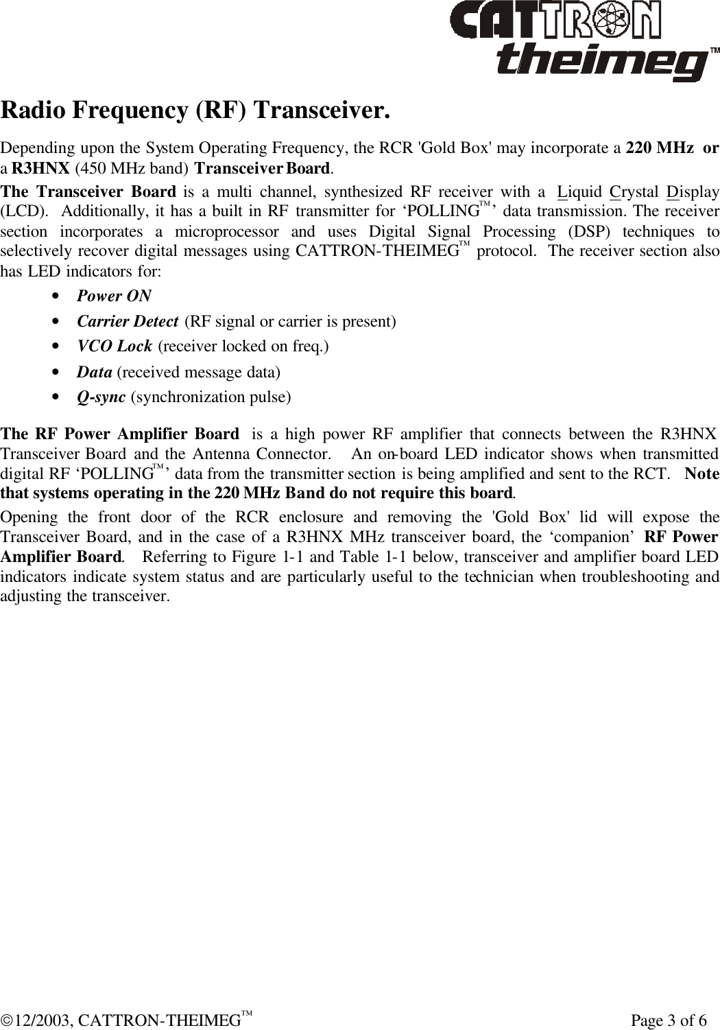
![Page 4 of 6 12/2003, CATTRON-THEIMEG™ MP 96 GII LCU [RCR] – Functional Description. Radio Frequency (RF) Transceiver, continued. Figure 1-1. Transceiver & RF Amplifier Board LED Indicators R3HNX (450 Mz) TRANSCEIVERBOARDHRF AMPLIFIER BOARD220 Mz TRANSCEIVER BOARDHVCOLOCKLED DATALEDQ-SYNCLEDCARRIERDETECTLEDRECEIVERPOWERLEDVCOLOCKLEDDATALEDRF POWERLEDTO ANTTO RXTO TXQ-SYNCLEDCARRIERDETECTLEDRECEIVERPOWERLED Table 1-1. Transceiver & RF Amplifier Board LED Indicators LED Description Transceiver Power This red LED indicates the presence of DC power on the transceiver circuit board. Carrier Detect The green Carrier Detect LED indicates that the receiver section is receiving a RF signal. Data This yellow LED indicates that the received RF message contains data. Q-Sync This orange LED indicates an interrupt that signifies the computer/ decoder has received a new message. VCO Lock This red LED (located underneath the EMI/RFI shield on the R3HNX board) illuminates when the transceiver frequency synthesizer is unable to lock onto the required frequency. RF Power LED This red LED (located on the RF amplifier) flashes when the transmitted digital RF ‘POLLING™’ data from the transmitter is being amplified and sent to the RCT](https://usermanual.wiki/Cattron-North-America/MRF220/User-Guide-379960-Page-4.png)
![12/2003, CATTRON-THEIMEG™ Page 5 of 6 SYSTEM SUMMARY – Technical Specifications LCU [RCR] Enclosure: 20"L x 20"H x 8"W (50.80cm x 50.80cm x 20.32cm), NEMA 4 (IP66) Steel. Weight: Approximately 70 lbs (31.75 kg) Environment: Outdoors, -22°F to 150°F (-30°C to 65°C), RH 0 to 95% non-condensing (-40°F units available – contact factory for details) Electrical Input/Output connections: Qty 4, quick connect/disconnect plugs and sockets Solid State Digital Outputs: Total of 96 rated at 100VDC with individual fusing at 5A Solid State Digital Inputs: Total of 48 rated at 74VDC with individual fusing at 5A Electro-mechanical Outputs: 100VDC @ 10A Output Termination: 2 screw terminals per I/O position Receiver/Decoder Power Source: DC-DC converter; 24-78 VDC Input/13.8 VDC output @ 0.8 A with Under/Over Voltage protection Minimum Locomotive Battery voltage: 62VDC Micro-controllers Qty 3, Intel™ 8051 family microprocessors Serial Communication Ports: RS232 port for GPS Receiver/clock and external event recorder RS485 port for locomotive monitoring Frequency Range: VHF 220-222 MHz (FCC), 217-219 MHz (Industry Canada) or UHF 447-473 MHz Channel Spacing: UHF 12.5 kHz, VHF 12.5 kHz & 15 kHz Emission/Modulation: UHF 9K80F1D ±2.5 kHz deviation, VHF 8K50F1D ±1.85kHz deviation (12.5kHz channel spacing), VHF 10K1F1D ±2.66kHz deviation (15kHz channel spacing) RF Transmit Power: UHF 1.6W, VHF 2.5W (both options factory set) Range: 1-mile line of site Duty Cycle: 2.5875% Antennas: Qty 1, mounted vertically for receive and transmit. Gain: UHF 5dB, VHF 3dB Approvals: US FCC (Part 90) Industry Canada (RSS119) Receiver Sensitivity: 0.5 µV (20 dB quieting) typical Frequency Stability: ±0.0002% of reference frequency Decoder Microprocessor Speed: 11.059 MHz Axle Generator: 120 PPR Dual Phase. NOTE: As part of our ‘continuous improvement’ policy, CATTRON-THEIMEG™ reserves the right to change specifications without notice.](https://usermanual.wiki/Cattron-North-America/MRF220/User-Guide-379960-Page-5.png)
![Page 6 of 6 12/2003, CATTRON-THEIMEG™ SYSTEM SUMMARY – Technical Specifications, continued OCU [RCT] Case Material: Cast Magnesium with high strength powder-coat finish Environment: Outdoors, -40°F to 140°F (-40°C to 60°C), RH 0 to 95% non-condensing Watertight NEMA 3S (IP65) (Heavy Rain, Dust, Oil Resistant) Weight: Less than 3.5 lbs (1.6 kg) including battery Size: Approx. 10"L x 3.5"W x 4.5"H (25.40 cm x 8.89 cm x 11.43 cm) Battery: Industry Standard 7.2VDC Rechargeable Nickel Metal Hydride (Ni-MH) Battery Pack mounted externally to bottom of OCU Battery Life: Ni-MH – approximately 12 hours continuous operation Antenna: Externally Mounted ‘stubby’ whip antenna for optimum signal transmission Frequency Range: VHF 220-222 MHz (FCC), 217-219 MHz (Industry Canada) or UHF 447-473 MHz Channel Spacing: UHF 12.5 kHz, VHF 12.5 kHz & 15 kHz Emission/Modulation: UHF 9K00F1D ±2.5 kHz deviation, VHF 8K50F1D ±1.85kHz deviation (12.5kHz channel spacing), VHF 10K1F1D ±2.66kHz deviation (15kHz channel spacing) RF Transmit Power: UHF 500 mW, VHF 500mW or 2.5W (factory set) Range: 1-mile line of sight Duty Cycle: 2.5875% Approvals: US FCC (Part 90) Industry Canada (RSS119) Carrying Device: Tear away harness meeting FRA Safety Advisory 2001-01 NOTE: As part of our ‘continuous improvement’ policy, CATTRON-THEIMEG™ reserves the right to change specifications without notice.](https://usermanual.wiki/Cattron-North-America/MRF220/User-Guide-379960-Page-6.png)