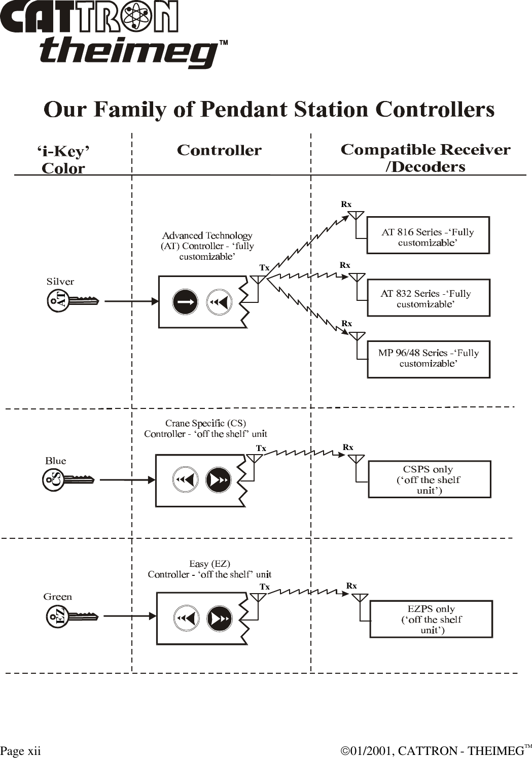
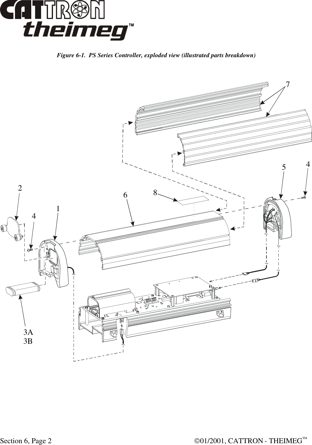
Cattron North America PS Industrial R/C Transmitter User Manual PS Controller Manaul

Laird Controls North America Inc. Industrial R/C Transmitter PS Controller Manaul

users manual

         PENDANT STATION CONTROLLER  OPERATION & MAINTENANCE MANUAL          CUSTOMER:    MODEL NUMBER:  SERIAL NUMBER:  FREQUENCY ASSIGNMENT:  ADDRESS ASSIGNMENT:  MANUAL P/N:                            68C-PS REV 000 01/2001
 01/2001, CATTRON - THEIMEGTM  Page i  PENDANT STATION CONTROLLER   OPERATION & MAINTENANCE INSTRUCTIONS   IMPORTANT NOTICES   The security ‘i-Key’ that accompanies your Pendant Station (PS) controller has been pre-programmed with certain system operating parameters before leaving our factory.  If your PS controller is of the Advanced Technology (AT) family that is custom built to your specification, such ‘i-Key’ parameters will include a specific address and operating frequency.  However, CATTRON-THEIMEG™ strongly advises you to check that our pre-configured address and frequency is not duplicated in other remote control equipment located at, or around, your operating facility.  When returning an PSAT Pendant controller to CATTRON-THEIMEG™ for repair, the original coded ‘i-Key’ supplied with the unit shall be returned with the unit.  When returning a PSEZ or PSCS Pendant controller to CATTRON-THEIMEG™ for repair, we recommend the coded ‘i-Key’ last used with the unit be returned with the unit.  Before returning a PSEZ or PSCS Pendant controller to CATTRON-THEIMEG™ for repair, we strongly recommend you record the operating address and frequency assigned to the controller as you will be required to re-program these operating parameters after we return your controller.  Refer to Frequency and Address Reports in Section 5 of this manual for recording details.  When a PSEZ or PSCS Pendant controller is returned to CATTRON-THEIMEG™ for repair, we make every effort to establish the operating address and frequency assigned to your controller when it arrives at our repair facility.  Whenever such operands can be established, we will record the same on the service documentation returned with your controller.  This equipment is firmware based. Any duplication of operating firmware without written consent of CATTRON-THEIMEG™ is prohibited.  U.S. Copyright Laws protect all firmware, parts and product listings, assembly files, and this manual.
 Page ii  01/2001, CATTRON - THEIMEGTM List of Technical Abbreviations The following abbreviations (acronyms) are frequently used in CATTRON-THEIMEG™ Radio Remote Control Technology and may be used in this manual:  AC Alternating Current LED Light Emitting Diode AT Advanced Technology ML Mainline ASO Automatic Safety Override NEMA National Electrical Manufacturer’s Association BCH Bose-Chaudhuri-Hocquenghem (data error detection routines) Ni-Cad Nickel Cadmium CMOS Complimentary Metal Oxide Semiconductor OPR Operate CS Crane Specific PRC Portable Remote Control DC Direct Current PS Pendant Station DOC Department of Communication (Canada) PTO Push-to-Operate  DP Dual Pressure RF Radio Frequency EDP Electronic Data Processing RFI Radio Frequency Interference EEPROM Electrically Erasable Programmable Read Only Memory RST Reset Relay EMI Electro-Magnetic Interference SP Single Pressure EPROM Erasable Programmable Read Only Memory SYNC Synchronization FCC Federal Communications Commission TP Test Point GND Ground TS Transfer Switch I/O Input/Output VAC Volts Alternating Current  IR  Infra-red VDC Volts Direct Current  LCD Liquid Crystal Display VFD Variable Frequency Drive
 01/2001, CATTRON - THEIMEGTM  Page iii Introduction How to use this Manual. This manual contains generic operation and maintenance procedures applicable to the entire series of CATTRON-THEIMEG™ Pendant Station (PS) Radio Remote Controllers. If you are using our Advanced Technology (AT) family of controllers that have been customized and pre-programmed to your exact specification, you should skip Section 5 in its entirety as the frequency and address programming procedures contained therein do not apply to your controller.  If you are using our PSEZ or PSCS family of controllers, you should include Section 5, as you will be required to verify/program the system address and operating frequency before using your controller for the first time.
 Page iv  01/2001, CATTRON - THEIMEGTM Safety Summary WARNING and CAUTION statements have been strategically placed throughout all text prior to operating or maintenance procedures, practices or conditions considered essential to the protection of personnel (WARNING), or equipment and property (CAUTION).  A WARNING and CAUTION will apply each time the related step is repeated.  Before starting any task, the WARNINGS or CAUTIONS included in the text for the task shall be reviewed and understood.  All WARNINGS and CAUTIONS appearing in this manual are included below. WARNINGS.     WARNINGS: ALL EQUIPMENT MUST HAVE A MAINLINE (ML) CONTACTOR INSTALLED AND ALL TRACKED EQUIPMENT (i.e. CRANES) HAVE A BRAKE INSTALLED. THE REMOTE CONTROL OPERATE (OPR) RELAY MUST BE CONNECTED TO THE MAINLINE SO THAT STOP COMMANDS OR FAULT CONDITIONS MONITORED BY AUTOMATIC SAFETY OVERRIDE (ASO) CIRCUITRY WILL DE-ENERGIZE THE MAINLINE CONTACTOR AND SET THE EQUIPMENT BRAKE.  FAILURE TO COMPLY WITH THE ABOVE WARNINGS MAY RESULT IN SERIOUS INJURY OR DEATH TO PERSONNEL AND DAMAGE TO EQUIPMENT.       WARNINGS: MORE THAN ONE REMOTE CONTROL SYSTEM MAY BE USED AT, AROUND, OR NEARBY YOUR OPERATING FACILITY.  THEREFORE, BEFORE INSERTING AN ‘i-Key’ INTO A PS CONTROLLER, YOU MUST INSURE THE CORRECT CODED ‘i-Key’ IS SELECTED FOR THE DESIRED EQUIPMENT TO BE OPERATED. IF THE WRONG ‘i-Key’ IS INSERTED INTO A PSAT SERIES CONTROLLER, OR IF THE WRONG ADDRESS AND FREQUENCY IS PROGRAMMED INTO A PSEZ OR PSCS SERIES CONTROLLER, OTHER EQUIPMENT LOCATED AT, AROUND, OR NEARBY YOUR FACILITY MAY BECOME OPERATIONAL. FAILURE TO COMPLY WITH THE ABOVE WARNINGS MAY RESULT IN OPERATION OF UNDESIRED EQUIPMENT WHICH IN TURN COULD RESULT IN SERIOUS INJURY OR DEATH TO PERSONNEL AND DAMAGE TO EQUIPMENT.
 01/2001, CATTRON - THEIMEGTM  Page v Safety Summary, continued WARNINGS, continued.     WARNING: DUE TO FCC PART 15 AND DOC RSS-210 RADIO TRANSMIT REGULATIONS, THE OPR OUTPUT TO WHICH YOUR CONTROLLED EQUIPMENT’S MAINLINE CONTACTOR IS CONNECTED WILL REMAIN ENERGIZED FOR TEN MINUTES AFTER THE CONTROLLER POWER IS SET TO ‘OFF’, OR FOR TEN MINUTES AFTER THE LAST TIME A PUSHBUTTON IS DEPRESSED.  CONSEQUENTLY, SPECIAL CARE MUST BE TAKEN IF THE CRANE OR TRACKED MACHINE IS EQUIPPED WITH A PARKING BRAKE THAT IS CONFIGURED TO ENGAGE WHEN THE MAINLINE CONTACTOR DE-ENERGIZES.    TO PREVENT A POTENTIALLY HAZARDOUS SITUATION, YOU SHOULD IMMEDIATELY PRESS THE RED ‘STOP’ BUTTON ON YOUR REMOTE CONTROLLER AFTER COMPLETION OF CRANE OPERATIONS.  SUCH ACTION WILL INSURE THE PARKING BRAKE (IF EQUIPPED AND CONFIGURED AS ABOVE) IS SET, PREVENTING UNINTENTIONAL MOVEMENT OF THE CRANE OR TRACKED MACHINE. FAILURE TO COMPLY WITH THIS WARNING MAY RESULT IN SERIOUS INJURY OR DEATH TO PERSONNEL AND DAMAGE TO EQUIPMENT.       WARNING: ON CAB AND REMOTE OPERATED CRANES OR CARRIERS AN AUDIBLE OR VISUAL WARNING MEANS SHALL BE PROVIDED.  IN ADDITION, ALL EQUIPMENT SHALL HAVE AUDIO OR VISUAL ALARM INDICATIONS MEETING GOVERNMENTAL REQUIREMENTS. FAILURE TO IMPLEMENT THIS WARNING MAY RESULT IN SERIOUS INJURY OR DEATH TO PERSONNEL AND DAMAGE TO EQUIPMENT.
 Page vi  01/2001, CATTRON - THEIMEGTM Safety Summary, continued WARNINGS, continued.     WARNING: FAILURE TO PROPERLY SELECT FREQUENCY AND ADDRESS MAY RESULT IN THE UNINTENTIONAL OPERATION OF OTHER MACHINERY AND COULD RESULT IN DEATH OR SERIOUS INJURY TO PERSONNEL.   DO NOT DUPLICATE ADDRESS ASSIGNMENT.      WARNING: CATTRON-THEIMEG™ PSEZ AND PSCS PORTABLE REMOTE CONTROL (PRC) SYSTEMS ARE NOT DESIGNED TO INTERFACE DIRECTLY TO SAFETY CRITICAL BI-STABLE MAINTAINED FUNCTIONS (i.e., electro-magnet circuits, vacuum circuits, grab, pump motors, fire suppression etc.).   CONTACT CATTRON-THEIMEG™ FACTORY FOR INFORMATION REGARDING PROPER INTERFACE TO SAFETY CRITICAL BI-STABLE MAINTAINED FUNCTIONS.  SHOULD CATTRON-THEIMEG™ PSCS AND PSEZ PORTABLE REMOTE CONTROL SYSTEMS BE INADVERTENTLY CONFIGURED TO INTERFACE DIRECTLY WITH SAFETY CRITICAL BI-STABLE MAINTAINED FUNCTIONS AT YOUR OPERATING FACILITY, DAMAGE TO EQUIPMENT, SERIOUS INJURY, OR DEATH TO PERSONNEL MAY RESULT.   IT MUST BE FULLY UNDERSTOOD THAT CATTRON-THEIMEG™ WILL NOT BE HELD LIABLE FOR PERSONAL INJURY, DEATH, EQUIPMENT OR PROPERTY DAMAGE WHICH MAY ARISE FROM IMPROPER CONFIGURATION OF YOUR PORTABLE REMOTE CONTROL SYSTEM.
 01/2001, CATTRON - THEIMEGTM  Page vii Safety Summary, continued CAUTIONS.     CAUTION: All PS Controller internal circuit boards are sensitive to electrostatic discharge.  Consequently, all maintenance procedures involving disassembly and assembly of these controllers shall be carried out by qualified technicians using anti-static mats and personal grounding straps.  Failure to comply with this caution may result in equipment damage and void our warranty.     CAUTION: CATTRON-THEIMEG™ Battery Chargers and External Charging Units are designed for use with CATTRON-THEIMEG™ Ni-Cad Battery packs only.  failure to comply with this caution may result in equipment and/or battery damage and will void our warranty.     CAUTIONS: CATTRON-THEIMEG™ Battery Adapters are designed for use with non re-chargeable ‘AAA’ size Alkaline Batteries only.  Carbon/Zinc, Lithium, or Ni-Cad Batteries are not to be used with this adapter.  Damage to batteries will occur if this adapter is used for battery charging.      CAUTION: All circuit boards are sensitive to electrostatic discharge.  Use an anti-static mat and personal grounding strap (wrist) for all maintenance procedures involving disassembly and assembly of PS Controllers.  Failure to comply with this caution may result in equipment damage and will void our warranty.      CAUTION: All control functions will be stopped if the PS Controller is used or left standing in an upright position during heavy rain, or in hostile environments where water could fill the top of the controller and cover the ‘i-Key’.  To resume control functions, simply invert and shake the controller to remove excess water.  There is no need to remove the ‘i-Key’.  Ideally, to prevent such occurences in wet weather and water spray environments, the controller should (1) never be left standing upright, (2) be carried by the shoulder strap, and (3) operated in a near horizontal position.
 Page viii  01/2001, CATTRON - THEIMEGTM Safety Summary, continued   GENERAL. The following are general safety precautions that are not related to any specific procedure and therefore do not appear elsewhere in this manual.  These are general safety precautions and instructions that people must understand and apply during many phases of operation and maintenance to ensure personal safety and health and the protection of your company property.  KEEP AWAY FROM LIVE CIRCUITS.  Maintenance personnel must observe all safety requirements at all times.  Do not replace components or make adjustments inside the equipment with the electrical supply turned on.  Under certain conditions, danger may exist even when the power control is in the off position due to charges retained by capacitors.  To avoid injuries, always remove power, discharge and ground a circuit before touching it.  Adhere to all lock out/tag requirements.   DO NOT SERVICE OR ADJUST ALONE.  Do not attempt internal service or adjustment of equipment unless another person capable of rendering aid and resuscitation is present.   FINGER RINGS/JEWELRY.  Finger rings have caused many serious injuries.  Remove rings, watches and other metallic objects that may cause shock or burn hazards.     SOLDERING/DE-SOLDERING.  Avoid breathing fumes generated by soldering/de-soldering. Perform all operations in a ventilated area.  Eye protection is required.   CLEANING SOLVENTS.  Some cleaners and solvents have adverse effects on skin, eyes, respiratory tract and internal organs.  These adverse effects range from discomfort to serious injury and death, depending on the material and degree of exposure.  Observe manufacturers’ warning labels and contact your immediate supervisor if in any doubt.   Remember…. the person now reading these instructions is primarily responsible for his or her own health and safety.
 01/2001, CATTRON - THEIMEGTM  Page ix Table of Contents Front Matter: Important Notices ................................................................................................  i List of Technical Abbreviations .........................................................................  ii How to use this Manual  ....................................................................................  iii Safety Summary ................................................................................................  iv Warnings ...............................................................................................  iv Cautions  ...............................................................................................  vii General ................................................................................................  viii Section 1 – Product Data and Specifications: Functional Description ....................................................................................  1-1 Specifications ..................................................................................................  1-3 Overview of CATTRON-THEIMEG™ Remote Control Systems ..................  1-5 Section 2 – Safety Information: Safety Considerations  .....................................................................................  2-1 Typical Method of Operation ..........................................................................  2-2 Radio Control Operator’s Duties – General Equipment .................................  2-4 Radio Control Operator’s Duties – E.O.T. Crane ........................................... 2-7 Section 3 – Operating Instructions: ‘i-Key’ configuration for continuous (FCC part 90) and non-continuous  (FCC part 15) transmit applications ...............................................................  3-1 Controls and Indicators ...................................................................................  3-2 Battery Charging Options ................................................................................  3-4 Internal Charging  ................................................................................  3-5 External Charging ...............................................................................  3-5 Alkaline Battery Adapter (‘AAA size’) .......................................................... 3-6 Operating procedure – PS controller ...............................................................  3-7
 Page x  01/2001, CATTRON - THEIMEGTM Table of Contents, continued Section 4 – Maintenance Instructions: CATTRON-THEIMEG™ Maintenance Philosophy .......................................  4-1 Maintenance Procedures .................................................................................  4-2 Preventive Maintenance ....................................................................... 4-2 Troubleshooting ..................................................................................  4-2 Corrective Maintenance ......................................................................  4-2 Functional check .................................................................................  4-3 Replacement items ..............................................................................  4-3 Troubleshooting Guide  .......................................................................  4-4 Disassembly and Assembly Procedures ..............................................  4-5 Battery Pack ............................................................................  4-6 Bottom Endcap ......................................................................... 4-7 Top Endcap .............................................................................. 4-8 Upper & Lower Main Body Housings ................................... 4-10 Rubber Side Grips .................................................................  4-11 Section 5 – PSCS & EZ Series Controllers: Introduction – PSEZ & CS Controllers  ..........................................................  5-1 Installing different ‘i-Keys’  ............................................................................  5-1 PSEZ & CS Control Systems – frequency & address assignment ..................  5-2 PSEZ & CS Controllers – address/frequency verification ..............................  5-3 Programming PSEZ & CS Controller address and frequency ........................  5-4 Address digit #1 entry and report (CS only) .......................................  5-6 Address digit #2 entry and report (CS only) .......................................  5-8 Address digit #3 entry and report (EZ & CS)......................................  5-9 Address digit #4 entry and report (EZ & CS)....................................  5-10 Frequency Bank entry and report (EZ & CS)....................................  5-11 Frequency entry and report (EZ & CS)..............................................  5-12 Address, Frequency Bank and Frequency report only (EZ & CS) ....  5-14
 01/2001, CATTRON - THEIMEGTM  Page xi Table of Contents, continued Section 6 – Parts List and Accessories: Introduction .....................................................................................................  6-1 Accessories/consumable items ........................................................................  6-1 PS Controller – exploded view (illustrated parts breakdown) ........................  6-2 PS Controller – Parts List  ...............................................................................  6-3 Illustrations – accessories/consumable items ......................................... 6-4 – 6-8 Index. Addendum RECOMMENDED SAFETY RULES FOR PORTABLE REMOTE CONTROLLED (PRC) CRANES.
 Page xii  01/2001, CATTRON - THEIMEGTM    EZ CS ATRxRxTxTxTxRxRxRx
 01/2001, CATTRON - THEIMEGTM  Section 1, Page 1 Section 1 – Product Data & Specifications Functional Description. The CATTRON-THEIMEG™ Pendant Station (PS) remote controller is a lightweight, extremely rugged customizable radio control unit for use with any CATTRON-THEIMEG™ Portable Remote Control (PRC) System.  CATTRON-THEIMEG™ PS controllers are offered in three family configurations: PSEZ (Easy), PSCS (Crane Specific) and PSAT (Advanced Technology). In all three CATTRON-THEIMEG™ families of PS controllers, operational security is advanced to its maximum by the use of a removable stainless steel, electronic ‘i-Key’ which, when installed in the controller, defines and enables the appropriate operating parameters.  When the ‘i-Key’ is removed, the controller is totally disabled.  It should be noted that each family of PS controller has a specific colored ‘i-Key’ (green = EZ, blue = CS, and silver = AT) and that these ‘i-Keys’ are not interchangeable between controller families. The switch unit and electronics are contained in an extreme duty, water and dust resistant, aluminum housing which has armorized rubber end-caps for switch protection and high impact resistance. The controller housing is ergonomically designed with curved bottom and rubber side grips to allow comfortable handling.  The ‘i-Key’ is mounted in a receptacle located within the confines of the armorized rubber ‘bumper’ that forms the top end-cap.  Separate Power ON/OFF and STOP (red) switches are also located next to the removable ‘i-Key’.  The controller front face contains up to six large pushbuttons that are engraved with their respective control function symbols.  When pressed, each pushbutton activates circuitry inside the controller.  Pushbuttons may be of three-step or proportional (stepless) operation.  Three-step pushbuttons provide 3-speed operation with a single pushbutton.  When pressed, each pushbutton step has a distinct limit of travel that provides an enhanced tactile feel that is noticed by the operator.   Proportional (stepless) pushbuttons provide variable frequency drive (VFD) operation with a single pushbutton.   In these applications, the drive motor speed is directly proportional to the amount of travel of the pushbutton (more distance = more speed).   Additional maintained and momentary depression toggle switches are mounted within a recessed channel alongside the large control function pushbuttons.   Note that PSAT models may be provided with variety of custom switches All commands from CATTRON-THEIMEG™ PS controllers respond within milliseconds of pressing or releasing a pushbutton.  Additionally, a mainline ON command is sent when power is turned on and re-sent anytime a controller function pushbutton is pressed. Within the PS controller, a microprocessor performs self–diagnostics, interprets pushbutton and switch commands, and controls the radio transmitter.
 Section 1, Page 2  01/2001, CATTRON - THEIMEGTM Functional Description, continued. CATTRON-THEIMEG™ PS controllers are equipped with an internal antenna and the typical operating (transmitter) range is in excess of 500 feet (160+ meters).  It should be understood that operating range varies with environmental conditions.  Should the transmitter go out of operating range, all motions will cease. CATTRON-THEIMEG™ PSAT series controllers have been approved to comply with both FCC Part 15 (non-continuous transmission) and FCC Part 90 (continuous transmission) applications, and for DOC RSS-210 (non-continuous transmission) and RSS-119 (continuous transmission) applications standards. No United States of America FCC, or Canadian DOC license is required for operation of FCC Part 15 or RSS-210 (non-continuous transmission) PS controllers.   Non-licensed PS controllers transmit the very secure CATTRON-THEIMEG™ Series digital message, using frequency modulation (FM) radio.  These radio transmitters are approved for use on frequencies between 425-447MHz (M) and 447-473MHz (H).  They can be used on any frequency within these bands, including normally licensed channels without the need for a license.   An authorized station operating license is required for the operation of US Part 90 and Canadian RSS-119 (continuous transmission) applications.  If you need assistance in obtaining these licenses, please contact CATTRON-THEIMEG™ Inside Sales Department in the first instance.  As previously mentioned, operational security is maximized by the need to use a stainless steel electronic ‘i-Key’ for controller operation.  However, there is an additional and very significant operational advantage of the CATTRON-THEIMEG™ ‘i-Key’ concept.  It is that individual system address, operating frequency and keypad configuration may be permanently stored in the ‘i-Key’, depending on the type of controller supplied.  Therefore, CATTRON-THEIMEG™ PS controllers belonging to the same family at a user location can be identical - only the ‘i-Keys’ are different.  To simplify, each ‘i-Key’ is color-coded and labeled for an individual control system family, thus, any CATTRON-THEIMEG™ PS controller will run any CATTRON-THEIMEG™ receiver/decoder belonging to the same family as long as the correct ‘i-Key’ is used. As the result, this unique operating concept reduces the need for specific spare remote controllers.  Our unique family of PS controllers is identified on the next page. All CATTRON-THEIMEG™ PS controllers are powered by disposable 3-Volt alkaline or re-chargeable Ni-Cad battery packs. In normal operation, a green LED ‘flashes’ with each function command message and a ‘beep’ is sounded when a pushbutton is depressed.  When the battery voltage becomes low, a separate yellow LED flashes, alerting the operator that the battery pack needs to be replaced or re-charged soon.  Battery packs are easily and quickly replaced without the need for tools by turning two knurled thumbscrews and removing the battery cover-plate located within the confines of the armorized rubber bottom end-cap.  The battery pack makes positive contact without snaps or plugs and has no wires to break; simply drop it in, and replace the battery cover-plate.
 01/2001, CATTRON - THEIMEGTM  Section 1, Page 3 Functional Description, continued. Ni-Cad battery packs can be re-charged ‘in-situ’ and do not need to be removed from the controller housing.  To enable such battery charging to be carried out, a series of optional battery chargers are available for all CATTRON-THEIMEG™ PS controllers.  One end of the charger is connected to the mains power outlet, the other plugs into a covered socket located within the bottom end cap.  Additional options include an ‘AAA’ size battery adapter, and an external battery-charging unit – refer to accessories/consumable items in Section 6 for details and part numbers. A shoulder-carrying strap is standard for all CATTRON-THEIMEG™ PS controllers.  This is quickly and simply installed to a pair of ‘D’-rings located on the side of the controller. Specifications. Case Material:  Extreme duty, dust and water resistant, aluminum housing. Approximate weight:  2.3lbs. / 1.04 Kg (including battery pack) Dimensions:  12.0" x 3.0" x 2.0" (30.0cm x 7.6cm x 5.1cm).  Environmental:  Consult CATTRON-THEIMEG™ factory for a wide range of environmental solutions. Maximum Functions:  Up to 20 operator commands, depending on controller configuration. Operator Control Functions – PSAT Series: Up to six large pushbuttons (proportional type, three-step type, or any combination of these two), plus additional toggle switches and/or pushbuttons, as required.
 Section 1, Page 4  01/2001, CATTRON - THEIMEGTM Specifications, continued.  Operator Control Functions – PSEZ & PSCS: Six large pushbuttons (three-step type only), plus two auxiliary function switches and a selector for motors A or B, or both A+B. Battery type:  3-Volt Alkaline Battery Pack (standard). 2.4 Volt re-chargeable Ni-Cad Battery Pack (optional). 3-Volt Alkaline Battery Adapter for use with quantity 2 ‘AAA’ size Alkaline batteries only (optional). Battery life (20% Duty Cycle):  3 Volt alkaline battery pack (standard) or re-chargeable Ni-Cad battery pack (optional).  In USA, Canada and non EU countries, battery life is:- Ni-Cad pack – 50 hours, Alkaline pack – 115 hours, ‘AAA’ Alkaline batteries (using optional adapter) – 50 hours.  In EU countries, battery life is:- Ni-Cad pack – 30 hours, Alkaline pack – 65 hours, ‘AAA’ Alkaline batteries (using optional adapter) – 25 hours. Transmit indicator:  Green LED flashes with every transmission. Low battery indication: Yellow LED flashes for low battery, low battery alert signal beeps every 10 seconds. Battery charging: Internal Ni-Cad battery charging.  Optional ‘Standard’ rate (10 hour) or ‘Rapid’ rate (1-hour) Battery Chargers are available for use in countries having 110-120 VAC mains input power.   Alternatively, optional ‘Rapid’ or ‘Trickle’ Battery chargers are available for use in countries having 220-240 VAC mains input power.   An External Battery Charging Unit is also available for use with all optional CATTRON-THEIMEG™ battery chargers. Audio speaker:  For function pushbutton ‘click’ and low battery indication. Transmitter frequency:  425-447MHz (M) or 447-473MHz (H).
 01/2001, CATTRON - THEIMEGTM  Section 1, Page 5 Overview – CATTRON-THEIMEG™ Remote Control Systems. Figure 1-1 below shows a simplified block diagram of a typical CATTRON-THEIMEG™ remote control system.  Refer to this figure and the following paragraphs for a functional description of the remote control system. The target receiver/decoder is controlled by the Pendant Station Controller. Provided the correct coded ‘i-Key’ is inserted into the controller, the controller sends signals to the receiver/decoder using an UHF radio link.  The signal is picked up by the antenna and passed on to the receiver. If the signal is the correct frequency and passes all required data tests, the signal is passed on to the decoder.   The decoder compares the address code of the signal to its own address code. If the signal’s address code does not match its address code, it is ignored and a message is displayed on a system status display located in the receiver/decoder unit. If the address code is correct, the decoder processes the message and energizes and de-energizes the appropriate control, directional output, three-speed and auxiliary function relays located within the control system.  An Automatic Safety Override (ASO) function continually monitors the state of all directional relay outputs (i.e. Forward/Reverse).  If a directional relay electrically fails closed without a command from the controller, the ASO circuit logic de-energizes the master output relay (OPR).  During operation, the microprocessor on the decoder board resets multiple watchdog timer circuits whenever valid messages are received and decoded.  If the microprocessor fails to reset the watchdog timers, the timer circuits shut down and de-activate all relay outputs. The decoder microprocessor requires continuously valid transmitted signals to be received and decoded or all relay output functions will be de-activated unless programmed otherwise.  It should be noted that the mainline control relay (OPR) would be maintained for up to 10 minutes, depending on system configuration. Figure 1-1. Typical Radio Remote Control System, simplified block diagram  END OF SECTION PENDANTCONTROLLERADDRESS ADDRESS FREQFREQRxTxRECEIVERDECODER12 VDCPOWERSUPPLYWATCHDOGTIMER115 VAC50-60 HZDIRECTIONAL OUTPUT RELAYSMACHINE WIRINGTHREE-SPEED AND AUXILIARYFUNCTION OUTPUT RELAYSASO
 Section 1, Page 6  01/2001, CATTRON - THEIMEGTM          This page intentionally left blank
 01/2001, CATTRON - THEIMEGTM  Section 2, Page 1 Section 2 – Safety Information Safety Considerations. CATTRON-THEIMEG™ believes that to safely operate any remotely controlled equipment, the overall system needs to be configured so that movement or operation of the equipment will take place only when the device is commanded to move or operate.  For example; overhead cranes must be equipped with a braking system, which can only be released when an electrical signal is sent to the motor.  Removal of electrical power or loss of the radio transmitted signal results in application of the brakes.  One way to accomplish this is with a CATTRON-THEIMEG™ Electro-Hydraulic brake package – contact the factory for details. In keeping with this philosophy - NO COMMAND, NO MOVEMENT - CATTRON-THEIMEG™ has designed your radio remote control system with the following safety and security features.  ‘i-Key’: Operational security is advanced to its maximum by the use of a removable stainless steel, electronic, ‘i-Key’ which, when installed to the Pendant controller, defines and enables the operating parameters.  When the ‘i-Key’ is removed, the controller is totally disabled.  Unique address code: Each PS series controller and receiver/decoder pair is configured with a unique address code so that the equipment will respond only to the controller whose address code matches that of the decoder. Intelligent digital message protocol: CATTRON-THEIMEG™ remote control systems utilize a unique message protocol for industrial control applications rather than the customary Electronic Data Processing (EDP) type of message format. ON/OFF power switch: The PS controller is provided with a rotary power ON/OFF switch that must be set to ‘ON’ in order to send commands to the receiver/decoder. If the power switch is set to ‘OFF’, the decoder will remove all commands from the controlled machinery, stopping all movement.  However, the mainline control relay (OPR) will be maintained for up to 10 minutes, depending upon system configuration. Red System STOP Switch: Operating the red STOP switch while the PS controller is turned on will repeatedly send a burst of stop commands to all outputs including the mainline control relay (OPR). Operate relay (OPR): The operate (OPR) output relay shall be wired to control a user-provided electro-magnetic power contactor. The electro-magnetic contactor opens and closes the main electrical supply circuit(s) to the controlled device. Data Error Checking: All communications from the Pendant controller to the receiver/decoder contain error-checking information (BCH data error detection routines).  The entire data command packet must pass error detection tests before being processed.
 Section 2, Page 2  01/2001, CATTRON - THEIMEGTM Typical method of operation (incorporating above safety features) using a radio controlled overhead crane as an example: The Operate (OPR) relay(s) is energized for the first time when: The red STOP and rotary ON/OFF switches on the PS Controller are operated in the proper sequence (first unlatch and pull up STOP switch to ‘RUN’, then rotate ON/OFF switch to ‘ON’), the correct coded ‘i-Key’ is installed, and the target receiver/decoder has power applied.  With all these conditions satisfied, a matching address code is sent by way of RF signal from the PS controller to the decoder. The OPR relay is wired to the mainline (ML) contactor on the crane. Once the mainline is energized, a continuously repeated valid signal must be received for function outputs to engage. If this signal is interrupted for any reason, all function outputs will turn off unless programmed otherwise.  When operating within the USA, FCC rules state that RF transmitters in non-licensed controllers must switch off within five seconds after the operator releases a function pushbutton.  Consequently, the OPR output is programmed to stay on for up to ten minutes after the last valid message is received.  During this time all Automatic Safety Override (ASO) monitored outputs must stay off or the ASO sensing in the decoder will interrupt this hold up time, de-energizing OPR. Figure 2-1 below shows an Operate (OPR) contact wired directly to the mainline (ML) contactor. Provided the red STOP switch on the Pendant Controller is pulled out and the correct coded ‘i-Key’ is installed, setting the green ON/OFF power switch on the Pendant controller to ‘ON’ will energize the mainline contactor. Figure 2-1.  Operate (OPR) contact wiring An auxiliary function may be used as a Reset (RST) output that will only be effective when the Operate (OPR) relay has been closed.  Momentary closure of the Reset (RST) relay picks up the mainline (ML) contactor, which is maintained under control of the OPR.  Thus, power is supplied to the controlled device.  If OPR opens, the mainline contactor releases, removing power from the controlled device and stopping all motion. 120VL1 MLMLMANUALDISCONNECTL2L3 LL1LL2LL3 TOMOTORRECEIVER/DECODEREXISTING CONTROLS OPRRC5.0A
 01/2001, CATTRON - THEIMEGTM  Section 2, Page 3 Typical method of operation, continued. Figure 2-2 below shows the Operate (OPR) relay and optional Reset (RST) relay wired to control a mainline contactor. This configuration requires the operator to activate the reset function on the controller after he/she has turned the unit on.  Once reset, the ML contactor stays energized until OPR de-energizes.  In addition to being energized by the presence of a signal from the controller, OPR is under supervision of the Automatic Safety Override (ASO) circuit. The ASO circuit disables the OPR (shutting down the controlled machinery) if a directional output relay is active when no corresponding command is being received from the controller.  In this event, no action is required by the operator to stop the equipment. The ASO safety circuitry will stop motion automatically without any operator command when a directional output relay fault is detected. Figure 2-2.  Operate (OPR) contactor and Reset Relay (RST) wiring OPR120VRSTRRCC5.0A5.0AL1MLMLMLMANUALDISCONNECTL2L3 LL1LL2LL3 TOMOTORRECEIVER/DECODEREXISTING CONTROLS
 Section 2, Page 4  01/2001, CATTRON - THEIMEGTM Radio Control Operator’s Duties – General Equipment.      WARNINGS: ALL EQUIPMENT MUST HAVE A MAINLINE (ML) CONTACTOR INSTALLED AND ALL TRACKED EQUIPMENT (i.e. CRANES) HAVE A BRAKE INSTALLED. THE REMOTE CONTROL OPERATE (OPR) RELAY MUST BE CONNECTED TO THE MAINLINE SO THAT STOP COMMANDS OR FAULT CONDITIONS MONITORED BY AUTOMATIC SAFETY OVERRIDE (ASO) CIRCUITRY WILL DE-ENERGIZE THE MAINLINE CONTACTOR AND SET THE EQUIPMENT BRAKE.  FAILURE TO COMPLY WITH THE ABOVE WARNINGS MAY RESULT IN SERIOUS INJURY OR DEATH TO PERSONNEL AND DAMAGE TO EQUIPMENT.       WARNINGS: MORE THAN ONE REMOTE CONTROL SYSTEM MAY BE USED AT, AROUND, OR NEARBY YOUR OPERATING FACILITY.  THEREFORE, BEFORE INSERTING AN ‘i-Key’ INTO A PS CONTROLLER, YOU MUST INSURE THE CORRECT CODED ‘i-Key’ IS SELECTED FOR THE DESIRED EQUIPMENT TO BE OPERATED. IF THE WRONG ‘i-Key’ IS INSERTED INTO A PSAT SERIES CONTROLLER, OR IF THE WRONG ADDRESS AND FREQUENCY IS PROGRAMMED INTO A PSEZ OR PSCS SERIES CONTROLLER, OTHER EQUIPMENT LOCATED AT, AROUND, OR NEARBY YOUR FACILITY MAY BECOME OPERATIONAL. FAILURE TO COMPLY WITH THE ABOVE WARNINGS MAY RESULT IN OPERATION OF UNDESIRED EQUIPMENT WHICH IN TURN COULD RESULT IN SERIOUS INJURY OR DEATH TO PERSONNEL AND DAMAGE TO EQUIPMENT.       WARNING: ON CAB AND REMOTE OPERATED CRANES OR CARRIERS AN AUDIBLE OR VISUAL WARNING MEANS SHALL BE PROVIDED.  IN ADDITION, ALL EQUIPMENT SHALL HAVE AUDIO OR VISUAL ALARM INDICATIONS MEETING GOVERNMENTAL REQUIREMENTS. FAILURE TO IMPLEMENT THIS WARNING MAY RESULT IN PERSONAL INJURY OR DEATH TO PERSONNEL AND DAMAGE TO EQUIPMENT.
 01/2001, CATTRON - THEIMEGTM  Section 2, Page 5 Radio Control Operator’s Duties – General Equipment, continued.      WARNING: CATTRON-THEIMEG™ PSEZ AND PSCS PORTABLE REMOTE CONTROL (PRC) SYSTEMS ARE NOT DESIGNED TO INTERFACE DIRECTLY TO SAFETY CRITICAL BI-STABLE MAINTAINED FUNCTIONS (i.e., electro-magnet circuits, vacuum circuits, grab, pump motors, fire suppression etc.).   CONTACT CATTRON-THEIMEG™ FACTORY FOR INFORMATION REGARDING PROPER INTERFACE TO SAFETY CRITICAL BI-STABLE MAINTAINED FUNCTIONS.  SHOULD CATTRON-THEIMEG™ PSCS AND PSEZ PORTABLE REMOTE CONTROL SYSTEMS BE INADVERTENTLY CONFIGURED TO INTERFACE DIRECTLY WITH SAFETY CRITICAL BI-STABLE MAINTAINED FUNCTIONS AT YOUR OPERATING FACILITY, DAMAGE TO EQUIPMENT, SERIOUS INJURY, OR DEATH TO PERSONNEL MAY RESULT.   IT MUST BE FULLY UNDERSTOOD THAT CATTRON-THEIMEG™ WILL NOT BE HELD LIABLE FOR PERSONAL INJURY, DEATH, EQUIPMENT OR PROPERTY DAMAGE WHICH MAY ARISE FROM IMPROPER CONFIGURATION OF YOUR PORTABLE REMOTE CONTROL SYSTEM.  The following procedures provide general guidelines for radio control operation of equipment and should not be used as a substitute for your plant operating procedures. 1. Before operating equipment, carry out the following: a. Install the correct coded ‘i-Key’ for the target equipment to be operated.  If the wrong coded ‘i-Key’ is installed to the PS controller, the target equipment will not operate.  However; other equipment located at, around, or nearby your facility may become operational. b. Set (unlatch and pull out) PS controller red STOP switch to ‘RUN’ and turn Power ON/OFF switch to ‘ON’.  When transmitting with a good battery, two short ‘beeps’ will be heard immediately after the ON/OFF power switch is set to ‘ON’ and the green TRANSMIT LED will ‘flash’ rhythmically.  When the battery starts to go low, the yellow LOW BATTERY LED will ‘flash’ continuously, which means you should change or re-charge the battery pack (refer to Battery Pack in Section 4 of this manual for instructions on how to replace a battery pack).
 Section 2, Page 6  01/2001, CATTRON - THEIMEGTM Radio Control Operator’s Duties – General Equipment, continued.  c. When installed, activate the ALARM/RESET switch on the PS controller (this is normally an optional function that sounds the equipment alarm and resets the main power contactor). d. Check each function independently to be sure that equipment is responding correctly. e. Where a limit switch is provided, you should check the limit switch at the beginning of each shift as defined by your plant operating procedures. f. Check Range Limiting if used. g. Check STOP operation h. Check brake operation. 2. You must report all defective or missing safety equipment, mechanical or electrical defects to your supervisor without delay.  Do not continue operation until fully repaired. 3. If anyone is in the path of equipment travel, stop and sound the alarm before proceeding. 4. Persons operating this equipment shall not use a limit stop as a utility stopping device. 5 When leaving the equipment area for any reason, set (push down) the PS controller red STOP switch to ‘STOP’ and turn power ON/OFF switch to ‘OFF’. Remove the ‘i-Key’ from the PS controller and keep it on your person. 6. Do not allow any unauthorized person to operate the PS controller. 7. Do not operate the PS controller at a distance where the equipment and all surrounding objects are not visible. 8. Do not attempt to override any of the safety features built into the Radio Control System. 9. If for any reason you or anyone has to board the radio-controlled equipment, set (push down) the Pendant controller red STOP switch to ‘STOP’ and turn the power ON/OFF switch to ‘OFF’. Remove the ‘i-Key’ from the PS controller and keep it on your person.
 01/2001, CATTRON - THEIMEGTM  Section 2, Page 7 Radio Control Operator’s Duties – E.O.T. Crane.      WARNINGS: ALL EQUIPMENT MUST HAVE A MAINLINE (ML) CONTACTOR INSTALLED AND ALL TRACKED EQUIPMENT (i.e. CRANES) HAVE A BRAKE INSTALLED. THE REMOTE CONTROL OPERATE (OPR) RELAY MUST BE CONNECTED TO THE MAINLINE SO THAT STOP COMMANDS OR FAULT CONDITIONS MONITORED BY AUTOMATIC SAFETY OVERRIDE (ASO) CIRCUITRY WILL DE-ENERGIZE THE MAINLINE CONTACTOR AND SET THE EQUIPMENT BRAKE.  FAILURE TO COMPLY WITH THE ABOVE WARNINGS MAY RESULT IN SERIOUS INJURY OR DEATH TO PERSONNEL AND DAMAGE TO EQUIPMENT.       WARNING: DUE TO FCC PART 15 AND DOC RSS-210 RADIO TRANSMIT REGULATIONS, THE OPR OUTPUT TO WHICH YOUR CONTROLLED EQUIPMENT’S MAINLINE CONTACTOR IS CONNECTED WILL REMAIN ENERGIZED FOR TEN MINUTES AFTER THE CONTROLLER POWER IS SET TO ‘OFF’, OR FOR TEN MINUTES AFTER THE LAST TIME A PUSHBUTTON IS DEPRESSED.  CONSEQUENTLY, SPECIAL CARE MUST BE TAKEN IF THE CRANE OR TRACKED MACHINE IS EQUIPPED WITH A PARKING BRAKE THAT IS CONFIGURED TO ENGAGE WHEN THE MAINLINE CONTACTOR DE-ENERGIZES.    TO PREVENT A POTENTIALLY HAZARDOUS SITUATION, YOU SHOULD IMMEDIATELY PRESS THE RED ‘STOP’ BUTTON ON YOUR REMOTE CONTROLLER AFTER COMPLETION OF CRANE OPERATIONS.  SUCH ACTION WILL INSURE THE PARKING BRAKE (IF EQUIPPED AND CONFIGURED AS ABOVE) IS SET, PREVENTING UNINTENTIONAL MOVEMENT OF THE CRANE OR TRACKED MACHINE. FAILURE TO COMPLY WITH THIS WARNING MAY RESULT IN SERIOUS INJURY OR DEATH TO PERSONNEL AND DAMAGE TO EQUIPMENT.
 Section 2, Page 8  01/2001, CATTRON - THEIMEGTM Radio Control Operator’s Duties – E.O.T. Crane, continued.      WARNINGS: MORE THAN ONE REMOTE CONTROL SYSTEM MAY BE USED AT, AROUND, OR NEARBY YOUR OPERATING FACILITY.  THEREFORE, BEFORE INSERTING AN ‘i-Key’ INTO A PS CONTROLLER, YOU MUST INSURE THE CORRECT CODED ‘i-Key’ IS SELECTED FOR THE DESIRED EQUIPMENT TO BE OPERATED. IF THE WRONG ‘i-Key’ IS INSERTED INTO A PSAT SERIES CONTROLLER, OR IF THE WRONG ADDRESS AND FREQUENCY IS PROGRAMMED INTO A PSEZ OR PSCS SERIES CONTROLLER, OTHER EQUIPMENT LOCATED AT, AROUND, OR NEARBY YOUR FACILITY MAY BECOME OPERATIONAL. FAILURE TO COMPLY WITH THE ABOVE WARNINGS MAY RESULT IN OPERATION OF UNDESIRED EQUIPMENT WHICH IN TURN COULD RESULT IN SERIOUS INJURY OR DEATH TO PERSONNEL AND DAMAGE TO EQUIPMENT.       WARNING: CATTRON-THEIMEG™ PSEZ AND PSCS PORTABLE REMOTE CONTROL (PRC) SYSTEMS ARE NOT DESIGNED TO INTERFACE DIRECTLY TO SAFETY CRITICAL BI-STABLE MAINTAINED FUNCTIONS (i.e., electro-magnet circuits, vacuum circuits, grab, pump motors, fire suppression etc.).   CONTACT CATTRON-THEIMEG™ FACTORY FOR INFORMATION REGARDING PROPER INTERFACE TO SAFETY CRITICAL BI-STABLE MAINTAINED FUNCTIONS.  SHOULD CATTRON-THEIMEG™ PSCS AND PSEZ PORTABLE REMOTE CONTROL SYSTEMS BE INADVERTENTLY CONFIGURED TO INTERFACE DIRECTLY WITH SAFETY CRITICAL BI-STABLE MAINTAINED FUNCTIONS AT YOUR OPERATING FACILITY, DAMAGE TO EQUIPMENT, SERIOUS INJURY, OR DEATH TO PERSONNEL MAY RESULT.   IT MUST BE FULLY UNDERSTOOD THAT CATTRON-THEIMEG™ WILL NOT BE HELD LIABLE FOR PERSONAL INJURY, DEATH, EQUIPMENT OR PROPERTY DAMAGE WHICH MAY ARISE FROM IMPROPER CONFIGURATION OF YOUR PORTABLE REMOTE CONTROL SYSTEM.
 01/2001, CATTRON - THEIMEGTM  Section 2, Page 9 Radio Control Operator’s Duties – E.O.T. Crane, continued.      WARNING: ON CAB AND REMOTE OPERATED CRANES OR CARRIERS AN AUDIBLE OR VISUAL WARNING MEANS SHALL BE PROVIDED.  IN ADDITION, ALL EQUIPMENT SHALL HAVE AUDIO OR VISUAL ALARM INDICATIONS MEETING GOVERNMENTAL REQUIREMENTS. FAILURE TO IMPLEMENT THIS WARNING MAY RESULT IN PERSONAL INJURY OR DEATH TO PERSONNEL AND DAMAGE TO EQUIPMENT.  The following procedures provide general guidelines for radio control operation of an Electrical Overhead Traveling (EOT) crane and should not be used as a substitute for your plant operating procedures. 1. Before lifting any loads, carry out the following: a. Install the correct coded ‘i-Key’ for the desired equipment to be operated.  If the wrong coded ‘i-Key’ is installed to the PS controller, the target equipment will not operate. b. Set (unlatch and pull out) PS controller red STOP switch to ‘RUN’ and turn Power ON/OFF switch to ‘ON’.  When transmitting with a good battery, two short ‘beeps’ will be heard immediately after the ON/OFF power switch is set to ‘ON’ and the green TRANSMIT LED will ‘flash’ rhythmically.  When the battery starts to go low, the yellow LOW BATTERY LED will ‘flash’ continuously, which means you should change or re-charge the battery pack (refer to Battery Pack in Section 4 of this manual for instructions on how to replace a battery pack).  c. When installed, activate the ALARM/RESET switch on the PS controller (this is normally an optional function that sounds the equipment alarm and resets the main power contactor). d. Where a limit switch is provided, you should check the limit switch at the beginning of each shift as defined by your plant operating procedures. e. Check each function independently to be sure that equipment is responding correctly. f. Check range limiting if used. g. Check STOP operation. h. Check Brake operation 2. You must report all defective or missing safety equipment, mechanical or electrical defects to your supervisor without delay.  Do not continue operation until fully repaired. 3. When raising or lowering a load, proceed slowly and make certain the load is under control.
 Section 2, Page 10  01/2001, CATTRON - THEIMEGTM Radio Control Operator’s Duties – E.O.T. Crane, continued.  4. When lifting maximum load, you should test the brakes by raising the load a few inches from the floor.  If the brakes will not hold, the load shall be immediately lowered and not moved until brakes are adjusted or repaired. 5. Center the Trolley directly over the load before starting to hoist. 6. Take slack out of chains or slings gradually and make sure hands and other objects are clear before making the lift. 7. Keep all parts of the body away from the lifts.  Also, do not stand under a lift. 8. Do not make a lift or move the equipment if anyone is in a position to be injured. 9. Load should not be carried over workmen's heads. 10. If anyone is in the path of travel, stop and sound the alarm before proceeding. 11. Do not drag slings, chains, etc. along the floor. 12. Persons operating this equipment shall not use a limit stop as a utility stopping device. 13. Bumping other cranes or run-away stops is prohibited. 14. When moving the equipment to the loading point, be sure that hook block, attachment, or cables will not fall on the adjacent equipment. 15. When leaving the crane area for any reason, be sure slings or chains are raised and push down the PS controller red STOP switch to ‘STOP’.  Turn the power ON/OFF switch to ‘OFF’.  Remove the ‘i-Key’ from the PS controller and keep it on your person. 16. Do not allow any unauthorized person to operate the PS controller. 17. Do not operate the PS controller from a location where the crane and all surrounding objects are not visible. 18. Do not attempt to override any of the safety features built into the Radio Control System. 19. If for any reason you or anyone has to board a radio-controlled crane, push down the PS controller red STOP switch to ‘STOP’ and turn the power ON/OFF switch to ‘OFF’. Remove the ‘i-Key’ from the PS controller and keep it on your person.  END OF SECTION
 01/2001, CATTRON - THEIMEGTM  Section 3, Page 1 Section 3 – Operating Instructions ‘i-Key’ configuration for continuous (FCC Part 90) and non-continuous (FCC Part 15) transmit applications. PSAT Pendant Controllers have been approved to comply with both United States FCC Part 15 (non-continuous transmission) and FCC Part 90 (continuous transmission) applications, and for Canadian DOC RSS-210 (non-continuous transmission) and RSS-119 (continuous transmission) applications standards.  Only when the operator installs the ‘i-Key’ is the identifier defined for a particular FCC/DOC application.   Referring to Figure 3-1 below, continuous transmission (TX) configured ‘i-Keys’ will be identified with an ‘*’ located next to the revision number on its label.  Non-continuous TX configured ‘i-Keys’ have only the revision number with no ‘*’.  Note that the controller-housing label has both types of identifiers for each of the FCC and DOC applications standards; however, only the identifier that matches the ‘i-Key’ label will apply.    Figure 3-1.  ‘i-Key’ and Controller Housing Label  identifiers.             NOTE: Regulations state that an authorized station-operating license is required for US FCC PART 90 or Canadian DOC RSS-119 Continuous Transmissions Applications.   If you need assistance in obtaining this license, please contact your CATTRON-THEIMEG™ inside Sales Department in the first instance. AT Serial No.  1.10     FCC ID: CN2PS, * CN290PS CANADA:  10071031992, * 1007195678 Housing Label Non-continuous TX ‘i-Key’ Label Continuous TX ‘i-Key’ Label * identifier applies only to units with    continuous transmit application.    AT Serial No.  * 1.10
 Section 3, Page 2  01/2001, CATTRON - THEIMEGTM Typical Controls and Indicators. Referring to Figure 3-2 below, your PS Controller may have some or all of the following Controls and Indicators: Figure 3-2.  Operator controls and indicators    STOP  xxxx=left/rightzz=up/downzzyyy=forward/backwardyColor Coded ‘i-Key’‘ON/OFF’ SwitchGreen‘TRANSMIT’ LEDRed ‘STOP’ SwitchYellow ‘LOW BATTERY’ LED‘ALARM/RESET’ PushbuttonStepless Pushbutton3-step PushbuttonMaintained Toggle Switch
 01/2001, CATTRON - THEIMEGTM  Section 3, Page 3 Controls and Indicators, continued. The standard PS Controller is a lightweight unit with six large pushbuttons (function keys), plus a rotary power ON/OFF switch and a latched push/pull STOP switch.   The color coded ‘i-Key’ sets the operating parameters for your control system and has been pre-configured at our factory.   Your PS series controller has been engineered to duplicate some or all of the control functions normally found on the equipment being controlled.  The controller may be hand carried or supported using an optional shoulder carry strap.  PS series controllers are powered by disposable (Alkaline), or rechargeable (Ni-Cad), battery packs. With the correct color coded ‘i-Key’ inserted into the PS controller, setting the STOP and ON/OFF switches to their respective ‘RUN’ and ‘ON’ positions will apply power to the transmitter. When transmitting with a good battery, two short ‘beeps’ will be heard immediately after the ON/OFF power switch is set to ‘ON’ and the green TRANSMIT LED will ‘flash’ rhythmically.  In addition, any time a pushbutton (function key) is pressed, the green TRANSMIT LED will ‘flash’ during each radio transmission.   When the battery energy starts to go low, the yellow LOW BATTERY LED will ‘flash’ continuously, signaling the operator to change or re-charge the battery pack (refer to Battery Pack in Section 4 of this manual for instructions on how to replace a battery pack).  When the ON/OFF switch is set to the ‘OFF’ position, power is removed from the controller causing all control functions to cease with the exception of OPR, which remains energized.  Setting (pushing down) the red STOP switch to ‘STOP’ before setting the ON/OFF switch to ‘OFF’ immediately sends a burst of stop commands to the receiver/decoder unit.  Immediately after the stop commands have been sent, the transmitter within the Pendant controller switches OFF.  STOP commands will automatically be repeated for one minute or until the ON/OFF switch is set to the ‘OFF’ position, removing power from the controller. Referring to Figure 3-2, each large pushbutton is engraved with its control function symbol.  When a pushbutton is depressed, the controller transmits the corresponding motion command. The controller stops sending commands five seconds after the last pushbutton is released.  A ‘beep’ will be heard each time a button is pressed or released. On PSCS and PSEZ controllers, all large pushbuttons are of the three-step type.  Each pushbutton step is momentary and must be maintained by the operator.  For example, pressing the pushbutton will set the controlled machine in motion.  The rate of motion may be increased by further pressure to the second or third speed step, as required.  All machine motion will continue for as long as the pushbutton is held.  Releasing the pushbutton at the third or second speed step causes the rate of motion to slow down.   Completely releasing the pushbutton will send an ‘OFF’ command that de-energizes the drive motor, stopping all motion.   On PSAT controllers, the large pushbuttons may be three-step, proportional, or a combination of both, dependant on the control application.  Proportional pushbuttons are step-less and the speed of machine motion is totally dependent upon the travel distance of the pushbutton, much the same as an accelerator pedal on an automobile.  Completely releasing the pushbutton will send an ‘OFF’ command that de-energizes the drive motor, stopping further motion.
 Section 3, Page 4  01/2001, CATTRON - THEIMEGTM Battery Charging Options. NOTE: It is not recommended to re-charge the battery until the controller’s yellow ‘LOW BATTERY’ LED flashes continuously. Four CATTRON-THEIMEG™ battery chargers are offered for use with Ni-Cad battery packs only.  Using these ‘smart’ battery chargers, no damage will occur to a Ni-Cad battery pack left on charge for longer than its recommended charging period.  These battery pack charger options are: • A CATTRON-THEIMEG™ ‘Standard’ rate charger that enables a Ni-Cad battery pack to be charged within a period of 10 hours (Part # 70C-0001) from a 110-120 VAC mains supply.  Standard rate chargers include a yellow LED to indicate charge mode. • A CATTRON-THEIMEG™ ‘Rapid’ rate charger that enables a Ni-Cad battery pack to be charged within one hour (Part # 70C-0002) from a 110-120 VAC mains supply.  Rapid rate chargers include a red (battery/polarity fault) LED, a green (power ‘ON’) LED, and a yellow (fast charge) LED.  This charger uses automatic end of charge detection circuitry to accurately sense when the battery is fully charged.  When this condition has been detected, the charger switches to a ‘trickle’ mode that keeps the battery fully charged and ready to use. • A CATTRON-THEIMEG™ ‘Trickle’ rate charger that enables a Ni-Cad battery pack to be charged within a period of 10 hours (Part # 70C-0001-220UK) from a 220-240 VAC mains supply.  This charger includes a charge indicator LED. • A CATTRON-THEIMEG™ ‘Rapid’ rate charger that enables a Ni-Cad battery pack to be charged within one hour (Part # 70C-0002-220UK) from a 220-240 VAC mains supply. This charger includes a charge indicator LED.  In addition, using all of the CATTRON-THEIMEG™ battery chargers referred to above: • Ni-cad Battery packs can be charged within the controller (see Figure 3-3, below). • Ni-cad battery packs may be charged externally (see Figure 3-4, below) provided an additional CATTRON-THEIMEG™ External Battery Charging Unit is purchased (Part # 70C-0003).  This unit is connected to the appropriate CATTRON-THEIMEG™ battery charger.     CAUTION: CATTRON-THEIMEG™ Battery Chargers and External Charging Units are designed for use with CATTRON-THEIMEG™ Ni-Cad Battery Packs only.  Failure to comply with this Caution may result in equipment and/or battery damage and will void our warranty.
 01/2001, CATTRON - THEIMEGTM  Section 3, Page 5 Battery Charging Options, continued. Internal Charging.  To re-charge the Ni-Cad Battery Pack within the controller, connect the CATTRON-THEIMEG™ battery charger to the mains power supply.  Referring to Figure 3-3 below, position the Pendant Controller face upwards, open out the hinged cover protecting the battery-charging socket and insert the charging jack.  When the Ni-Cad battery pack is charging, the appropriate charge indicator on the connected battery charger will illuminate. Figure 3-3.  Internal Ni-Cad Battery Pack Charging ‘A’‘A’Charging JackChargingSocketSocketCoverView on ( )rotated 180   External Charging.  To charge a Ni-Cad Battery Pack, refer to Figure 3-4 below and connect the CATTRON-THEIMEG™ battery charger to the mains power supply.  Install the charger jack plug to the external battery charging unit socket as shown.  Simply drop the battery pack into the charging unit, ensuring the battery pack contacts are positioned as shown.  When the Ni-Cad battery pack is properly installed, the appropriate charge indicator on the connected battery charger will illuminate. Figure 3-4.  External Ni-Cad Battery Pack Charging  CHARGING JACKFROM BATTERY CHARGERNI-CAD BATTERY PACK ONLYPART #  60C-0060N
 Section 3, Page 6  01/2001, CATTRON - THEIMEGTM  Alkaline Battery Adapter.    CAUTION: CATTRON-THEIMEG™ Battery Adapters are designed for use with non re-chargeable ‘AAA’ size Alkaline Batteries only.  Carbon/Zinc, Lithium, or Ni-Cad Batteries are not to be used with this adapter.  Damage to batteries will occur if this adapter is used for battery charging. Referring to Figure 3-5 below, a CATTRON-THEIMEG™ Battery Adapter is available which will accept two ‘AAA’ size Alkaline 1.5-volt batteries only.  It should be noted that when using ‘AAA’ size Alkaline 1.5 volt batteries with this adapter, battery life would only be 40% of that provided by a CATTRON-THEIMEG™ Alkaline Battery Pack.  Figure 3-5.  ‘AAA’ Alkaline Battery Adapter.  USE ‘AAA’ ALKALINE BATTERIES ONLYBATTERY ADAPTER, 3 VOLT(QUANTITY  2 x ‘AAA’ SIZE)
 01/2001, CATTRON - THEIMEGTM  Section 3, Page 7 Operating Procedure – PS Controller. Three-step function pushbuttons are clearly marked with triple arrows on the face of the pushbutton and have been pre-assigned through ‘i-Key’ programming for three-step operation.  In other words, second and third outputs are tied to the second and third levels of button depression.   Proportional (stepless) function pushbuttons are clearly marked with a single arrow.      WARNINGS: ALL EQUIPMENT MUST HAVE A MAINLINE (ML) CONTACTOR INSTALLED AND ALL TRACKED EQUIPMENT (i.e. CRANES) HAVE A BRAKE INSTALLED. THE REMOTE CONTROL OPERATE (OPR) RELAY MUST BE CONNECTED TO THE MAINLINE SO THAT STOP COMMANDS OR FAULT CONDITIONS MONITORED BY AUTOMATIC SAFETY OVERRIDE (ASO) CIRCUITRY WILL DE-ENERGIZE THE MAINLINE CONTACTOR AND SET THE EQUIPMENT BRAKE.  FAILURE TO COMPLY WITH THE ABOVE WARNINGS MAY RESULT IN SERIOUS INJURY OR DEATH TO PERSONNEL AND DAMAGE TO EQUIPMENT.       WARNING: DUE TO FCC PART 15 AND DOC RSS-210 RADIO TRANSMIT REGULATIONS, THE OPR OUTPUT TO WHICH YOUR CONTROLLED EQUIPMENT’S MAINLINE CONTACTOR IS CONNECTED WILL REMAIN ENERGIZED FOR TEN MINUTES AFTER THE CONTROLLER POWER IS SET TO ‘OFF’, OR FOR TEN MINUTES AFTER THE LAST TIME A PUSHBUTTON IS DEPRESSED.  CONSEQUENTLY, SPECIAL CARE MUST BE TAKEN IF THE CRANE OR TRACKED MACHINE IS EQUIPPED WITH A PARKING BRAKE THAT IS CONFIGURED TO ENGAGE WHEN THE MAINLINE CONTACTOR DE-ENERGIZES.    TO PREVENT A POTENTIALLY HAZARDOUS SITUATION, YOU SHOULD IMMEDIATELY PRESS THE RED ‘STOP’ BUTTON ON YOUR REMOTE CONTROLLER AFTER COMPLETION OF CRANE OPERATIONS.  SUCH ACTION WILL INSURE THE PARKING BRAKE (IF EQUIPPED AND CONFIGURED AS ABOVE) IS SET, PREVENTING UNINTENTIONAL MOVEMENT OF THE CRANE OR TRACKED MACHINE. FAILURE TO COMPLY WITH THIS WARNING MAY RESULT IN SERIOUS INJURY OR DEATH TO PERSONNEL AND DAMAGE TO EQUIPMENT.
 Section 3, Page 8  01/2001, CATTRON - THEIMEGTM Operating Procedure – PS Controller, continued.     WARNINGS: MORE THAN ONE REMOTE CONTROL SYSTEM MAY BE USED AT, AROUND, OR NEARBY YOUR OPERATING FACILITY.  THEREFORE, BEFORE INSERTING AN ‘i-Key’ INTO A PENDANT CONTROLLER, YOU MUST INSURE THE CORRECT CODED ‘i-Key’ IS SELECTED FOR THE DESIRED EQUIPMENT TO BE OPERATED. IF THE WRONG ‘i-Key’ IS INSERTED INTO A PSAT SERIES CONTROLLER, OR IF THE WRONG ADDRESS AND FREQUENCY IS PROGRAMMED INTO A PSEZ OR PSCS SERIES CONTROLLER, OTHER EQUIPMENT LOCATED AT, AROUND, OR NEARBY YOUR FACILITY MAY BECOME OPERATIONAL. FAILURE TO COMPLY WITH THE ABOVE WARNINGS MAY RESULT IN OPERATION OF UNDESIRED EQUIPMENT WHICH IN TURN COULD RESULT IN SERIOUS INJURY OR DEATH TO PERSONNEL AND DAMAGE TO EQUIPMENT.       WARNING: CATTRON-THEIMEG™ PSEZ AND PSCS PORTABLE REMOTE CONTROL (PRC) SYSTEMS ARE NOT DESIGNED TO INTERFACE DIRECTLY TO SAFETY CRITICAL BI-STABLE MAINTAINED FUNCTIONS (i.e., electro-magnet circuits, vacuum circuits, grab, pump motors, fire suppression etc.).   CONTACT CATTRON-THEIMEG™ FACTORY FOR INFORMATION REGARDING PROPER INTERFACE TO SAFETY CRITICAL BI-STABLE MAINTAINED FUNCTIONS.   SHOULD CATTRON-THEIMEG™ PSCS AND PSEZ PORTABLE REMOTE CONTROL SYSTEMS BE INADVERTENTLY CONFIGURED TO INTERFACE DIRECTLY WITH SAFETY CRITICAL BI-STABLE MAINTAINED FUNCTIONS AT YOUR OPERATING FACILITY, DAMAGE TO EQUIPMENT, SERIOUS INJURY, OR DEATH TO PERSONNEL MAY RESULT.   IT MUST BE FULLY UNDERSTOOD THAT CATTRON-THEIMEG™ WILL NOT BE HELD LIABLE FOR PERSONAL INJURY, DEATH, EQUIPMENT OR PROPERTY DAMAGE WHICH MAY ARISE FROM IMPROPER CONFIGURATION OF YOUR PORTABLE REMOTE CONTROL SYSTEM.
 01/2001, CATTRON - THEIMEGTM  Section 3, Page 9 Operating Procedure – PS Controller, continued.     WARNING: ON CAB AND REMOTE OPERATED CRANES OR CARRIERS AN AUDIBLE OR VISUAL WARNING MEANS SHALL BE PROVIDED.  IN ADDITION, ALL EQUIPMENT SHALL HAVE AUDIO OR VISUAL ALARM INDICATIONS MEETING GOVERNMENTAL REQUIREMENTS. FAILURE TO IMPLEMENT THIS WARNING MAY RESULT IN PERSONAL INJURY OR DEATH TO PERSONNEL AND DAMAGE TO EQUIPMENT.      CAUTION: All control functions will be stopped if the PS Controller is used or left standing in an upright position during heavy rain, or in hostile environments where water could fill the top of the controller and cover the ‘i-Key’.  To resume control functions, simply invert and shake the controller to remove excess water.  There is no need to remove the ‘i-Key’.  Ideally, to prevent such occurences in wet weather and water spray environments, the controller should (1) never be left standing upright, (2) be carried by the shoulder strap, and (3) operated in a near horizontal position. 1. Insert correct color-coded ‘i-Key’.  This coded electronic key sets the unique operating parameters for a given control system.  In the PSAT family of controllers, these parameters include, address code, operating frequency and function key (pushbutton) configurations, whereas in the PSEZ and PSCS families of controllers the ‘i-key’ only defines and enables the pushbutton operating functions for a specific PRC system.  The ‘i-key’ is simply installed by pressing into its receptacle and may be further secured to the controller using the metal stud located behind the rubber bumper.   Note that a Pendant Station Controller will not operate without an ‘i-Key’ installed. 2. Set red STOP Switch to ‘RUN’. Pulling this switch upward enables power to be applied to the PS controller.  If the switch has been pushed down to the ‘STOP’ position, you will first have to unlatch the switch knob by rotating in a clockwise direction. 3. Set Power ON/OFF Switch to ‘ON’.  Rotating this switch clockwise applies power to the PS controller.  Two quick ‘beeps’ with the green TRANSMIT LED flashing rhythmically indicates the controller is ready for use and a power up message has been sent to the target receiver/decoder.  The targeted receiver/decoder will respond by energizing the mainline contactor of your controlled equipment.
 Section 3, Page 10  01/2001, CATTRON - THEIMEGTM Operating Procedure – PS Controller, continued. 4. Press any large pushbutton.  The PS Controller is now fully operational and transmitting a signal as indicated by the green TRANSMIT LED flashing.  Operate the pushbuttons and switches as required, remembering that each large pushbutton must be maintained in order for the function to continue to operate.  Any or all functions may be operated simultaneously if the controlled machine permits such operation. NOTES:  (1) A system STOP may be initiated at any time during the control function by pushing the red STOP switch downwards.    (2) When all control functions have been completed, we recommend you initiate a system STOP (push red STOP switch down) before setting the ON/OFF switch to the ‘OFF’ position.  This will prevent the Mainline contactor from remaining energized for up to 10 minutes via control of OPR.        END OF SECTION
 01/2001, CATTRON - THEIMEGTM  Section 4, Page 1 Section 4 – Maintenance Instructions CATTRON-THEIMEG™ Maintenance Philosophy.     CAUTION: All PS Controller internal circuit boards are sensitive to electrostatic discharge.  Consequently, all maintenance procedures involving disassembly and assembly of controllers shall be carried out by qualified technicians using anti-static mats and personal grounding straps.  Failure to comply with this caution may result in equipment damage and void our warranty.  Our general maintenance philosophy is that inoperative PS Controllers are normally returned as complete units to our workshops for repair.  This is because (a) the internal circuit boards are extremely sensitive to electrostatic discharge and (b) internal components are highly miniaturized and assembled to within very close tolerances.  Consequently, internal components may be irreparably damaged when replaced by unqualified maintenance personnel.  However, CATTRON-THEIMEG™ will permit replacement for the sub-assemblies and components identified below, provided (1) replacements are carried out by suitably qualified technicians, (2) all recommendations to eliminate electrostatic discharge are implemented and (3) all defective items are returned to our workshops for repair.   In the CATTRON-THEIMEG™ Series of PS Controllers, five items may be easily and quickly replaced – refer to the Illustrated Parts Breakdown in Section 6.  These are: 1. Battery Pack (Ni-Cad = Part # 60C-0060N.  Alkaline = Part # 60C-0060A). 2. Top End Cap sub-assembly (Part # CPA-0360), containing the ‘i-Key’ receptacle, power ON/OFF switch, red system STOP switch, internal antenna module, all surrounded by an armorized rubber bumper. 3. Bottom End Cap sub-assembly (Part # CPA-0359), containing the battery door assembly, battery-charging socket and surrounded by an armorized rubber bumper. 4. Upper Main Body Housing (Part # 15C-0138R). 5. Rubber Side Grips (Part # 15C-0126P).
 Section 4, Page 2  01/2001, CATTRON - THEIMEGTM Maintenance Procedures. Preventive Maintenance is a periodic check of the system to keep it functioning at peak performance. Preventive maintenance can also help prevent breakdowns and equipment outages by identifying potential problems before they become real problems.  Corrective Maintenance refers to fixing a problem once it has occurred. The goal of corrective maintenance is to get the system back on line as quickly as possible with a minimum impact on operations. Preventive maintenance – PS Controllers. Preventive maintenance for PS controllers is minimal because they are extremely durable and reliable units.  Preventive maintenance procedures are detailed in the following sub paragraphs: Daily Visual Inspection. Before use, visually inspect the controller for cleanliness, physical damage, and security of external parts (screws, switches, rubber grips, etc.). CATTRON-THEIMEG™ emphasizes that regular visual inspections not only mean quickly locating a source of potential problems, but also may prevent serious problems from developing later. Annual Netting Check. Netting means that the receiver and transmitter of the radio control system are aligned on the same frequency. It is very important that the receiver is exactly tuned to the frequency required. This check should be done once a year by a qualified radio technician utilizing calibrated test equipment. Troubleshooting – PS Controllers. A basic Troubleshooting Guide is provided on page 4 of this section.  When troubleshooting the controller, the other major components of the remote control system (power supply and receiver/decoder) should be fully operational.  The operator should also be located within 500 feet (160+ meters) of the target receiver/decoder.  Corrective maintenance – PS Controllers. Corrective maintenance for PS Controllers is restricted to replacing the Battery Pack, Rubber Side Grips, Top End Cap sub-assembly, Bottom End Cap sub-assembly and Upper Main Body Housing.  Refer to the Disassembly/Assembly procedures below when removing and replacing items.  On completion of any assembly procedure and before placing the PS Controller into operational service, carry out a Functional Check as follows:
 01/2001, CATTRON - THEIMEGTM  Section 4, Page 3 Maintenance Procedures, continued. Functional Check.  A functional check is accomplished by operating the PS Controller in accordance with the Operating Procedures in Section 3 of this manual.  Insure all system control functions are fully operational. Replacement Items – Pendant Controllers. Replacement items may be ordered direct from CATTRON-THEIMEG™.  To order replacement items, refer to Section 6 of this manual for part numbers and quantities required.   In addition: 1. If ordering replacement parts for PSAT controllers, provide the following information: (1) the model type and revision number located on the serial tag underneath the controller, and (2) the control system ID and serial number located on the ‘i-Key’ label tag. 2. If ordering replacement parts for PSEZ or PSCS controllers, provide the model type and revision number located on the serial tag underneath the controller.
 Section 4, Page 4  01/2001, CATTRON - THEIMEGTM
 01/2001, CATTRON - THEIMEGTM  Section 4, Page 5 Pendant Controllers – Disassembly and Assembly. Observe these guidelines when carrying out the following procedures: • When requesting spare parts from CATTRON-THEIMEG™, provide the model type of the controller (refer to the serial tag located on the underside if the controller). • Tag defective items with a description of the fault and return the item to CATTRON-THEIMEG™ for repairs. • Tag all leads before de-soldering or removal.  Use small wire tags or pieces of adhesive tape with handwritten numbers.  Reconnect all wires to the same location from which they were removed, observing proper polarity. • Visually inspect all disassembled items for damage.  Replace damaged or defective items with identical items.      CAUTION: All circuit boards are sensitive to electrostatic discharge.  Use an anti-static mat and personal grounding strap (wrist) for all maintenance procedures involving disassembly and assembly of PS Controllers.  Failure to comply with this caution may result in equipment damage and will void our warranty. PS Controllers contain electrostatic sensitive devices that may be damaged (immediately or latently) by electrostatic charges of less than 1,000 volts.  Since electrostatic charges of up to 35,000 volts may be present at the workbench, it is imperative that you take the following precautions before disassembly and assembly of the controller. • Ground the working surfaces of the workbench. This may be accomplished with an anti-static kit containing a wrist strap, two ground cords, anti-static floor-mats, and anti-static tablemats. • Remove nylon or double-knit polyester jackets, roll up long sleeves, and remove or tie back hanging neckties. • Eliminate static-generating material (plastics, styrofoams, synthetic materials, etc.) from the workbench area.
 Section 4, Page 6  01/2001, CATTRON - THEIMEGTM Battery Pack (Figure 4-1).   Remove the battery pack as follows: a. Lay Controller (1) face up. b. Release two knurled thumbscrews (2) and withdraw cover-plate (3). c. Withdraw battery pack (4) from battery compartment (5). Figure 4-1.  Battery Pack, removal and replacement  Replace the battery pack as follows: a. Position battery pack (4) with the four contact strips uppermost and facing forwards. Install battery pack (4) by pushing fully home inside the battery compartment (5). b. Install cover-plate (3) and secure by evenly hand tightening two knurled thumbscrews (2).  Do not overtighten - a snug fit is all that is necessary. NOTE: If a new re-chargeable Ni-Cad Battery Pack has been installed to the Pendant Controller, it will require charging in accordance with the procedure in Section 3, Page 3 of this Manual.  2.  Knurled Thumbscrew (2)3.  Cover Plate4.  Battery Pack5.  Battery Compartment1.  Pendant Controller12345
 01/2001, CATTRON - THEIMEGTM  Section 4, Page 7 Bottom End Cap subassembly (Figure 4-2).     CAUTION: All circuit boards are sensitive to electrostatic discharge.  Use an anti-static mat and personal grounding strap (wrist) for all maintenance procedures involving disassembly and assembly of PS controllers.  Failure to comply with this caution may result in equipment damage and will void our warranty. Remove the subassembly as follows: a. Lay controller (1) face down on Anti-Static Mat and remove Battery Pack.  Refer to Removal of Battery Pack, above. b. Remove five screws (2) using Phillips screwdriver. c. Carefully withdraw endcap sub-assembly (3) to expose charging socket wiring harness (4).  Using long nosed pliers, carefully disconnect 2-pin connector (5) from its socket located on the underside of the encoder board. Figure 4-2.  Bottom Endcap Sub-assembly, removal and replacement  Replace the subassembly as follows: a. Observing correct orientation as illustrated in the cutout above, connect 2-pin connector (5) to its socket located on the underside of the encoder board. b. Carefully align endcap subassembly (3) to controller housing (1), taking care not to pinch charging socket wiring harness (4). c. Secure endcap sub-assembly (3) using five screws (2). d. Replace the Battery Pack.  Refer to Replacement of Battery Pack, above.               54213
 Section 4, Page 8  01/2001, CATTRON - THEIMEGTM Top End Cap subassembly (Figures 4-3 and 4-3A).     CAUTION: All circuit boards are sensitive to electrostatic discharge.  Use an anti-static mat and personal grounding strap (wrist) for all maintenance procedures involving disassembly and assembly of PS controllers.  Failure to comply with this caution may result in equipment damage and will void our warranty.  Remove the subassembly as follows: a. Lay Controller (1) face down on Anti-Static Mat and remove Battery Pack.  Refer to Removal of Battery Pack, above. b. Remove five screws (2) using Phillips screwdriver. c. Carefully withdraw endcap sub-assembly (3) to expose switch and antenna wiring harnesses (4 and 5). Disconnect 2 and 6-pin connectors (6 and 7) from their respective Transmitter and Encoder Board sockets (see figure 4-3A below). Figure 4-3.  Top Endcap Sub-assembly, removal and replacement 71.  1.  Pendant Controller Housing (part)2.  Screw , Phillips, 4-40 x ½ in. (5)3.  Top Endcap Sub-Assembly4.  A ntenna W iring H arness5.  Sw itch W iring H arness6.  2-Pin C onnector7.  6-Pin C onnector23465
 01/2001, CATTRON - THEIMEGTM  Section 4, Page 9 Top End Cap subassembly (Figures 4-3 and 4-3A), continued. Replace the subassembly as follows (refer to Figure 4-3 above, unless stated otherwise): Figure 4-3A.  2-pin and 6-pin connector orientation NOTE: Orientation of the 2-pin and 6-pin connectors is critical in the following step.  If the 2-pin connector is reversed, the transmitter range will be significantly reduced. a. Connect 2 and 6-pin connectors (6 and 7) to their respective Transmitter and Encoder Board sockets, observing orientation of connectors as shown in Figure 4-3A above. b. Carefully align endcap sub-assembly (3) to controller (1) housing, taking care not to pinch wiring harnesses (4 and 5). c. Secure endcap sub-assembly (3) using five screws (2). d. Replace Battery Pack.  Refer to Replacement of Battery Pack, above.
 Section 4, Page 10  01/2001, CATTRON - THEIMEGTM Upper and Lower Main Body Housings (Figure 4-4, opposite).       CAUTION: All circuit boards are sensitive to electrostatic discharge.  Use an anti-static mat and personal grounding strap (wrist) for all maintenance procedures involving disassembly and assembly of PS controllers. Failure to comply with this caution may result in equipment damage and will void our warranty. Separate and remove the housings as follows: a. Lay Controller face down on Anti-Static Mat and remove Battery Pack, Bottom Endcap sub-assembly, and Top Endcap subassembly.  Refer to Removal of Battery Pack, Bottom Endcap sub-assembly, and Top Endcap subassembly, above. b. Remove two rubber side grips (1) by sliding or pulling away from upper and lower main body housings (2 and 3). c. Completely separate upper and lower main body housings (2 and 3) by sliding them apart. Replace the housings as follows: a. Apply a thin film of lubricant (Dow Corning MOLYKOTE 557 or equivalent) to upper and lower main body housing (2 and 3) joints.  Slide or snap the two housings together. b. Install two rubber side grips (1) along their grooved upper and lower main body housing (2 and 3) locations.  To facilitate installation, a light application of window cleaning spray or liquid (Windex or equivalent) may be applied to lubricate the inside channels of each rubber grip. c. Install Top Endcap subassembly, Bottom Endcap sub-assembly and Battery Pack.  Refer to Replacement of Top Endcap sub-assembly, Bottom Endcap sub-assembly and Battery Pack, above.
 01/2001, CATTRON - THEIMEGTM  Section 4, Page 11 Upper and Lower Main Body Housings (Figure 4-4), continued.   Figure 4-4.  Upper and Lower Main Body Housings, removal and replacement   Rubber Side Grips.  Procedures for replacing the Rubber Side Grips are described above.  Note that it will be necessary to remove the bottom endcap sub-assembly before replacing the rubber side grips. END OF SECTION 1.RubberSideGrip(2)2.UpperMainBodyHousing3.LowerMainBodyHousing321
 Section 4, Page 12  01/2001, CATTRON - THEIMEGTM     This page intentionally left blank
 01/2001, CATTRON - THEIMEGTM  Section 5, Page 1 Section 5 – PSEZ & CS Series Controllers Introduction – PSEZ & CS Controllers. In the PSAT controller family previously described in this manual, the ‘i-Key’ supplied with the controller is pre-programmed with the system operating address, operating frequency and controller pushbutton/function switch layout for a given control system.  Note that PSAT pushbuttons may be either of the 3-step type, the proportional (stepless) type, or a combination of both, dependent upon system requirements.  In the PSEZ and CS controller families, the ‘i-Key’ is only pre-programmed with the controller pushbutton/function switch layout for a given control system.  Note that PSEZ and CS pushbuttons are of the 3-step variety only. In addition: 1. When your PSEZ or CS Controller is supplied as part of a complete CATTRON-THEIMEG™ control system package (controller, receiver/decoder and appropriate hardware), the system operating address and operating frequency is pre-programmed into the controller at our factory and advised to yourselves.  Such programming has been carried out using the top four large pushbuttons.   2. When your PSEZ or CS Controller is supplied as a stand-alone item to complement your existing CATTRON-THEIMEG™ EZ or CS Control System, or has been returned after repairs, address and operating frequency has not been pre-programmed into the controller at our factory.  Given the circumstances described in 1 and 2, above, you will be required to verify/program the system address and operating frequency before using your PSEZ or CS controller for the first time.  Installing Different PSCS (blue) & EZ (green) ‘i-Keys’. As an additional safeguard, your PSCS and EZ controller’s internal programming software has been designed to prevent accidental operation of your remote controlled equipment immediately a different (wrong control system) ‘i-Key’ is inserted into the controller.  All PSCS and EZ ‘i-Keys’ are electronically coded with an individual serial number.  This unique ‘i-Key’ serial number is automatically registered with the host controller’s programming software when the target remote control system operating address and frequency are programmed using the controller keypad.      Consequently, inserting any ‘i-Key’ into your controller except the ‘i-Key’ installed when the operating address and frequency was last programmed (the original ‘i-Key’) will prevent any further remote control operations.  When a different (or defective) ‘i-Key’ is installed, the controller will indicate a fault condition by emitting four long ‘beeps’ immediately after you apply power to the remote controller.
 Section 5, Page 2  01/2001, CATTRON - THEIMEGTM Installing Different PSCS (blue) & EZ (green) ‘i-Keys’, continued. If you wish to continue remote control operations, it will be necessary to choose one of the following options: 1. Install the original ‘i-Key’ into the controller, or, 2. Re-program the address code and frequency of the controller with a different ‘i-Key’ installed – refer to page 5 of this Section onwards for programming procedures.  This unique ‘i-Key’ serial number will then be registered with the host controller’s programming software immediately upon entering one of the controller’s keypad programming menu options.  NOTE. If option 2 above has been selected, inserting the original ‘i-Key’ (referred to in option 1 above) or any other ‘i-Key’ into the controller will prevent any further remote control operations. PSEZ & CS Control Systems - frequency and address assignment.     WARNING: FAILURE TO PROPERLY SELECT FREQUENCY AND ADDRESS MAY RESULT IN THE UNINTENTIONAL OPERATION OF OTHER MACHINERY AND COULD RESULT IN DEATH OR SERIOUS INJURY TO PERSONNEL.   DO NOT DUPLICATE ADDRESS ASSIGNMENT.  To enable a CATTRON-THEIMEG™ PSEZ & PSCS controller and receiver/decoder to communicate, they must use the same RF frequency and digital address.  PSEZ PRC system controllers and receiver/decoders are capable of operating on up to 79 different frequencies and 126 addresses.  PSCS PRC system controllers and receiver/decoders are capable of operating on up to 127 different frequencies and 65,000 addresses for maximum versatility.
 01/2001, CATTRON - THEIMEGTM  Section 5, Page 3 PSEZ & CS Control Systems - frequency and address assignment, continued. NOTE: CS PRC system receiver/decoder board address codes are permanently assigned at the factory for the life of the equipment.  They may not be changed by yourself.  However, you may be required to change the frequency and address code of the PS Series controller.  This may be necessary when: (1) The factory preset address code assigned to the system receiver/decoder is different to that set in the PS controller, (2) installing more than one control system at a single location, (3) replacing a receiver/decoder board, (4) other radio remote control systems emit RF signals that interfere with normal or safe operation, and (5) inserting any ‘i-Key’ into a controller except the one installed when the address and frequency was last programmed.  Before making any change to PS controller frequency and address settings, check the factory settings on the target receiver/decoder to determine what changes are necessary for the controller. A CATTRON-THEIMEG™ PSEZ controller sends a two-digit address code with every transmission. A CATTRON-THEIMEG™ PSCS controller sends a four-digit address code with every transmission.  For the system to operate, the same address code must be set in the receiver/decoder.  When a transmission is received by the target control system receiver/decoder, the address of the PS controller sending the signal is checked against the address of the receiver/decoder.  If these addresses do not match, the signal is ignored and an error message is displayed on the receiver/decoder status display.  For safety reasons, it is recommended that each plant maintain a central record of frequency and address assignments so that no two PS controllers at any single location use the same address or frequency settings.  Ignoring this recommendation could cause unintentional operation of other machinery resulting in damage to equipment and/or personal injury or death. PSEZ & CS Controllers - address/frequency verification. NOTES: (1) The PSEZ controller has two programmable address code digits which are selected using Pushbuttons #3 (High digit) and #4 (Low digit) on the keypad. (2) The PSCS controller has four programmable address code digits which are selected using Pushbuttons #1 (High digit) thru #4 (Low digit) on the keypad. Verify the desired address (address consists of two or four digits, all of which must be programmed) and the frequency of the receiver/decoder unit that is intended to be operated.  The original factory settings can be found on the label affixed to the side of the receiver/decoder housing, or on the front inside cover of the manual originally supplied with the PS Series system. EXAMPLE #1: Sample EZ System Label -  Factory Settings:  Frequency 448.9000MHz  Address: F E  /   \  Digit #1    Digit #2   (‘High’ digit)    (‘Low’ digit)
 Section 5, Page 4  01/2001, CATTRON - THEIMEGTM PSEZ & CS Controllers - address/frequency verification, continued. EXAMPLE #2: Sample CS System Label -  Factory Settings:  Frequency 448.9000MHz  Address: 3 B F E  /  |  |    \  Digit #1  |  |     Digit #4                   (‘High’ digit)   |  |     (‘Low’ digit)    /   \                                                                                                               Digit #2     Digit #3 To determine a PS controller’s current settings, skip ahead to the paragraph on page 13 of this section titled ‘Address, Frequency Bank, and Frequency report only’ for detailed instructions. Programming PSEZ &CS Controller address and frequency.      WARNING: FAILURE TO PROPERLY SELECT FREQUENCY AND ADDRESS MAY RESULT IN THE UNINTENTIONAL OPERATION OF OTHER MACHINERY AND COULD RESULT IN DEATH OR SERIOUS INJURY TO PERSONNEL.  DO NOT DUPLICATE ADDRESS ASSIGNMENT. NOTES: (1) The ‘i-Key’ must match the two letter designation of the model number, i.e. EZ, or CS.  This is found on a label located on the underside of the controller, and also on a label located inside the battery compartment. (2) The controller will not operate your target control system without the correct address and operating frequency programmed.  Referring to Figure 5-1 below and the keypad function menu on the next page, the top four large pushbuttons of the PSEZ and PSCS controller are used during the data entry mode.   As required, proceed to verify/program PS Controller address and frequency using the following procedures:
 01/2001, CATTRON - THEIMEGTM  Section 5, Page 5 Programming PSEZ &CS Controller address and frequency, continued.  PSEZ & CS Keypad programming menu.   MAIN MENUFREQUENCY BANK ENTRY & REPORTFREQUENCY ENTRY & REPORTREPORT ALL1234ADDRESS DIGIT SELECTDIGIT #2*DIGIT #3DIGIT #41234ADDRESS SELECT & STATUSREPORT ADDRESS114FREQUENCY BANKSELECT & STATUSREPORT STATUS24ADDRESS DIGIT VALUEDIGIT #2*DIGIT #3DIGIT #41122334FREQUENCYSELECT & STATUSREPORT STATUS34REPORT STATUSFREQUENCY BANK SELECTFREQUENCY VALUE**
 Section 5, Page 6  01/2001, CATTRON - THEIMEGTM Address digit #1 entry and report (CS controller only). NOTE:  The following Address Digit #1 and # 2 entry and reporting procedures are not applicable to PSEZ Controllers. When programming a PSEZ Controller, go directly to Address digit #3 entry and report and Address digit #4 entry and report on pages 9 and 10 of this section. Figure 5-1.  PSEZ & CS Remote Controllers, keypad-programming layout  1. Referring to Figure 5-1 above, set the ON/OFF switch on the PSCS controller to ‘OFF’.  Make sure the red STOP Switch on the controller is unlatched and set to the ‘RUN’ (pulled up) position.  NOTE: Provided a Frequency and Address has been programmed in the controller, applying power to the controller with the red STOP Switch set to ‘STOP’ (pushed down) will immediately place the Controller in a STOP message transmit cycle.  If a Frequency and Address has not been pre-programmed in the controller, the STOP message transmit cycle cannot be sent.  Instead, the controller will emit three long beeps and reset.  RedSTOPSwitchSTOP‘ON/OFF’SwitchColor Coded i-KeyBUTTON #1BUTTON #2BUTTON #4BUTTON #3Button #1 and #2are not used foraddress digit selector reports on EZZcontrollersNOTE:
 01/2001, CATTRON - THEIMEGTM  Section 5, Page 7 Address digit #1 entry and report (CS controller only), continued. 2. Press and hold down buttons #1 and #2 and set ON/OFF switch to ‘ON’.  Pause approximately for one second or until the green LED illuminates, then release buttons #1 and #2.  The controller will emit one long ‘beep’, which means you are now in the Main Menu of the address and frequency program.   NOTE: The yellow LED will flash instead of the green LED when low battery voltage is detected. 3. Press and release button #1 (see Figure 5-1 above).  The controller will emit one long ‘beep’ followed by one short ‘beep’ and the green LED will flash with the short ‘beep’.   This indicates you are now in the Address Data Entry and Report Mode.   4. To select Address Digit #1 Data Entry Mode, press and release button #1. To find the present Address Digit #1 value, press and release button #4.  The unit will emit one long beep to alert you, then will beep out the Address Digit #1 setting count with short beeps. (i.e., three short beeps if the Address Digit #1 is ‘3’). The green LED will also flash with each short beep/count. (‘0’ is represented by a long beep with no LED flash). Look, listen, and count to determine the existing value.  Repeat as necessary by pressing button #4.  See Address Table below to convert number of ‘Beeps’ to ‘Address Digit’ setting. Address Table – PSEZ & CS Controllers  NUMBER OF COUNTS OF BEEPS AND GREEN LED  FLASHES  ADDRESS DIGIT  0 = 0  1 = 1  2 = 2  3 = 3  4 = 4  5 = 5  6 = 6  7 = 7  8 = 8  9 = 9  10 = A  11 = B  12 = C  13 = D  14 = E  15 = F
 Section 5, Page 8  01/2001, CATTRON - THEIMEGTM Address digit #1 entry and report (CS controller only), continued. 5. To increment the Address Digit #1, press and release button #1.  Each depression will increment the Address Digit #1 by one, continuing from its present value until it reaches F, then will roll over to zero and start again (the unit will beep each time button #1 is depressed). NOTE: On CS Controller, address codes 0000 and FFFF are not valid.  6. Press button #4 to confirm your desired setting. 7. Once you have entered the desired Address Digit #1, set the ON/OFF switch on the PSCS controller to ‘OFF’ to permanently store the Address Digit #1. Address digit #2 entry and report (CS controller only).  1. Referring to Figure 5-1 above, set the ON/OFF switch on the PSCS controller to ‘OFF’.  Make sure the red STOP Switch on the controller is unlatched and set to the ‘RUN’ (pulled up) position.  NOTE: Provided a Frequency and Address has been programmed in the controller, applying power to the controller with the red STOP Switch set to ‘STOP’ (pushed down) will immediately place the Controller in a STOP message transmit cycle.  If a Frequency and Address has not been pre-programmed in the controller, the STOP message transmit cycle cannot be sent.  Instead, the controller will emit three long beeps and reset.  2. Press and hold down buttons #1 and #2 (see Figure 5-1 above) and set ON/OFF switch to ‘ON’.  Pause approximately for one second or until the green LED illuminates, then release buttons #1 and #2.  The controller will emit one long ‘beep’, which means you are now in the Main Menu of the address and frequency program.   NOTE: The yellow LED will flash instead of the green LED when low battery voltage is detected. 3. Press and release button #1.  The controller will emit one long ‘beep’ followed by one short ‘beep’ and the green LED will flash with the short ‘beep’.   This indicates you are now in the Address Data Entry and Report Mode.   4. To select Digit #2 Data Entry Mode, press and release button #2.  To find the present Address Digit #2 value, press and release button #4.  The unit will emit one long beep to alert you, then will beep out the Address Digit #2 setting count with short beeps. (i.e., eleven short beeps if the Digit is ‘B’). The green LED will also flash with each short beep/count. (‘0’ is represented by a long beep with no LED flash). Look, listen, and count to determine the existing value. Repeat as necessary by pressing button #4.  See above Address Table to convert number of ‘Beeps’ to ‘Address Digit’ setting.
 01/2001, CATTRON - THEIMEGTM  Section 5, Page 9 Address digit #2 entry and report (CS controller only), continued.  5. To increment the Address Digit #2 press and release button #1. Each depression will increment the Address Digit by one, continuing from its present value until it reaches 15, then will roll over to zero and start again (the unit will beep each time button #1 is depressed). 6. Press button #4 to confirm your desired setting. 7. Once you have entered the desired Address Digit #2, set the ON/OFF switch on the PSCS controller to ‘OFF’ to permanently store Address Digit #2. Address digit #3 entry and report (PSEZ and CS controllers). NOTES:  (1) On the PSEZ Controller, address codes 00 and FF are not valid. (2) On the PSEZ Controller, Digit #3 is the ‘High’ Digit and Digit #4          is the ‘Low’ Digit. 1. Referring to Figure 5-1 above, set the ON/OFF switch on the PS controller to ‘OFF’.  Make sure the red STOP Switch on the controller is unlatched and set to the ‘RUN’ (pulled up) position.  NOTE: Provided a Frequency and Address has been programmed in the controller, applying power to the controller with the red STOP Switch set to ‘STOP’ (pushed down) will immediately place the Controller in a STOP message transmit cycle.  If a Frequency and Address has not been pre-programmed in the controller, the STOP message transmit cycle cannot be sent.  Instead, the controller will emit three long beeps and reset.  2. Press and hold down buttons #1 and #2 (see Figure 5-1 above) and set ON/OFF switch to ‘ON’.  Pause approximately for one second or until the green LED illuminates, then release buttons #1 and #2.  The controller will emit one long ‘beep’, which means you are now in the Main Menu of the address and frequency program.   NOTE: The yellow LED will flash instead of the green LED when low battery voltage is detected. 3. Press and release button #1.  The controller will emit one long ‘beep’ followed by one short ‘beep’ and the green LED will flash with the short ‘beep’.   This indicates you are now in the Address Data Entry and Report Mode.
 Section 5, Page 10  01/2001, CATTRON - THEIMEGTM Address digit #3 entry and report (PSEZ and CS controllers), continued. 4. To select Digit #3 (‘High’ digit on PSEZ controllers) Data Entry Mode, press and release button #3. To find the present Address Digit #3 value, press and release button #4. The unit will emit one long beep to alert you, then will beep out the Address Digit #3 setting count with short beeps. (i.e., five short beeps if the Digit is ‘5’). The green LED will also flash with each short beep/count. (‘0’ is represented by a long beep with no LED flash). Look, listen, and count to determine the existing value. Repeat as necessary by pressing button #4.  See Address Table on page 7 of this section to convert number of ‘Beeps’ to ‘Address Digit’ setting. 5. To increment the Address Digit #3 press and release button #1. Each depression will increment the Address Digit #3 by one, continuing from its present value until it reaches 15, then will roll over to zero and start again. (The unit will beep each time button #1 is depressed). 6. Press button #4 to confirm your desired setting. 7. Once you have entered the desired Address Digit #3, set the ON/OFF switch on the PSEZ or CS controller to ‘OFF’ to permanently store the Address Digit #3. Address digit #4 entry and report (PSEZ and CS controllers). NOTES:  (1) On the PSEZ Controller, address codes 00 and FF are not valid. (2) On the PSEZ Controller, Digit #3 is the ‘High’ Digit and Digit #4               is the ‘Low’ Digit. 1. Referring to Figure 5-1 above, set the ON/OFF switch on the PS controller to ‘OFF’.  Make sure the red STOP Switch on the controller is unlatched and set to the ‘RUN’ (pulled up) position.  NOTE: Provided a Frequency and Address has been programmed in the controller, applying power to the controller with the red STOP Switch set to ‘STOP’ (pushed down) will immediately place the Controller in a STOP message transmit cycle.  If a Frequency and Address has not been pre-programmed in the controller, the STOP message transmit cycle cannot be sent.  Instead, the controller will emit three long beeps and reset.  2. Press and hold down buttons #1 and #2 (see figure 5-1 above) and set ON/OFF switch to ‘ON’. Pause approximately for one second or until the green LED illuminates, then release buttons #1 and #2.  The controller will emit one long ‘beep’, which means you are now in the Main Menu of the address and frequency program.   NOTE: The yellow LED will flash instead of the green LED when low battery voltage is detected.
 01/2001, CATTRON - THEIMEGTM  Section 5, Page 11 Address digit #4 entry and report (PSEZ and CS controllers), continued. 3. Press and release button #1.  The controller will emit one long ‘beep’ followed by one short ‘beep’ and the green LED will flash with the short ‘beep’.   This indicates you are now in the Address Data Entry and Report Mode.   4. To select Address Digit #4 (‘Low’ digit on PSEZ controllers) Data Entry Mode, press and release button #4. To find the present Address Digit #4 value, press and release button #4 again. The unit will emit one long beep to alert you, then will beep out the Address Digit #4 setting count with short beeps. (i.e., fourteen short beeps if the Digit is ‘E’).  The green LED will also flash each short beep/count. (‘0’ is represented by a long beep with no LED flash). Look, listen, and count to determine the existing value. Repeat as necessary by pressing button #4.  See Address Table on page 7 of this section to convert number of ‘Beeps’ to ‘Address Digit’ setting. 5. To increment the Address Digit #4 press and release button #1. Each depression will increment the Address Digit #4 by one, continuing from its present value until it reaches 15, then will roll over to zero and start again. (the unit will beep each time button #1 is depressed). 6. Press button #4 to confirm your desired setting. 7. Once you have entered the desired Address Digit #4, set the ON/OFF switch on the PSEZ or CS controller to ‘OFF’ to permanently store the Address digit #4. Frequency Bank entry and report (PSEZ and CS Controllers). 1. Referring to Figure 5-1 above, set the ON/OFF switch on the PS controller to ‘OFF’.  Make sure the red STOP Switch on the controller is unlatched and set to the ‘RUN’ (pulled up) position.   NOTE: Provided a Frequency and Address has been programmed in the controller, applying power to the controller with the red STOP Switch set to ‘STOP’ (pushed down) will immediately place the Controller in a STOP message transmit cycle.  If a Frequency and Address has not been pre-programmed in the controller, the STOP message transmit cycle cannot be sent.  Instead, the controller will emit three long beeps and reset.  2. Press and hold down buttons #1 and #2 (see figure 5-1 above) and set ON/OFF switch to ‘ON’. Pause approximately for one second or until the green LED illuminates, then release buttons #1 and #2.  The controller will emit one long ‘beep’, which means you are now in the Main Menu of the address and frequency program.   NOTE: The yellow LED will flash instead of the green LED when low battery voltage is detected.
 Section 5, Page 12  01/2001, CATTRON - THEIMEGTM Frequency Bank entry and report (PSEZ and CS Controllers), continued. 3. Press and release button #2.  The controller will emit one long ‘beep’ followed by two short ‘beeps’ and the green LED will flash rhythmically with each short ‘beep’.  This indicates you are now in the Frequency Bank Data Entry and Report Mode.    4. To find the present Frequency Bank value, press and release button #4. The unit will emit one long beep to alert you, then will beep out the Frequency Bank setting count with short beeps. (i.e., zero beeps for frequency table USA 1, two beeps for frequency table USA 3 – see Table 5-1 below). The green LED will also flash with each short beep/count. (‘0’ is represented by a long beep with no LED flash). Look, listen, and count to determine the existing value. Repeat as necessary by pressing button #4. 5. To increment the Frequency Bank, press and release button #2 (Frequency Bank). Each depression will increment the Frequency Bank by one, continuing from its present value until it reaches 4, then will roll over to zero and start again. (The unit will beep each time button #2 is depressed). See Table 5-1 below for frequency bank assignment. 6. Press button #4 to confirm your desired setting. 7. Once you have entered the desired Frequency Bank, set the ON/OFF switch on the PS controller to ‘OFF’ to permanently store the Frequency Bank. Frequency entry and report (PSEZ and CS Controllers). 1. Referring to Figure 5-1 above, set the ON/OFF switch on the PS controller to ‘OFF’.  Make sure the red STOP Switch on the controller is unlatched and set to the ‘RUN’ (pulled up) position.    NOTE: Provided a Frequency and Address has been programmed in the controller, applying power to the controller with the red STOP Switch set to ‘STOP’ (pushed down) will immediately place the Controller in a STOP message transmit cycle.  If a Frequency and Address has not been pre-programmed in the controller, the STOP message transmit cycle cannot be sent.  Instead, the controller will emit three long beeps and reset.  2. Press and hold down buttons #1 and #2 (see figure 5-1 above) and set ON/OFF switch to ‘ON’. Pause approximately for one second or until the green LED illuminates, then release buttons #1 and #2.  The controller will emit one long ‘beep’, which means you are now in the Main Menu of the address and frequency program.   NOTE: The yellow LED will flash instead of the green LED when low battery voltage is detected.
 01/2001, CATTRON - THEIMEGTM  Section 5, Page 13 Frequency entry and report (PSEZ and CS Controllers), continued. Table 5-1.  Controller Frequency Bank and Frequency Selections BEEP COUNT USA 1 (Bank 0) USA 2 (Bank 1) USA 3 (Bank 2) CAN 1 (Bank 3) USA 4 (Bank 4) * UK 1 (Bank 5) * UK 2 (Bank 6) 0 Not Programmed 449.3000 457.5375 455.0000 460.4875 458.5125 458.7125 1 448.1000 449.3000 467.7875 457.5250 460.5125 458.5250 458.7250 2 448.2000 449.4000 460.6875 457.5500 460.5375 458.5375 458.7375 3 448.3000 449.6000 460.7375 457.5625 460.5625 458.5500 458.7500 4 448.4000 449.7000 460.7875 457.5750 460.9375 458.5625 458.7625 5 448.6000 449.8000 460.8375 467.7500 460.9625 458.5750 458.7750 6 448.7000 449.9000 460.8875 467.7750 460.9875 458.5875 458.7875 7 448.8000 460.6625 465.6875 467.7875 465.0125 458.6000 458.8000 8 448.9000 460.7625 465.7375 467.8000 465.4875 458.6125 458.8125 9 449.1000 460.8625 465.7875 467.8500 465.5125 458.6250 458.8500 10 449.2000 460.9125 465.8375 467.8750 465.5375 458.6375 458.8625 11 465.7125 465.6625 465.8875 467.9000 465.5625 458.6500 458.8750 12 465.8125 465.7625 467.3375 467.9250 465.9375 458.6625 458.8875 13 460.7125 465.8625 467.7625 455.0000 465.9625 458.6750 458.9125 14 460.8125 465.9125 467.8625 461.4625 465.9875 458.6875 458.9250 15 457.0000 457.0000 457.0000 467.9250 457.0000 458.7000 458.9375 * PSCS controllers supplied to United Kingdom customers only. 3. Press and release button #3.  The controller will emit one long ‘beep’ followed by three short ‘beeps’ and the green LED will flash rhythmically with each short ‘beep’.  This indicates you are now in the Frequency Entry and Report Mode. 4. To find the present Frequency value, press and release button #4. The unit will emit one long beep to alert you, then will beep out the Frequency setting count with short beeps. (i.e., for frequency table USA 1, eight beeps will be emitted for 448.9000 MHz – see Table 5-1 above). The green LED will also flash with each short beep/count. (‘0’ is represented by a long beep with no LED flash). Look, listen, and count to determine the existing value.  Repeat as necessary by pressing button #4. 5. To increment the Frequency, press and release button #3.  Each depression will increment the Frequency by one, continuing from its present value until it reaches 15, then will roll over to zero and start again. (the unit will beep each time button #3 is depressed). See Table 5-1 above for frequency assignment. 6. Press button #4 to confirm your desired setting. 7. Once you have entered the desired Frequency, set the ON/OFF switch on the PS controller to ‘OFF’ to permanently store the Frequency.
 Section 5, Page 14  01/2001, CATTRON - THEIMEGTM Address, Frequency Bank, and Frequency report only. NOTES: (1) This mode allows confirmation of Address, Frequency Bank, and Frequency settings.  Changes cannot be programmed while in this mode. (2) The following Address Digit #1 and # 2 address reporting procedures are not applicable to PSEZ Controllers. 1. Referring to Figure 5-1 above, set the ON/OFF switch on the PS controller to ‘OFF’.  Make sure the red STOP Switch on the controller is unlatched and set to the ‘RUN’ (pulled up) position.   NOTE: Provided a Frequency and Address has been programmed in the controller, applying power to the controller with the red STOP Switch set to ‘STOP’ (pushed down) will immediately place the Controller in a STOP message transmit cycle.  If a Frequency and Address has not been pre-programmed in the controller, the STOP message transmit cycle cannot be sent.  Instead, the controller will emit three long beeps and reset.  2. Press and hold down buttons #1 and #2 (see figure 5-1 above) and set ON/OFF switch to ‘ON’.  Pause approximately for one second or until the green LED illuminates, then release buttons #1 and #2.  The controller will emit one long ‘beep’, which means you are now in the Main Menu of the address and frequency program.   NOTE: The yellow LED will flash instead of the green LED when low battery voltage is detected. 3. Press and release button #4.  The controller will emit one long ‘beep’ followed by four short ‘beeps’ and the green LED will flash rhythmically with each short ‘beep’.   This indicates you are now in the Address, Frequency Bank, and Frequency report Mode. 4. To find one of the four CS or two EZ controller Address Digit Values, press and release button #1.  Then press buttons #1 thru #4 corresponding to the desired Address Digit (for EZ, press buttons # 3 and #4 only).  The controller will emit one long beep to alert you, then will beep out the Address Digit setting count with short beeps. The green LED will also flash with each beep/count. (‘0’ is represented by a long beep with no LED flash). Look, listen, and count to determine the existing value. Repeat as necessary by pressing buttons #1 thru #4 for CS controllers or #3 and #4 for EZ controllers.  See Address Table on page 7 of this section to convert number of ‘Beeps’ to ‘Address Digit’ setting.  Set the ON/OFF switch on the controller to ‘OFF’.  Repeat the above procedure to check Frequency Bank and Frequency settings.
 01/2001, CATTRON - THEIMEGTM  Section 5, Page 15 Address, Frequency Bank, and Frequency report only, continued. 5. To find the present Frequency Bank value, press and release button #2.  The controller will emit one long beep to alert you, then will beep out the Frequency Bank setting count with short beeps. The green LED will also flash with each beep/count. (‘0’ is represented by a long beep with no LED flash). Look, listen, and count to determine the existing value. Repeat as necessary by pressing button #2.  See Table 5-1 above to convert number of ‘Beeps’ to ‘Frequency Bank’ setting.  6. To find the present Frequency value press and release button #3. The controller will emit one long beep to alert you, then will beep out the Frequency setting count with short beeps. The green LED will also flash with each beep/count. (‘0’ is represented by a long beep with no LED flash). Look, listen, and count to determine the existing value. Repeat as necessary by pressing button #3.  See Table 5-1 above to convert number of ‘Beeps’ to ‘Frequency’ setting.  7. Set the ON/OFF switch on the PSEZ or CS controller to ‘OFF’, then set the switch to ‘ON’ again for normal operation.  While in normal operating mode all buttons perform as labeled - frequency and address will not change.        END OF SECTION
 Section 5, Page 16  01/2001, CATTRON - THEIMEGTM           This page intentionally left blank
 01/2001, CATTRON - THEIMEGTM  Section 6, Page 1 Section 6 – Parts List and Accessories Introduction. For parts identification, Figure 6-1 on page 2 of this section provides an exploded view of the CATTRON-THEIMEG™ PS Series Controller that should be cross-referenced to the Parts Listing in Table 6-2. When ordering spare parts from CATTRON-THEIMEG™, contact our sales department for pricing and provide: (1) the Controller model number located on the serial tag, and (2) the controller family type and revision number as labeled on the ‘i-Key’.  In addition, please note the following: • When returning a complete PSAT controller to CATTRON-THEIMEG™ for repair, the coded ‘i-Key’ last installed and used with the unit shall be returned with the unit. • When returning a complete PSEZ or CS controller to CATTRON-THEIMEG™ for repair, we recommend you record the operating address and frequency assigned to the controller as you will be required to re-program these operating parameters after we return your controller.  Refer to Frequency and Address Reports in Section 5 of this manual for how to record these details. • When a PSEZ or PSCS controller is returned to CATTRON-THEIMEG™ for repair, we make every effort to establish the operating address and frequency assigned to your controller when it arrives at our repair facility.  Whenever such operands can be established, we will record the same on the service documentation returned with your controller. Accessories/consumable items.  Contact CATTRON-THEIMEG™ sales department for availability and pricing of the following accessories and consumable items.  These items are itemized in Table 6-1 below and illustrated on pages 4, 5, 6, 7, & 8 of this section. Table 6-1.  Optional Accessories Item # Part Number Order Quantity Item Description 1 60C-0060A 1 Battery pack, Alkaline, non-rechargeable, 3V, 2,500 mAH 2 60C-0060N 1 Battery pack, Ni-Cad, re-chargeable, 2.4V, 1,100 mAH 3 70C-0001 1 Battery Charger, Ni-Cad, standard rate (10-hour), 110VAC 4 70C-0002 1 Battery Charger, Ni-Cad, rapid rate (1-hour), 110VAC 5 70C-0001-220UK 1 Battery Charger, Ni-Cad, trickle charge (10-hour), 220VAC 6 70C-0002-220UK    Battery Charger, Ni-Cad, rapid charge (1-hour), 220VAC 7 42C-0057  Carrying strap, shoulder 8 70C-0003 1 External Battery Charging Unit (used with items 2, 3, 4, 5, & 6 above) 9 60C-0062 1 Battery Adapter, 3 Volt, for quantity 2 x ‘AAA’ Alkaline batteries only
 Section 6, Page 2  01/2001, CATTRON - THEIMEGTM  Figure 6-1.  PS Series Controller, exploded view (illustrated parts breakdown)  745681423A3B
 01/2001, CATTRON - THEIMEGTM  Section 6, Page 3 Parts Listing. Table 6-2.  PS Series Controller parts list Fig. 6-1 Index # Part Number Quantity Required Item Description     1 CPA-0359 1 Bottom endcap sub-assembly, c/w charging jack, battery door hardware, screws     2 15C-0129G 1  Plate, battery door, c/w hardware, sealing gasket      3A      3B 60C-0060A  60C-0060N 1 or 1  Battery pack, alkaline, non-rechargeable, 3V,   2,500 mAH  Battery pack, Ni-Cad, re-chargeable, 2.4V, 1,100   mAH     4 03C-0142 10  Screw, Phillips, 4 - 40 x ½ in.     5 CPA-0360 1 Top endcap sub-assembly, c/w antenna, 2 switches, ‘i-Key’ receptacle, 2 wiring harnesses, screws     6 15C-0138R 1 Upper housing sub-assembly     7 15C-0126P 2  Cover, nitrile, grip, 10.225"L     8 54C-0221 1  Label, FCC, Caution, Lexan, PS
 Section 6, Page 4  01/2001, CATTRON - THEIMEGTM Accessories/consumable items - illustrations.          White color  Item 1.  Battery pack, alkaline, non-rechargeable, 3V, 2,500 mAH – Part # 60C-0060A     Yellow color  Item 2.  Battery pack, Ni-Cad, re-chargeable, 2.4V, 1,100 mAH – Part # 60C-0060N
 01/2001, CATTRON - THEIMEGTM  Section 6, Page 5   Item 3.  Battery Charger, Ni-Cad, standard rate (10-hour), 110VAC - Part #  70C-0001   Item 4.  Battery Charger, Ni-Cad, rapid rate (1-hour), 110VAC – Part # 70C-0002
 Section 6, Page 6  01/2001, CATTRON - THEIMEGTM   Item 5.  Battery Charger, Ni-Cad, trickle charge (10-hour), 220VAC - Part #  70C-0001-220UK     Item 6.  Battery Charger, Ni-Cad, rapid charge (1-hour), 220VAC - Part #  70C-0002-220UK
 01/2001, CATTRON - THEIMEGTM  Section 6, Page 7     Item 7.  Carrying strap, shoulder - Part # 42C-0057
 Section 6, Page 8  01/2001, CATTRON - THEIMEGTM   Item 8.  External Battery Charging Unit (used with items 2, 3, 4, 5, & 6 above) - Part # 70C-0003   Item 9.  Battery Adapter for Quantity 2 x ‘AAA’ Alkaline Batteries - Part # 60C-0062  END OF SECTIONCHARGING JACKFROM ‘RAPID’ OR ‘STANDARD’BATTERY CHARGERNI-CAD BATTERY PACK ONLYPART #  60C-0060NUSE ‘AAA’ ALKALINE BATTERIES ONLYBATTERY ADAPTER, 3 VOLT(QUANTITY  2 x ‘AAA’ SIZE)
 01/2001, CATTRON - THEIMEGTM  Index i  Index  A Accessories/consumables ................ 6-1 Address Assignment (EZ & CS) ..... 5-2 Address Programming (EZ & CS) .. 5-4 Address Verification (EZ & CS) ..... 5-3 AT Controllers  ......................... i, iii, xii Automatic safety override ............... 1-5  B Battery charger options  Rapid Rate (1-hr).....................  6-1  Standard Rate (10-hr)..............  6-1  External Charging Unit  ..........  6-1 Battery charging options ................  3-4  Internal charging......................  3-4  External charging .................... 3-5 Battery door cover-plate  ................  4-6 Battery Pack ............................. 4-1, 4-6 Battery specifications .....................  6-1 Blue ‘i-Key’ ............................. xii, 1-1 Bottom endcap sub-assembly  ........  4-1 C Carrying strap ..................  1-3, 6-1, 6-7 Controller disassembly/assembly ...  4-5 Controls and indicators  ................... 3-2 Corrective maintenance   4-2 CS Controllers   5-1 D Data error checking ......................... 2-1 E EZ Controllers  ................................ 5-1 F Family Tree ..................................   xii Frequency Assignment (EZ/CS) ....  5-2 Frequency Programming (EZ/CS)   5-4 Frequency Verification (EZ/CS)  ...  5-3 Functional description  .................  1-1 Functional check ..........................   4-3 G Green ‘i-Key’ ........................... xii, 1-1 I ‘i-Key’ ......................  xii, 1-1, 2-1, 3-1 Installing different ‘i-Keys’ .........   5-1 Illustrated parts breakdown ..........   6-2 Intelligent digital message protocol   2-1 L LED indicators ................... ............ 3-2 List of Abbreviations .........................  ii Lower main body housing  ...........  4-10
 Index ii  012/2001, CATTRON - THEIMEGTM M CATTRON-THEIMEG™ Maintenance  Philosophy ..............................  4-1 N Netting Check  ..............................  4-2 O ON/OFF power switch ............  2-1, 3-2 Operating procedures ................... .. 3-5 Operate (OPR) relay output  ......... .. 1-5 P Parts list ..........................................  6-3 Preventive maintenance  .................  4-2 R Radio remote control system  .......  1-5 Radio control operator’s duties  2-5, 2-7 Removal:  Battery pack ..........................  4-6  Bottom endcap sub-assembly   4-7  Top endcap sub-assembly  ....  4-8  Main body housings  .............  4-10  Rubber side grips ..................  4-11  Rubber side grips   4-11 R Replacement:  Battery pack  ...........................  4-6  Bottom endcap sub-assembly ..  4-7  Top endcap sub-assembly  ......  4-8  Main body housings .............   4-10  Rubber side grips ..................   4-11 S Safety considerations ...................   2-1 Safety features  .............................   2-1 Security features  ..........................   2-1 Silver ‘i-Key’ ............................  xii, 1-1 Specifications ...............................   1-3 System ‘STOP’ Switch ..........   2-1, 3-2 T Technical Abbreviations ..............   ii Troubleshooting guide..................   4-4
 01/2001, CATTRON - THEIMEGTM  Cranesafety 1 RECOMMENDED SAFETY RULES FOR PORTABLE REMOTE CONTROLLED (PRC) CRANES For the purpose of these rules, Portable Remote Control or PRC refers to either Radio Frequency (RF) or Infra-Red (IR) Controls. The information contained herein is based on data gathered from various users of portable remote control crane systems.  We emphasize that the recommendations contained herein are not intended to supersede the rules or regulations of our customers, or the rules and regulations of any applicable local, state, or federal government organizations.  It must be fully understood that the recommendations contained herein are provided solely for your consideration and possible adoption. TABLE OF CONTENTS SECTION TITLE         PAGE      1  Preface              1      2  Operator Safety Basics            2      2-1  Area Inspection             2      2-2  Crane Inspection (mechanical & structural)          2      2-3  Operational Safety Check            3      3  Persons Authorized to Operate Remote Controlled cranes        3      4  Training Check List for Operation of Remote Controlled cranes       3      5  Operating Area for Remote Controlled Cranes         4      6  The Hand-held Portable Remote Controller          4      7  Operating the Remote Controlled Crane          5      8  Boarding the Remote Controlled Crane          6      9  On Board the Remote Controlled Crane          7    10  Remote Controlled Crane under Repair          7    11  The Condition of the Remote Controlled Crane         8 1. PREFACE. 1-1. Electric Overhead Travelling (EOT) Cranes typically operate in three motions.  They are large, bulky pieces of equipment that handle heavy loads efficiently at comparatively high speeds.  Frequently, they are operated in restricted areas where workmen are engaged in various tasks on the floor below.  Under these conditions crane operators using Portable Remote Control (PRC) must take great care, and workmen must be constantly on the alert if accidents are to be avoided. 1-2. The following guidelines have been carefully assembled and are promoted to indicate just how important your careful and thoughtful actions are in helping to protect you and your fellow workers from harm, and also to prevent equipment damage. 1-3. These guidelines cover cranes when they are operational in Portable Remote Control (PRC) mode, either by Radio Frequency (RF) or Infra-Red (IR).  If a crane is operated from cab or pendant control, the PRC system’s controller(s) should be completely isolated by removing the battery and held under lock and key. 1-4. A routine pre-shift inspection of the crane takes a lot less time than repairing a crane suffering from a major problem.  In addition, such pre-shift inspections are to be considered as ‘safety basics’, which are an important part of a crane operator’s duties.
 Cranesafety 2  01/2001, CATTRON - THEIMEGTM 2. OPERATOR SAFETY BASICS.  Before starting your shift as the crane operator, you should make sure the crane has a current inspection certificate and that qualified personnel have carried out the following inspections and checks.  If any item below does not pass inspection, you should notify your supervisor immediately.  In many cases, the problem will need to be fixed before you are allowed to operate the crane.  In addition, did you realize that the person now reading these instructions is primarily responsible for his or her own health and safety? 2-1  Area Inspection.  + Take a good look around the work area for any obstructions. + Check that the rails are intact and not bent or damaged.  + Make sure there are no oil or brake fluid leaks on the area below where the crane travels. + Make sure rail stops are present, physically secure, and free of damage at the end of all crane rails.  + Check that walkways are sturdy and have handrails.  Ladders are not to be loose and all rungs are to be in place. 2-2. Crane Inspection (mechanical & structural). + Make sure all moving machinery has protective guards installed over moving parts. + Make sure all bridge and trolley rail stops are welded or bolted in position with no evidence of damage from bridge or trolley impact.  + Check for proper fluid levels and make sure all grease fittings are lubricated to manufacturer recommendations.  + Check for broken welds and cracks in the bridge structure.  + Check for wheel damage, broken welds on the frame, and drum damage.  + Check the wheels for flange wear, cracks, holes, or visible signs of bearing damage. + Make sure wire rope drums show proper wire rope lay; for example, each wire rope must lay in its own groove.  This does not mean in the non-grooved area in the center of the drum.  + Make sure wire rope size is correct for the sheaves.  Look for either oversized or undersized rope that will not lay in the sheaves correctly.  Make sure the sheaves show no evidence of rope corrugation and have the proper wall thickness.  + Look for any type of bluing on the brake drums, which indicates excessive heat.  Make sure there are no protruding rivets from the brake shoes.  Examine the shoes for glazing.  + Look for carbon dust around the inspection covers of electric motors.  Smell for any type of burning smells.  Check for any type of burning on electrical covers.  Make sure all protective covers are installed. + Check the festoon system for proper connections and inspect all hooks connecting the festoon to the holding wire. + Load bearing parts such as blocks and hooks shall have no signs of damage and be in perfect working order.
 01/2001, CATTRON - THEIMEGTM  Cranesafety 3 2-3. Operational Safety Check.  As a crane operator, you should satisfy yourself of the following.  If any item below does not meet the checklist criteria, you shall immediately notify your supervisor.  In many cases, the problem will need to be fixed before you are allowed to operate the crane.  Remember that the person now reading these instructions is primarily responsible for his or her own health and safety! + Horns, buzzers and all other warning devices shall be in working order. + All controls shall be in good working order. + STOP Buttons (when equipped) shall be in working order.  + The load brakes shall hold the load safely at all times.  The only way to ensure this is through a load test and inspection. + The ‘raise’ and ‘lower’ limit switches shall work correctly to help prevent two-blocking and accidental floor contact.  3. PERSONS AUTHORIZED TO OPERATE REMOTE CONTROLLED CRANES. + Only properly trained employees who have been designated by management shall be permitted to operate the crane. + Both the operator and management shall insure the correct controller to operate the crane is selected and that any spare equipment capable of controlling the crane is completely isolated and held under lock and key. + Personnel who cannot read and understand the signs, notices and operating instructions shall not operate the crane. + The crane shall not be operated by personnel with seriously defective eyesight or hearing, personnel under the influence of drugs or alcohol that will impair judgement, or personnel who may be suffering from a disease which may cause physical failure.   4. TRAINING CHECKLIST FOR OPERATORS OF REMOTE CONTROLLED CRANES.  As a minimum, Portable Remote Control Operators shall: + have knowledge of hazards inherent to crane operation. + have knowledge of safety guidelines for portable remote controlled cranes. + have the ability to judge distance to stationary objects. + have knowledge of the portable remote control system controller’s operation. + have performed limit switch test procedure before operating the crane. + have performed hoist, trolley and bridge brake test procedure before operating the crane. + have instructions as to plugging of crane motions when and where authorized.
 Cranesafety 4  01/2001, CATTRON - THEIMEGTM 4. TRAINING CHECKLIST FOR OPERATORS OF REMOTE CONTROLLED CRANES, continued. As a minimum, Portable Remote Control Operators shall: + observe signal lights on crane. + avoid striking any obstructions. + check for proper clearance of lifts or hooks before moving bridge or trolley. + properly store the portable remote controller when not in use. + know how to properly transfer the portable remote controller to another person. + report unsafe or unusual operating conditions. + use caution in approaching bridge or trolley end-stops. + know the crane’s capacity. + keep body clear of lifts, avoiding ‘pinch’ points. + Inspect cables and hooks. 5. THE OPERATING AREA FOR THE REMOTE CONTROLLED CRANE. + Unobstructed aisles between equipment, stock, etc. shall be maintained for the PRC crane operator's movement.  These aisles should be a minimum of 3 feet wide (1m) or per local regulations. + PRC crane operators shall always position themselves in a safe location with the best view of the crane they are controlling and never operate the crane blindly.  They shall always keep the crane and load in sight, staying as close as practical to the crane load while maintaining a safe harms-way distance.  Operators shall never position themselves or others underneath the load or in a ‘pinch’ point. 6. THE HAND-HELD PORTABLE REMOTE CONTROLLER. + Typically, the portable remote controller incorporates a Push-To-Operate (PTO) bar or START button, and its motion switches are spring return to OFF.  The PTO bar acts as a guard for these switches to prevent movement of the crane if one of the switches is accidentally bumped.  These switches and the PTO bar must never be mechanically blocked in any ‘ON’ position. + Using the power ON/OFF switch(es), the portable remote controller shall be switched ‘OFF’ when not in use.  When the controller is equipped with a STOP button, it shall be set to the ‘STOP’ position before switching off power to the controller.  In addition, if equipped with a key, the key should be removed after use and kept in a secure location.  + A prescribed, controlled, storage space shall be provided for portable remote controllers.  All controllers shall have their batteries removed and be placed there when not in use.  This precaution is intended to prevent unauthorized personnel from operating the remote controlled crane.
 01/2001, CATTRON - THEIMEGTM  Cranesafety 5 6. THE HAND-HELD PORTABLE REMOTE CONTROLLER, continued. + When an operator is putting on or taking off the controller by means of its belt loop strap, carrying harness, or shoulder strap, the controller shall be switched OFF beforehand, using the appropriate ON/OFF switch(es).  When the controller is equipped with a STOP button, it shall be set to the ‘STOP’ position before switching off power to the controller. + The portable remote controller shall always be switched ‘OFF’ when not in use and, when practical, stored under lock and key. 7. OPERATING THE REMOTE CONTROLLED CRANE. + All crane limit switches shall be checked at the beginning of each turn or when a new operator takes control of the crane.  While checking the limit switches, the hoist shall be centered over an area free of personnel and equipment so that if the limit switches fail, and the hook and block assembly falls, no one will be injured and no equipment will be damaged. + The limit switches shall never be used as a regular stopping devices.  They are intended to be protective devices only. + The bridge and trolley brakes shall be tested at the beginning of each turn or when a new operator takes control of the crane.  They should be tested with the bridge and trolley at low speed. + When lifting maximum or near maximum loads, the operator shall test the hoist brakes by raising the load a few inches from the floor.  If hoist brakes do not hold, the load shall be immediately lowered to the floor and a report made to the supervisor. + Do not make lifts in excess of the rated capacity of the crane.  + When making lifts, the bridge and trolley shall be centered directly over the load to prevent load swinging when the load is raised. + Side pulls shall be made only with the permission of, and under direct supervision of management.  When such a lift is being made, operators shall not position themselves in the line or path of travel of the load, but shall operate the crane from a position to the side opposite to the path of travel. + When raising or lowering a load, proceed slowly and make certain the load is under control.  Tag lines shall be used for handling lengths or bulky loads.  Take the slack out of the chains or slings gradually.  Make sure all personnel are clear before making a lift. + PRC crane operators shall keep all parts of their bodies away from the load and never position themselves under the load. + Do not make a lift or move the crane if anyone is in a position to be injured. + If a PRC crane operator is being helped, he or she shall not move the crane until he or she receives an ‘all clear’ signal from the helper(s). + Loads shall not be carried over workers' heads.
 Cranesafety 6  01/2001, CATTRON - THEIMEGTM 7. OPERATING THE REMOTE CONTROLLED CRANE, continued. + If anyone is in the path of travel, the portable remote control crane operator shall stop and clear the area before proceeding. + Bumping into runway stops or into other cranes on the same runway is prohibited. + When moving the crane, the PRC crane operator shall make sure the hook block, attachment and/or cables will not fall on nearby equipment. + The PRC crane operator shall not drag slings, chains, etc. along the floor.  These could snag on something on the floor, causing the cables to break and strike the operator or a fellow worker. + If gloves are not required for safety reasons, they shall not be used when operating the portable remote controller. + All loose material or parts shall be removed from the load before starting the lift.  Such material can fall and injure people below. + The PRC crane operator shall hoist lifts high enough to clear all apparatus and workers below the crane. + Plugging shall not be used as a regular means of stopping the crane and should be used for emergency stops only.  If approved, plugging should only be performed as dictated by plant operating procedures.   + If PRC crane operators are asked to do something they believe unsafe, they shall call their supervisors for advice. + PRC crane operators shall never permit anyone to ride on the load or hook except when authorized by their supervisor. + When another crane on the same runway is stationary with or without a load, the PRC crane operator shall maintain a safe distance between the crane being operated and the stationary crane.  In a power outage, the PRC crane operator shall set the ON/OFF switch(es) on the controller to ‘OFF’, keeping them in the OFF position until power is restored.   + If the PRC crane fails to respond correctly, the operator shall stop operation immediately by setting the ON/OFF switch(es) on the controller to ‘OFF’. When the controller is equipped with a STOP button, this shall be set to the ‘STOP’ position before switching off power to the controller.  The fault condition shall be reported immediately to a supervisor. + Outside cranes subject to movement by winds, storms, etc. shall be securely anchored when left unattended.  If the crane is equipped with a bridge parking brake, it shall also be set.
 01/2001, CATTRON - THEIMEGTM  Cranesafety 7 8. BOARDING THE REMOTE CONTROLLED CRANE (MAINTENANCE CREW). + The PRC crane shall not be boarded without permission of the supervisor in charge of crane operations in the area. + Using the power ON/OFF switch(es), the person boarding the PRC crane shall switch the portable remote controller to ‘OFF’ and take it with him or her on to the crane.  When the controller is equipped with a STOP button, this shall be set to the ‘STOP’ position before switching off power to the controller. + If the boarding party consists of more than one person, one person shall be designated as the leader of the boarding party. + The leader shall board the crane first, open and lock out the main switch (securing it with a padlock), and then signal the other members of the party that it is safe for them to board the crane. 9. ON BOARD THE REMOTE CONTROLLED CRANE (MAINTENANCE CREW). + Headroom is at a minimum in some crane cabs and on some crane walkways.  All people on board such cranes shall exercise caution.  Hard hats shall be worn at all times. + If the repair crew consists of more than one person, one person shall be designated as the crew leader. + Warning signs shall be placed on the floor beneath the crane or suspended from the crane indicating the crane is being serviced. + If any work to be done on the crane is carried out in locations unprotected by standard handrails, safety belts shall be worn by all crew members working in such unprotected locations. All tools and equipment shall be moved onto the crane by the use of hand lines.  All tools and equipment shall be securely attached to hand lines. + If it is necessary to have the control circuits on the crane energized, the repair crew leader shall open all power circuits to the motions before closing the main switch. + If, during the course of repairs, it becomes necessary to move the crane, it shall be the responsibility of the crew leader to insure that all personnel located on, and within the operational area of the crane are in a safe position out of harms-way.  In addition the crew leader shall insure all tools and materials are stowed or tightly restrained before the crane is moved. + When the repair work is completed, the crew leader shall see that all crewmembers are off of the crane before he or she closes the main switch. + If more that one person is on board the PRC crane, one person shall be made responsible for seeing that all workers are off the crane before the portable remote controller is returned to operational use.
 Cranesafety 8  01/2001, CATTRON - THEIMEGTM 10. REMOTE CONTROLLED CRANE UNDER REPAIR. + All persons operating other cranes on the same or adjacent runways shall be notified before anyone boards the subject crane.  Such notification should include limitations of adjacent crane movement while others are on board. + PRC cranes, which have been pre-positioned for repairs and cannot be moved should be protected against being bumped by other cranes on the runway.  Suitable bumpers adequate for the job should be installed on the exposed sides of the crane under repair and as far away from the crane as possible, with a minimum distance of 20 ft. (approximately. 6.1 m).  The location of these bumpers shall be indicated by red lights so that they are clearly visible to other persons operating cranes travelling on the same runway.  When it is impossible to use bumpers for protection, red lights shall be placed in clear view of other persons operating cranes on the same runway to indicate the restricted travel zone.  It is desirable that such red lights be located a minimum of 20 ft. (approx. 6.1 m) from the crane under repair.   + All operators of cranes on the same runway must be informed of the repair work, thoroughly instructed as to what their conduct should be for the duration of said repairs, and informed when repairs are completed.  + When there is a runway adjacent to the runway on which the crane is being repaired, and if any hazard exists involving repairmen, red lights shall be placed in clear view of persons travelling on the adjacent runway to indicate the restricted travel zone.  It is desirable that such red lights be located a minimum of 20 ft. (approx. 6.1 m) from the crane under repair.  When it is necessary to operate cranes on adjacent runways, such cranes shall come to a full stop before entering the restricted area.  Cranes traveling on adjacent runways may only proceed through the restricted area when permission has been received from a signalman posted for this purpose. + Access of persons to and from the crane being repaired shall be under the control of the repair crew leader. + The floor area below the point where crane repairs are being made shall be roped off and posted with danger signs. + Handling of all small tools and materials, etc. from ground level to workers above shall be accomplished through the use of hand lines.  Tools, materials, etc. shall not be tossed from the crane to the ground level and vice versa. + If crane repairs make it necessary for crew members to work on areas of the crane other than those protected by standard handrails, such crew members shall wear approved safety belts.
 01/2001, CATTRON - THEIMEGTM  Cranesafety 9 10. REMOTE CONTROLLED CRANE UNDER REPAIR, continued. + If it is necessary to move the crane to check the performance of operation, the crew leader shall designate who remains on the crane.  The crew leader shall insure that all personnel located on, and within the operational area of the crane are physically located in a safe position out of harms-way.  In addition the crew leader shall insure all tools and materials are stowed or tightly restrained before the main switch is closed and the crane is put into operation. + Upon completion of repairs, it is the crew leader's duty to personally insure that each person has left the crane and is clear before he or she removes the lock above the main switch and the crane is put back in operation. 11. THE CONDITION OF THE REMOTE CONTROLLED CRANE.  It is recommended that a written report be sent to your supervisor whenever you detect any condition that makes the crane unsafe.  Many plants supply printed forms for this purpose.  The PRC crane operator shall fill out these forms and turn them in at the end of each shift.  Certain faults that the PRC crane operator may detect will be so critical that the crane must be shut down at once and not operated until the fault is corrected.  Typical checklist items may include some or all of the following: + Condition of hoisting cable, drum, and hook blocks (broken strands, clipped sheave wheels, etc.). + Condition of brakes (hoist, trolley and bridge). + Oil or brake fluid leaks on the runway area. + Alignment of bridge (screeching or squealing wheels indicate that bridge is out of line). + Condition of bridge structure (broken welds, cracks and distortion). + Broken, cracked or chipped rails on bridge or runway. + Condition and security of trolley and bridge rail end-stops (missing or damaged from impact). + Condition of all limit switches. + Conditions of controls (electrical or mechanical defects that may lead to faulty operation). + Condition of electric motors (carbon dust around inspection covers indicate worn brushes).  + Condition of gears (grinding or squealing may mean a lack of lubrication or foreign materials in gear teeth). + Frequent overload relay tripping of power circuits. + Mechanical parts loosened by vibration (loose rivets, covers, etc.). + Wheel condition (flange wear, cracks, holes, or visible signs of bearing damage). Bumpy riding (worn wheels).
 Cranesafety 10  01/2001, CATTRON - THEIMEGTM 11. THE CONDITION OF THE REMOTE CONTROLLED CRANE, continued. + Worn collector shoes or bars. + Burned out, broken, or inoperable warning or signal lights. + Unintended stopping or starting of any crane motion, warning device, light or auxiliary function. + Condition of walkways and ladders (missing or loose handrails, ladder rungs, etc.)  Portable Remote-controlled Crane operators shall not attempt to make any repairs by themselves. The fault condition(s) shall be reported to a supervisor to enable repairs to be carried out by suitably qualified personnel. END  Internet Address for All CATTRON-THEIMEG™ Companies: www.cattron.com
    United States Cattron-Theimeg Inc. 58 West Shenango Street Sharpsville, PA 16150-1198 Phone: (724) 962-3571 Fax: (724) 962-4310 e-mail: mail@cattron.com  Canada Cattron-Theimeg Canada Ltd. 150 Armstrong Avenue, Units 5 & 6 Georgetown, Ontario L7G 5G8 Phone: (905) 873-9440 Fax: (905) 873-9449 e-mail: rgrimshaw@cattron.com  Brazil Cattron-Theimeg Americas Ltda. Rua Antonio Rodrigues de Carvalho, 435 13033-220 - Campinas – SP Phone: 011-55-19-3243-7803 Fax: 011-55-19-3243-9258 e-mail: cattronamericas@usa.net Germany Cattron-Theimeg Europe GmbH & Co. Krefelder Straße 423-425 41066 Mönchengladbach Phone: 011-49-2161-63630 Fax: 011-49-2161-6363100 e-mail: theimeg@theimeg.de  United Kingdom Cattron-Theimeg (UK) Ltd. Riverdene Industrial Estate, Molesey Road, Hersham Walton-on-Thames, Surrey KT12 4RY Phone: 011-44-1932-247511 Fax: 011-44-1932-220937 e-mail: sales@cattronuk.com  Africa Cattron-Theimeg Africa (PTY.) Ltd. 24 O'Rielly Merry Road, Rynfield, Benoni P.O. Box 15444, Farrarmere, Benoni Gauteng 1518, South Africa Phone: 011-27-11-425-1123 Fax: 011-27-11-849-5717 e-mail: cattron@iafrica.com  Internet Address for All CATTRON-THEIMEG™ Companies: www.cattron.com

Navigation menu