Cattron North America R3A Remote Controlled Transceiver User Manual EXTRACT FROM ACCUSPEED 450
Laird Controls North America Inc. Remote Controlled Transceiver EXTRACT FROM ACCUSPEED 450
Users Manual

09/2003, CATTRON-THEIMEG™ Page 1 of 4
EXTRACT FROM ACCUSPEED™
OPERATING INSTRUCTIONS FOR R3HNX
450 MHz UHF TRANSCEIVER & RF
AMPLIFIER BOARD

Page 2 of 4 09/2003, CATTRON-THEIMEG™
Radio Frequency (RF) Transceiver.
The RCR 'Gold Box' incorporates the R3HNX Transceiver Board, together with its ‘companion’ RF
Power Amplifier Board.
The R3HNX Transceiver Board is a multi channel, UHF-synthesized RF receiver with a Liquid
Crystal Display (LCD). Additionally, it has a built in RF transmitter for ‘POLLING™’ data
transmission. The R3HNX receiver section incorporates a microprocessor and uses Digital Signal
Processing (DSP) techniques to selectively recover digital messages using CATTRON-THEIMEG™
protocol. The receiver section also has LED indicators for:
• Power ON
• Carrier Detect (RF signal or carrier is present)
• VCO Lock (receiver locked on freq.)
• Data (received message data)
• Q-sync (synchronization pulse)
The RF Power Amplifier Board is a high power RF amplifier that connects between the R3HNX
Transceiver Board and the Antenna Connector. An on-board LED indicator shows when transmitted
digital RF ‘POLLING™’ data from the R3HNX transmitter is being amplified and sent to the RCT.
Opening the front door of the RCR enclosure and removing the 'Gold Box' lid will expose the R3HNX
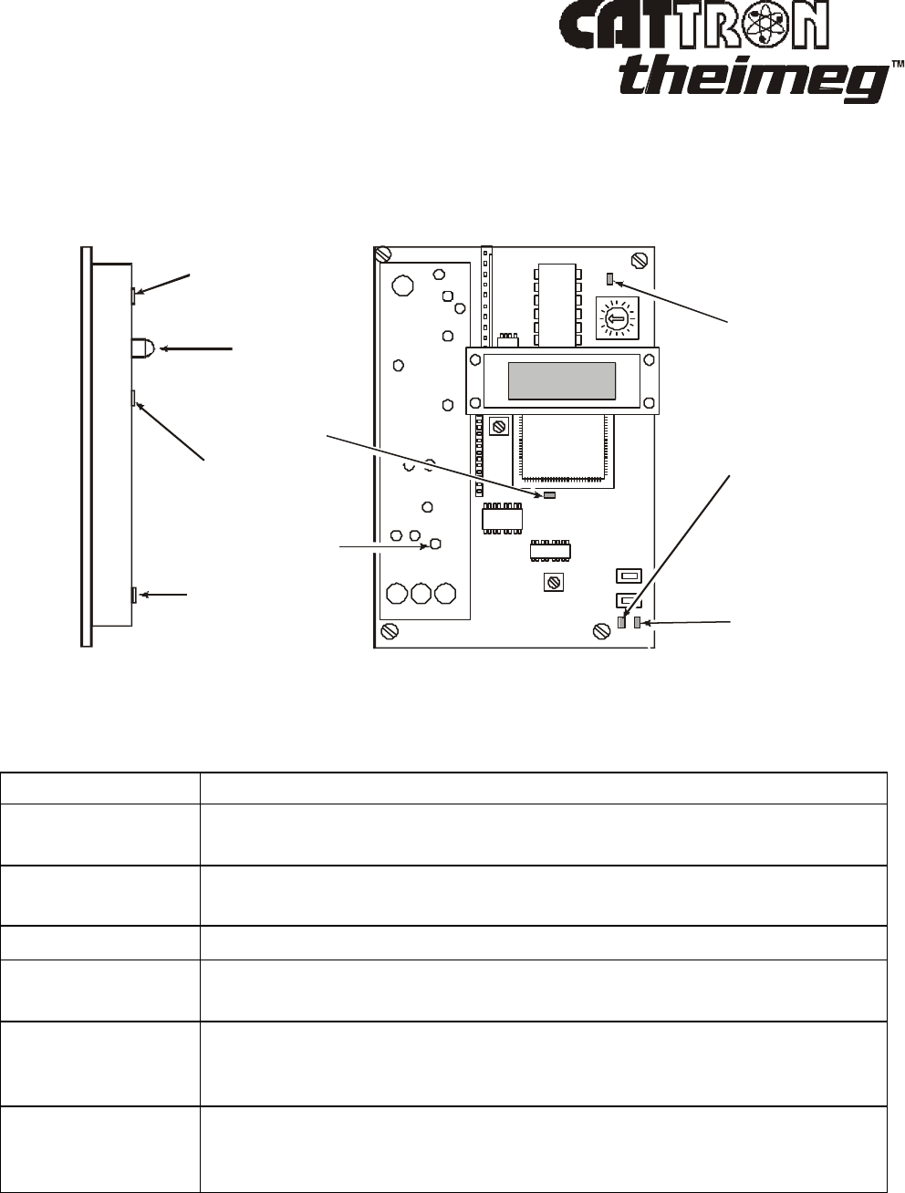
Transceiver Board, together with its ‘companion’ RF Power Amplifier Board. Referring to Figure
1-7 and Table 1-2 below, transceiver and amplifier board LED indicators indicate system status and are
particularly useful when troubleshooting and adjusting the transceiver.
Information to the User regarding FCC Compliance:
Changes or modifications not expressly approved by the manufacture could void the user's authority to
operate the equipment.
This device complies with Part 15 of the FCC Rules. Operation is subject to the following two
conditions; (1) this device may not cause harmful interference, and (2) this device must accept any
interference received, including interference that may cause undesired operation.
RF Exposure Information:
Installation of this RF device requires the antenna to be mounted in a manner that ensures a 36cm
minimum separation distance from the end user(s).

09/2003, CATTRON-THEIMEG™ Page 3 of 4
Radio Frequency (RF) Transceiver, continued.
Figure 1-7. R3HNX Transceiver & RF Amplifier Board LED Indicators
TRANSCEIVER BOARD
RF AMPLIFIER BOARD
VCO
LOCK
LED
TX
RX
DATA
LED
RF POWER
LED
TO ANT
TO RX
TO TX
Q-SYNC
LED
CARRIER
DETECT
LED
RECEIVER
POWER
LED
Table 1-2. R3HNX Transceiver & RF Amplifier Board LED Indicators
LED Description
Transceiver Power This red LED indicates the presence of DC power on the transceiver
circuit board.
Carrier Detect The green Carrier Detect LED indicates that the receiver section is
receiving a RF signal.
Data This yellow LED indicates that the received RF message contains data.
Q-Sync This orange LED indicates an interrupt that signifies the computer/
decoder has received a new message.
VCO Lock This red LED (located undernneath the EMI/RFI shield) illuminates when
the transceiver frequency synthesizer is unable to lock onto the required
frequency.
RF Power LED This red LED (located on the RF amplifier) flashes when the transmitted
digital RF ‘POLLING™’ data from the R3HNX transmitter is being
amplified and sent to the RCT

Page 4 of 4 09/2003, CATTRON-THEIMEG™
SYSTEM SUMMARY – Technical Specifications
LCU [RCR]
Enclosure: 20"L x 20"H x 8"W (50.80cm x 50.80cm x 20.32cm), NEMA 4
(IP66) Steel.
Weight: Approximately 70 lbs (31.75 kg)
Environment: Outdoors, -22°F to 150°F (-30°C to 65°C), RH 0 to 95% non-
condensing (-40°F units available – contact factory for details)
Electrical
Input/Output connections: Qty 4, quick connect/disconnect plugs and sockets
Solid State Digital Outputs: Total of 96 rated at 100VDC with individual fusing at 5A
Solid State Digital Inputs: Total of 48 rated at 74VDC with individual fusing at 5A
Electro-mechanical Outputs: 100VDC @ 10A
Output Termination: 2 screw terminals per I/O position
Receiver/Decoder Power Source: DC-DC converter; 24-78 VDC Input/13.8 VDC output @ 0.8 A
with Under/Over Voltage protection
Minimum Locomotive
Battery voltage: 62VDC
Micro-controllers Qty 3, Intel™ 8051 family microprocessors
Serial Communication Ports: RS232 port for GPS Receiver/clock and external event recorder
RS485 port for locomotive monitoring
Frequency Range: 447-473 MHz
Channel Spacing: 12.5 kHz
Emission/Modulation: 9K801FD ±2.5 kHz deviation
RF Transmit Power: 1.6W (factory set)
Range: 1-mile line of site
Antennas: Qty 2, 5 dB gain, coupled antennas, mounted vertically as a
broadside array for receive and transmit
Approvals: US FCC (Part 90)
Industry Canada (RSS119)
Receiver Sensitivity: 0.5 µV (20 dB quieting) typical
Frequency Stability: ±0.0005% of reference frequency
Decoder Microprocessor Speed: 11.059 MHz
Axle Generator: 120 PPR Dual Phase.
NOTE: As part of our ‘continuous improvement’ policy, CATTRON-THEIMEG™
reserves the right to change specifications without notice.