Cattron North America U915 LOW POWER TRANSCEIVER MODULE User Manual 9S01 U915 A201 TRX Integration Guide
Laird Controls North America Inc. LOW POWER TRANSCEIVER MODULE 9S01 U915 A201 TRX Integration Guide
Contents
- 1. Integration Guide
- 2. User Manual
User Manual

902-928MHz FSK version Introduction
Document p/n: 9S01-U915-A201, rev.2
Cattron-Theimeg Inc. Proprietary and Confidential 1-
1
Product
Development
TRX Integration Guide.
902-928MHz FSK version
Document p/n: 9S01-U915-A201, rev.2
CONFIDENTIALITY NOTICE
The information contained in this document is the exclusive, confidential and proprietary property of Cattron-Theimeg
Inc. It is not to be reproduced, nor is it or any portion of it to be used by or disclosed to any other individual or legal
entity, without the prior, written approval of Cattron-Theimeg Inc. Furthermore, the information contained within this
document is also to be handled in accordance with any and all confidentiality agreements between Cattron-Theimeg
Inc. and the user of this information.
2014 Cattron-Theimeg Inc.

902-928MHz FSK version Introduction
Document p/n: 9S01-U915-A201, rev.2
Cattron-Theimeg Inc. Proprietary and Confidential 1-
2
Revision History
Date Revision Description Signature / Date
5/23/07 1.0 Initial Version Prepared David A Stagg
Verified
Approved
02/15/14 2.0 Antenna information added for different
applications Prepared H. Lin
Verified
Approved
mm/dd/yy Prepared
Verified
Approved
mm/dd/yy Prepared
Verified
Approved
mm/dd/yy Prepared
Verified
Approved
mm/dd/yy Prepared
Verified
Approved
mm/dd/yy Prepared
Verified
Approved
mm/dd/yy Prepared
Verified
Approved
mm/dd/yy Prepared
Verified
Approved
mm/dd/yy Prepared
Verified
Approved
mm/dd/yy Prepared
Verified
Approved
902-928MHz FSK version Introduction
Document p/n: 9S01-U915-A201, rev.2
Cattron-Theimeg Inc. Proprietary and Confidential 1-
3
Table of Contents
1.
INTRODUCTION ............................................................................................................................................1-4
1.1.
P
URPOSE
..........................................................................................................................................................1-4
1.2.
S
COPE
..............................................................................................................................................................1-4
1.3.
D
EFINITIONS
,
A
CRONYMS
,
A
BBREVIATIONS
...................................................................................................1-4
1.3.1.
Definitions ..........................................................................................................................................1-4
1.3.2.
Acronyms ............................................................................................................................................1-4
1.3.3.
Abbreviations ......................................................................................................................................1-4
1.4.
R
EFERENCES
....................................................................................................................................................1-5
1.5.
O
VERVIEW
.......................................................................................................................................................1-5
1.5.1.
Notation Conventions .........................................................................................................................1-5
2.
OVERALL DESCRIPTION ............................................................................................................................2-1
2.1.
P
RODUCT
P
ERSPECTIVE
...................................................................................................................................2-1
2.1.1.
User Interfaces ....................................................................................................................................2-1
2.1.2.
Hardware Interfaces ............................................................................................................................2-1
2.1.3.
Software Interfaces .............................................................................................................................2-1
2.2.
P
RODUCT
F
UNCTIONS
......................................................................................................................................2-1
2.3.
U
SER
C
HARACTERISTICS
.................................................................................................................................2-2
2.4.
C
ONSTRAINTS
..................................................................................................................................................2-2
2.5.
A
SSUMPTIONS AND
D
EPENDENCIES
.................................................................................................................2-2
3.
SPECIFIC REQUIREMENTS ........................................................................................................................3-3
3.1.
E
XTERNAL
I
NTERFACE
R
EQUIREMENTS
..........................................................................................................3-3
3.1.1.
Interfaces.............................................................................................................................................3-3
3.1.1.1
50 Pin Header I/O. ..............................................................................................................................3-3
3.1.2.
Software Interface Requirements ........................................................................................................3-4
3.2.
S
YSTEM
F
EATURES
..........................................................................................................................................3-4
3.2.1.
EEPROM ............................................................................................................................................3-4
3.2.2.
Output Power ......................................................................................................................................3-4
3.2.3.
Software Configurable ........................................................................................................................3-4
3.2.4.
Low Cost TCXO .................................................................................................................................3-4
3.3.
P
ERFORMANCE
R
EQUIREMENTS
......................................................................................................................3-5
3.3.1.
Frequency Range ................................................................................................................................3-5
3.3.2.
Adjacent and co channel power ..........................................................................................................3-5
3.3.3.
Modulation ..........................................................................................................................................3-5
3.3.4.
Duty Cycle ..........................................................................................................................................3-5
3.4.
D
ESIGN
C
ONSTRAINTS
.....................................................................................................................................3-5
3.4.1.
Standards Compliance ........................................................................................................................3-5
3.4.2.
Mechanical Dimensions ......................................................................................................................3-6
3.4.3.
Power Requirements ...........................................................................................................................3-7
3.4.4.
Software Requirements .......................................................................................................................3-7
3.5.
S
YSTEM
A
TTRIBUTES
......................................................................................................................................3-8
3.5.1.
Reliability ...........................................................................................................................................3-8
3.5.2.
Availability .........................................................................................................................................3-8
3.5.3.
Security ...............................................................................................................................................3-8
3.5.4.
Maintainability ....................................................................................................................................3-8
3.5.5.
Portability ...........................................................................................................................................3-8

902-928MHz FSK version Introduction
Document p/n: 9S01-U915-A201, rev.2
Cattron-Theimeg Inc. Proprietary and Confidential 1-
4
1. Introduction
1.1. Purpose
This Document will provide the design constraints for the inclusion of the U915 TRX into a Cattron-Theimeg
Inc. product capable of meeting the requirements of FCC part 15, this module will be configured by software
and cover the frequency ranges of 902MHz to 928MHz. and power of up to 5mW.
Modulation schemes supported will be, 2FSK
1.2. Scope
• This document is to define the requirements for this TRX to maintain operation within FCC rules and
approved operation, to include.
• Transceiver interface.
• Supported protocols.
• Hardware target size.
• Software requirements.
• Operating band.
1.3. Definitions, Acronyms, Abbreviations
1.3.1. Definitions
• Anomaly. Anything observed in the documentation or operation of software that deviates from
expectations based on previously verified software products or reference documents. A critical
anomaly is one that must be resolved before the V&V effort proceeds to the next life- cycle phase.
• Third Party Testing. The verification testing required to be carried out by an authorized body.
1.3.2. Acronyms
• ETSI European Telecommunication Standards Institute
• EN European Norm (legal obligation)
• FCC Federal Communication Commission
• 2FSK Modulation consisting of two distinct states.
• SDD Software Design description
• SRS system Requirements Specification
• SVVP Software Verification and Validation Plan
• SVVR Software Verification and Validation Report
• V&V Verification and Validation
• EMC Electromagnetic Compatibility
• SRD Short Range Device
1.3.3. Abbreviations
none
902-928MHz FSK version Introduction
Document p/n: 9S01-U915-A201, rev.2
Cattron-Theimeg Inc. Proprietary and Confidential 1-
5
1.4. References
1. FCC Emission Mask
1.5. Overview
1.5.1. Notation Conventions
Throughout this document, functionality may be listed using the following syntactical conventions:
• The use of “shall” implies a requirement that must be implemented.

902-928MHz FSK version Specific Requirements
Document p/n: 9S01-U915-A201, rev.2
Cattron-Theimeg Inc. Proprietary and Confidential 2-
1
2. Overall Description
2.1. Product Perspective
This Radio module version is constrained to 902-928MHz, 0dBm to 5dBm, FSK modulation and some
restriction on maximum duty cycle if secondary antennas are used.
The Radio modules is to achieve full interchangeability between product model lines, maintaining mechanical
and software interfaces as well as physical dimensions is a general objective.
2.1.1. User Interfaces
All interface between this module and the User will be software controlled by the product hosting this
module. Features such as Frequency, Power and Modulation are all controlled by the Host device.
2.1.2. Hardware Interfaces
This product will have two hardware interfaces; these are the RF Port and a 50 pin I/O connector
carrying the microcontroller interface and power lines.
The 50 pin interface will have a
• 4 wire serial interface, consisting of Clock in, Data out, Data in and Load.
• Power: 3V3 and E2Prom 3-5V
• I2C interface to store personality.
• Data I/O 1 wire out 1 wire in
• Chip enable 1 wire.
2.1.3. Software Interfaces
This module will require the configuration of Data Registers by the operating firmware that set the
operating parameters.
The AE system will provide the operational parameters to the operating firmware.
• Frequency,
• Power,
• Tx/Rx Mode.
2.2. Product Functions
• The Product shall have the capacity to hold a permanent configuration file
• The Product shall be software configurable
• The Operating frequency shall be Programmable
• The Modulation Deviation shall be programmable
• The output power is programmable
902-928MHz FSK version Specific Requirements
Document p/n: 9S01-U915-A201, rev.2
Cattron-Theimeg Inc. Proprietary and Confidential 2-
2
2.3. User Characteristics
Operators: Require no knowledge of this part, all configuration is taken care of in the engineered product.
Technicians: The programming of this device is effected by the connected encoder, the encoder can choose to
program the device according to it’s own programming or it can take the configuration table from the eeprom
on the radio module.
Therefore the radio module may be independently programmed with the register table, or programmed by the
controller housing it.
2.4. Constraints
This subsection describes any items that limit the developer’s options. These include:
• FCC Part 15 rules
• EN301-489
• Interconnectivity compatibility with URM physical interface.
• Interconnectivity compatibility with URM programming interface.
• Physical size for interchangeability with Unity products and current Cattron Toggle and Paddle.
• RF Connector type MMCX
• Limitation of Human body exposure.
2.5. Assumptions and Dependencies
It is assumed that this device may need to be revised if any of the constraint’s change.
Any actual changes will require further FCC submissions for approvals.

902-928MHz FSK version Specific Requirements
Document p/n: 9S01-U915-A201, rev.2
Cattron-Theimeg Inc. Proprietary and Confidential 3-
3
3. Specific Requirements
3.1. External Interface Requirements
3.1.1. Interfaces
3.1.1.1 50 Pin Header I/O.
PIN Label Description
1,2 RFVBAT Switched Battery voltage - Not Used.
3,4 GND
5-14 N/C
15 SWD O/P, Sync Word Detect, Not Used
16-19 N/C
20 DATCLK I/O, Clock,
When in RX mode leading edge is synchronous with RX Data,
When in TX mode data is latched in on leading edge.
IF in UART mode used to output TX Data.
21 ENA I/P, Enable RF deck when High.
22 GND
23 PAON I/P, RF Power ON and switch to TX mode when High.
24 PLE I/P, Load Enable, Control Data is latched into registers when High
25 TRDAT Data I/O when synchronous, RX data OUT when asynchronous.
26 TXD TX in when asynchronous (Fit R35)
27 3V3 Regulated input for synthesizer.
28 3V3/5V Regulated input for E2PROM
29 N/C
30 PCLK I/P, Control Register Clock, data clocked on rising edge.
31 PDI I/P, Control Register data read in.
32 PDO O/P, Control Register data read out, MSB first.
33 RXD1 May be used to output Received Data (Fit R35).
34 MUX O/P, TRX status, Not Used.
35-37 N/U
38 SDA TRX E2PROM
39 SCL TRX E2PROM
40 N/U
41 G8 I/P, PA +8dB Gain, Not Used
42 N/U
43 G16 I/P, PA +16dB Gain, Not Used
44-50 N/U
3.1.1.2 RF Antenna Port
• MMCX type connector.
902-928MHz FSK version Specific Requirements
Document p/n: 9S01-U915-A201, rev.2
Cattron-Theimeg Inc. Proprietary and Confidential 3-
4
3.1.2. Software Interface Requirements
Software requirements are generally as required to implement the interface indicated above, more
specifically
The RXD and TXD lines will need to have a direct microprocessor interface with baud rates able to cope
with the maximum communication rate, a variable dependant on operating mode, this version is limited
to 4,000baud.
Power Amplifier control PA-ON may be implemented through a latch, (further power control is
available through the Synthesizer control registers.)
Standby will power down the RF device and can be implemented through a latch.
The I2C interface has no specific speed requirements but security of data transferred shall be verified.
3.2. System Features
3.2.1. EEPROM
Onboard EEPROM for storing one or more defined RF Personalities.
3.2.1.1. EEPROM Functional Requirements
• I2C Bus
• Memory Size 8KB
• CRC Data Protection HD>6
3.2.1.2. EEPROM Repository
The EEPROM on this module may be configured to hold a personality database of the registers
required for the synthesizer programming as well as various yet to be defined configuration data,
such information may include:
Power, including a gain calibration value.
Frequency , or a table of Frequencies
Skip frequency table
Data Format.
3.2.2. Output Power
• Synthesizer output power is programmable up to 5mW .
3.2.3. Software Configurable
• Synthesizer operation is software configurable, both in Transmit and Receive modes, refer to the
data sheet for full and up to date details.
3.2.4. Low Cost TCXO
• A low cost 10PPM TCXO is used.
902-928MHz FSK version Specific Requirements
Document p/n: 9S01-U915-A201, rev.2
Cattron-Theimeg Inc. Proprietary and Confidential 3-
5
3.3. Performance Requirements
3.3.1. Frequency Range
• 902MHz to 928MHz
3.3.2. Adjacent and co channel power
• To remain within FCC part 15 limits.
3.3.3. Modulation
• 2FSK Programmable deviation.
NB: The product of Modulating rate and Deviation shall not cause the FCC part 15 mask limits to
be exceeded.
3.3.4. Duty Cycle
• If the integral; antenna is used then no restriction exists on Duty Cycle.
• If either of the two specific 3dB gain antennas approved for use are used then a duty cycle limit
of 25% must be maintained.
3.4. Design Constraints
3.4.1. Standards Compliance
• EN301-489-3 EMC Immunity Short Range Devices
• FCC Part 15 @ 5mW, (normal keyed modulation applies)
• EN61000-6-2:2001 EMC Immunity
• SARS Human body exposure limits.

902-928MHz FSK version Specific Requirements
Document p/n: 9S01-U915-A201, rev.2
Cattron-Theimeg Inc. Proprietary and Confidential 3-
6
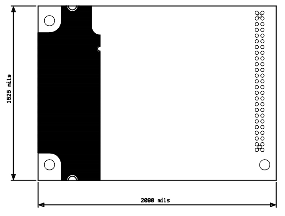
3.4.2. Mechanical Dimensions
U915 TRX outline

902-928MHz FSK version Specific Requirements
Document p/n: 9S01-U915-A201, rev.2
Cattron-Theimeg Inc. Proprietary and Confidential 3-
7
3.4.3. Power Requirements
There are two power sources required for operation
3V3: 3V+- 10% @ 100mA
3V3 EEPROM : 3V+-10% @ 100mA
3.4.4. Software Requirements
3.4.4.1. Overall Timing TX Mode
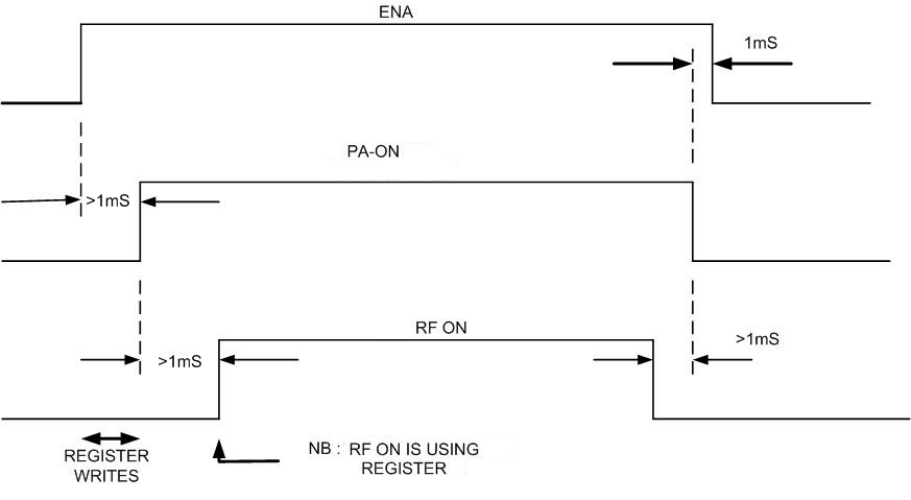
The control of the ENA, PA-ON, lines need to be sequenced to comply with the following general
sequence.
Overall Generalized Timing sequence
3.4.4.2. Register Program Sequence TX Mode
After CE low, Wait for regulator ready
Wait for >1mS for all to settle
1. Program Registers as defined in data sheet
2 Set PA_ON = 1 switches on PA, & Ant SW to TX, Wait 5mS
3 Program synth to TX power ON
4 Output Data
5 Program synth TX power OFF
6 Set PA_ON = 0 switch off PA, & Ant SW to RX,
7 Take CE low powers down RF deck
902-928MHz FSK version Specific Requirements
Document p/n: 9S01-U915-A201, rev.2
Cattron-Theimeg Inc. Proprietary and Confidential 3-
8
3.5. System Attributes
3.5.1. Reliability
All design aspect of this module shall be maintained within Agile along with all supporting
documentation and data sheets for future reference.
Maintenance of, Manufacturing, Re-design, Approvals and Testing and continuous improvement shall
fall within the requirements of the quality control system.
3.5.2. Availability
P.O.S.T and ongoing system checks should be employed to check system availability and continued
stability.
3.5.3. Security
The data within the onboard EEPROM, personality array shall be protected by a CRC with a HD>=6
3.5.4. Maintainability
As most aspects of this module are software configurable, little maintenance is likely to be needed,
Tuning is minimized
Specific configuration data may be stored within the Personality EEPROM.
Adjustments are minimal, and are limited to TCXO tuning.
3.5.5. Portability
It is envisaged that all Radio modules will be transferable between different encoders and decoders.
FCC WARNING STATEMENT
THIS DEVICE COMPLIES WITH PART 15 OF THE FCC RULES. OPERATION IS SUBJECT TO
THE FOLLOWING TWO CONDITIONS: (1) THIS DEVICE MAY NOT CAUSE HARMFUL
INTERFERENCE, AND (2) THIS DEVICE MUST ACCEPT ANY INTERFERENCE RECEIVED,
INCLUDING INTERFERENCE THAT MAY CAUSE UNDESIRED OPERATION.
NOTE: THE MANUFACTURER IS NOT RESPONSIBLE FOR ANY RADIO OR TV
INTERFERENCE CAUSED BY UNAUTHORIZED MODIFICATIONS TO THIS EQUIPMENT.
SUCH MODIFICATIONS COULD VOID THE USER’S AUTHORITY TO OPERATE THE
EQUIPMENT.
Only the following authorized antennas may be used with the equipment:
Childs 3DB-806
9D08-7833-A001
Nearson S467TR-915S
2PCA-8339-X501