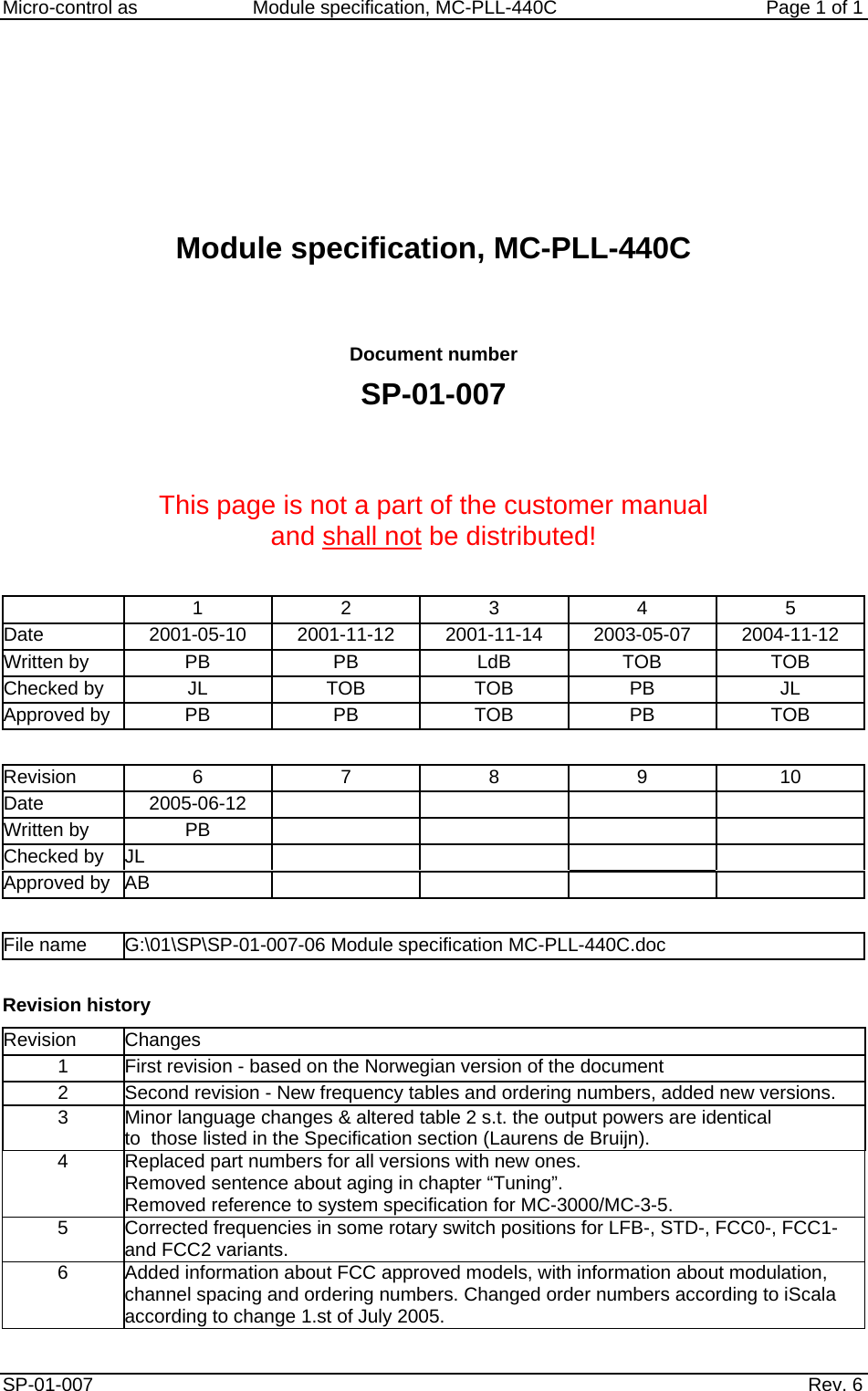
Cavotec Micro control as PLL-440C-FCC1 Industrial Remote Control Transmitter Module User Manual Module specification MC PLL 440C
Cavotec Micro-control as Industrial Remote Control Transmitter Module Module specification MC PLL 440C
UserManual.wiki
>
Cavotec Micro control as
>
PLL 440C FCC1 User Manual
Manual
Navigation menu
Upload a User Manual
Namespaces
Wiki Guide
HTML
PDF
Info
Views
User Manual
Discussion / Help
Navigation
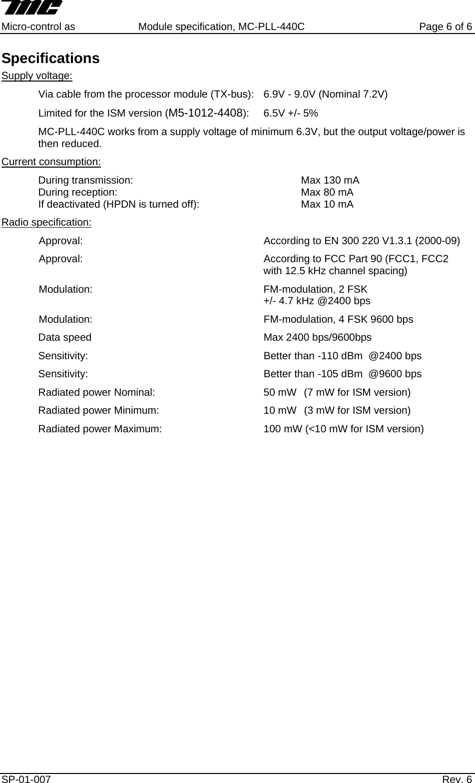
![Micro-control as Module specification, MC-PLL-440C Page 2 of 6 Module This module specification refers to the MC-PLL-440C. The module looks like this: Ref. Name See chapter J1 TX-bus Connections J2 Antenna connector Connections J3 Test connections Connections J4 Test connections Connections SW1 Rotary switch Configuration D24 RX-LED Green Indicators D25 TX-LED Red Indicators D30 RSSI-LED Green Indicators Micro−control asVersions The PLL-440C exists in several versions with various properties. Refer to the label at the module top in the field "ORD.NO". The format is changed from XXXXX to M5-1012-XXXX. The following text may be found: Output power [mW] Order no. Explanation Frequency[MHz] Channel separation[kHz] Min Nom. Max. M5-1012-4407 LFB (Low Frequency Band) 418 - 428 12.5 10 50 85 M5-1012-4405 Default version STD 433 - 443 25 10 50 85 M5-1012-4400 Version 0 FCC 440 - 450 12.5 10 50 85 M5-1012-4401 Version 1 with FCC approval. 450 - 460 12.5 10 50 85 M5-1012-4402 Version 2 with FCC approval. 460 - 470 12.5 10 50 85 M5-1012-4403 Version 3 FCC 470 - 474 12.5 10 50 85 M5-1012-4408 Version approved for ISM (Industry, Science and Medicine) band use. 428 – 438* 12.5 3 7 10 *The ISM band is limited to 433.075 - 434.775 MHz. In addition to these differences the various versions have different frequencies that may be chosen using the rotary switch, refer to chapter “Configuration”. Terms PLL-440C Short for MC-PLL-440CLED Light emitting diode SP-01-007 Rev. 6](https://usermanual.wiki/Cavotec-Micro-control-as/PLL-440C-FCC1/User-Guide-585147-Page-4.png)