Cazen SM-500 Wireless Water Level Control Device User Manual SMARTMISER BOOKLET 1 01
Cazen Enterprises LLC Wireless Water Level Control Device SMARTMISER BOOKLET 1 01
Cazen >
Contents
- 1. Important Information
- 2. SMARTMISER BOOKLET
SMARTMISER BOOKLET

INSTRUCTIONS &
INFORMATION
U.S. AND FOREIGN PATENTS PENDING
Congratulations on your Smartmiser purchase. To ensure
proper installation, please read these instructions completely
before installing your Smartmiser.
1.0 Mounting and Connecting the Receiver:
While the Receiver unit is weather resistant, it is not waterproof. Therefore, you
should choose a flat surface in a weather-protected area to install the Receiver.
Depending on obstructions between the units, the Receiver is designed to receive a
radio transmission up to 40 feet from the Transmitter. As the most common installation
location for the Transmitter is in the pool skimmer, (See Section 3) you will get
optimum performance from
the Smartmiser if the
Receiver is located within
35 feet of your skimmer and
is at least 4.5 feet above the
ground. Higher placement
will improve reception.
Remove the cover of
the Receiver. Using the at-
tachment screws provided,
mount the Receiver on to
the protected flat surface
using the two openings on
the top and bottom of the
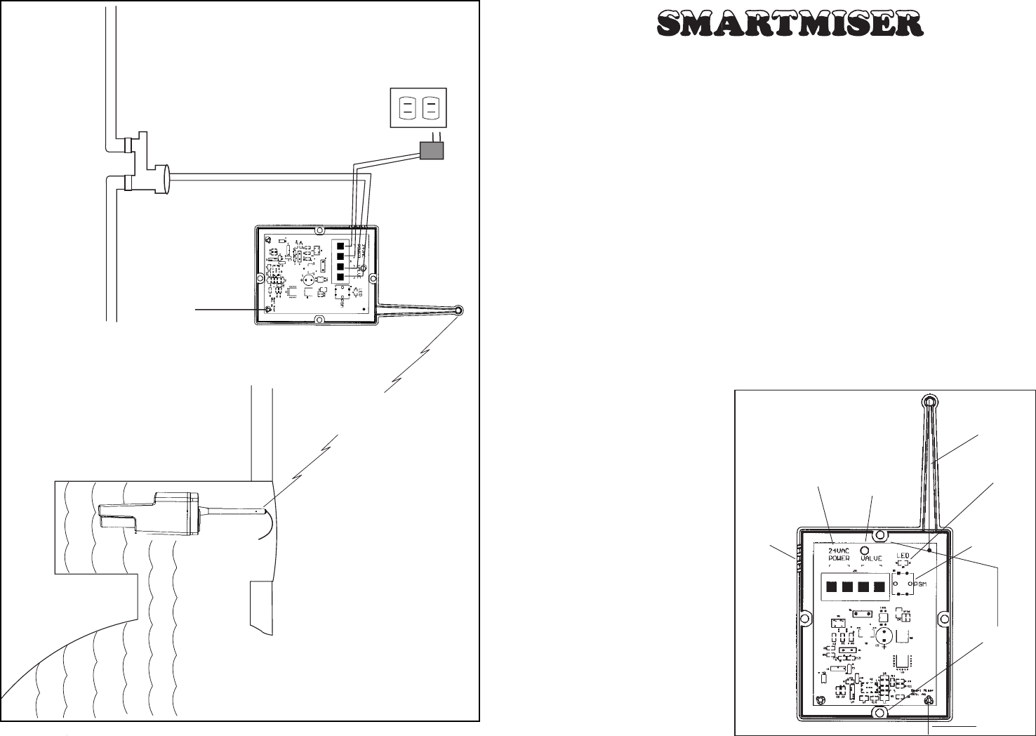
Receiver. Bend the dipole
antennae down towards the
ground. (See Figure 1)
™
COPYRIGHT 2000 POOLMISER PAGE 1
Figure 1
Mounting
Holes
PGM
Wire Slots
Valve
24 VAC LED Light
Antennae
Dipole
Antennae
PAGE 8COPYRIGHT 2000 POOLMISER
110 Volt
GFI 24 Volt
Transformer
RECEIVER
SKIMMER
TRANSMITTER
Pool
Water Line to Pool
Sprinkler
Valve
Radio Signal
Figure 5

We recommend that you use a weather protected 110-volt GFI outlet for the
Transformer. Using a portion of the 30 feet of 2 conductor wire provided, attach
2 wires to the connections on the Transformer and attach those 2 wires to the terminals
on the Receiver marked 24 VAC as shown in Figure 1. Plug in the Transformer. Press
the wires into the wire slots in the Receiver as shown in Figure 1. The LED light on the
Receiver will flash in a series of 4 short bursts which means the Receiver will
automatically shut off the water to the pool after 2 hours. See Section 5.3 for more
details.
2.0 Hooking up the Gate Valve:
It is now time to hook up the Receiver to a valve to fill the pool. For this
function, you will need to purchase a standard 24-volt sprinkler valve that can be
purchased at most plumbing and hardware stores, directly from Poolmiser, or your
local Poolmiser distributor.
If your pool is already plumbed with water, install the valve per manufacturer’s
instructions into the existing water line. Using the wire provided, connect two of the
wires to the terminals in the Receiver marked “valve” as shown in Figure 1. Press the
2 wires into the wire slots as shown. Use the wire nuts to attach the wires to the valve.
If you need additional wire, make sure to use 18-gauge wire rated for exterior and
underground use, which can be purchased from Poolmiser. If water is not plumbed to
your pool, you will need to have a water line installed. (See Figure 5)
3.0 Positioning the Transmitter:
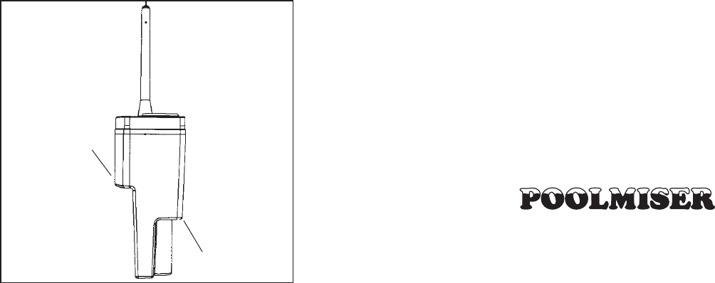
The Transmitter has two easily identifiable ledges which will help you
position the Transmitter in your pool. The top ledge is the approximate high water
PAGE 2COPYRIGHT 2000 POOLMISER COPYRIGHT 2000 POOLMISER PAGE 7
Figure 2
Top Ledge
High Water Mark
Low Water Mark
Bottom Ledge
mark and the bottom ledge is the
approximate low water mark.
(See Figure 2) Depending on the
water level of your pool, you
will attach the Transmitter either
higher or lower in the water
between these 2 ledges. If the
water level is at or near its low
point at time of installation, then
the Transmitter should be
installed with the bottom ledge
slightly out of the water. If the
water level is at or near its high
point at the time of installation,
the Transmitter should be
installed with the top ledge
slightly below the water.
4. The signal is sent and received but Possibly a problem with the valve. Re-
the water does not turn on. check wiring and connections from the
Receiver unit to the valve. Check the
solenoid on the top of the valve and replace
if necessary.
5. Water shuts off before the pool Possible that automatic shut off function is
level reaches the high water set for a smaller pool. Reset the automatic
indicator on the Transmitter. shut off function in the Receiver to a longer
time interval per Section 5.0.
For all other problems, either contact your pool installer or contact Poolmiser
directly and speak to one of our technicians.
307 Sixth Street
Petaluma, CA 94952
Tel. (707) 763-7613
Fax (707) 763-0353
8.0 FCC Information:
This device complies with Part 15 of the FCC Rules. Operation is subject to the
following two conditions: (1) this device may not cause harmful interference, and (2)
this device must accept any interference received, including interference that may cause
undesired operation.
This equipment has been tested and found to comply with the limits for a Class
B digital device, pursuant to Part 15 of the FCC Rules. These limits are designed to
provide reasonable protection against harmful interference in a residential installation.
This equipment generates, uses and can radiate radio frequency energy and, if not in-
stalled and used in accordance with the instructions, may cause harmful interference to
radio communications. However, there is no guarantee that interference will not occur
in a particular installation. If this equipment does cause harmful interference to radio
or television reception, which can be determined by turning the equipment off and on,
the user is encouraged to try to correct the interference by one or more of the following
measures:
∑Reorient or relocate the receiving antenna.
∑Increase the separation between the equipment and receiver.
∑Connect the equipment into an outlet on a circuit different from that to
which the receiver is connected.
Consult the dealer or an experienced radio technician for help.

PAGE 6COPYRIGHT 2000 POOLMISER COPYRIGHT 2000 POOLMISER PAGE 3
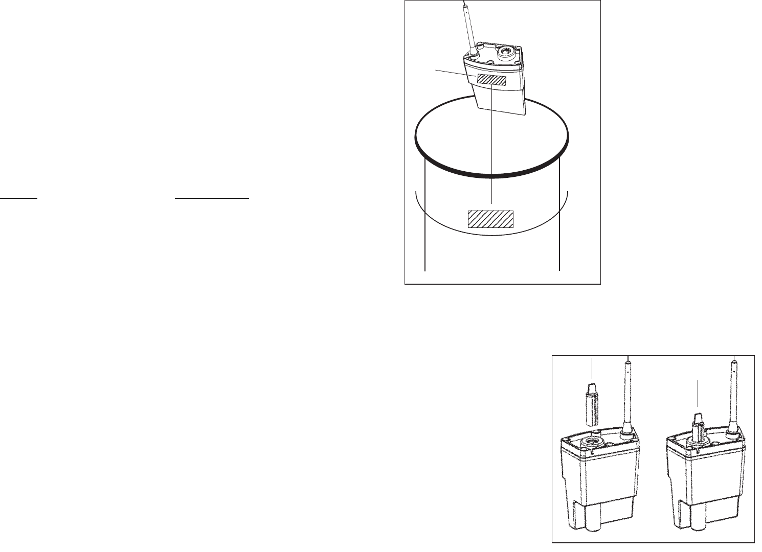
Figure 3
Velcro
Skimmer
Top
Water
Level
Attach Velcro
Here ▼
Transmitter antennae is flexible and will bend over when the Skimmer lid is replaced.
Do not change the length of the antennae. Now that the Transmitter is correctly
positioned, remove it from the Skimmer for the final step of programming.
4.0 Programming the Receiver and Transmitter:
▼
▼
Figure 4
Program the Receiver by
holding down the PGM switch for
approximately 3 seconds until the
LED light flashes quickly. (See
Figure 1) Insert the Float into the
Transmitter making sure to line up
the slot on the Float with the
corresponding tab on the top of the
Transmitter. (See Figure 4) Push
the Float into the Transmitter top
until it “pops” in. Holding the
Transmitter in an upright position
the Float will drop to the bottom
of the Transmitter unit. Hold the
Transmitter near the Receiver.
6.0 Cleaning the Skimmer Unit:
The Smartmiser has been designed to allow for easy removal to accommodate
cleaning the Skimmer basket. If you need to remove the basket from the Skimmer unit,
merely pull the Transmitter off of the velcro on the side of the Skimmer which will
allow easy removal of the Skimmer basket. Once the basket is replaced, merely re-
attach the Smartmiser to its previous location. However, remember that when the
Transmitter is removed, the Float may fall to the bottom of the Transmitter and may
turn on your water. If that occurs, make sure you promptly reinstall the Transmitter
after the Skimmer basket is replaced. Once the Transmitter is reinstalled, the water
level will automatically go off once the water reaches the high level indicator on the
Transmitter.
7.0 Troubleshooting:
Problem Possible Solution
1. The LED light is not blinking. Check for loss of power supply. Make sure
the Transformer is plugged in. Check to
make sure that the re-set button on the GFI
protected outlet is properly set.
2. The Receiver is not receiving the Possible loss of code signal. Re-program
Transmitter’s signal. the units to read each other per Section 4.0.
Possibly a problem with obstructions or
interference between the Receiver and
Transmitter units. Consider re-positioning
the Receiver unit closer to the Transmitter
or in a more direct line of sight, or allow
the top of the antenna to extend slightly
above the Skimmer through the hole in the
Skimmer lid. Consider placing the
Transmitter along the inside edge of the
pool instead of the Skimmer.
3. The Transmitter is not sending Possible loss of code signal. Re-program
a signal. the Transmitter and Receiver units to speak
to each other per Section 4.0.
Possible obstruction of Float. Check to see
that Float moves freely. Flush with hose
to clean.
Possible loss of power. Replace battery per
Section 5.1.
While the Transmitter can be
placed anywhere along the inside
edge of the pool, the preferred
location is in the Skimmer. Remove
the skimmer lid. You will note that
the curve of the Skimmer is the same
as the curve of the Transmitter.
Make sure that the portion of the
Skimmer above the water line where
you will place the Transmitter is dry.
Lightly sand the skimmer surface
and clean with alcohol (both
included). Peel off the back of the
matching velcro that is attached to
the Transmitter. Press the adhesive
back of the velcro against the
Skimmer as shown in Figure 3 and
let set undisturbed for at least
3 minutes. The height of the
Transmitter can be re-set at any time
by simply placing the Transmitter
higher or lower on the velcro
attached to the Skimmer.
Additional
velcro can be attached to the
Skimmer if necessary.
The

After approximately 6 seconds, the rapid flashing of the LED will stop. This
means that the Transmitter and the Receiver have randomly selected a code and
are now programmed to speak to each other. This programming will keep your
Smartmiser from accidentally activating a neighbor’s Smartmiser. You may re-set the
programming function at any time by repeating these steps. Insert the small filter into
the top hole of the Transmitter. Now replace the Receiver cover and reattach the
Transmitter in the skimmer.
You may now replace the top of the skimmer. For better reception, you can
allow the top of the Transmitter antennae to slightly extend through one of the holes in
the Skimmer lid. Your installation is now complete.
COPYRIGHT 2000 POOLMISER PAGE 5
5.0 YOUR SMARTMISER PARTS:
5.1 The Transmitter:
The Transmitter senses the water level in your pool. When an “on” signal is sent
from the Transmitter, the Receiver turns on the water to your pool. When the water
level rises approximately 1 inch, the Transmitter will send an “off” signal and shut off
the water.
The Transmitter can be opened by removing the six socket head cap screws, but
should be opened only to replace the battery which is a 3-volt lithium coin cell (CR
2032). By carefully lifting the Transmitter cover, the circuit board will slide out of the
base. Gently rotate the board to expose the top
of the battery for replacement. Then slide the
board back into the base, being careful not to
damage any electronic components. Normal
battery life should be from 2 to 3 years under
normal use. Be sure to replace a worn battery
in the Transmitter as failure to do so will cause
the Smartmiser to stop working and could
result in serious damage to your pool
equipment. Be sure to reprogram the unit
whenever the battery is replaced. (See
Section 4) The Transmitter unit is waterproof.
Whenever the lid of the Transmitter is
removed, the six screws should be reattached
applying even pressure to make sure that a
completely waterproof seal is achieved.
Modifications to the Transmitter,
including changes to the length of the
antennae, are prohibited and will void the
purchaser’s authority to use this device
(47CFR15). The Transmitter
PAGE 4COPYRIGHT 2000 POOLMISER
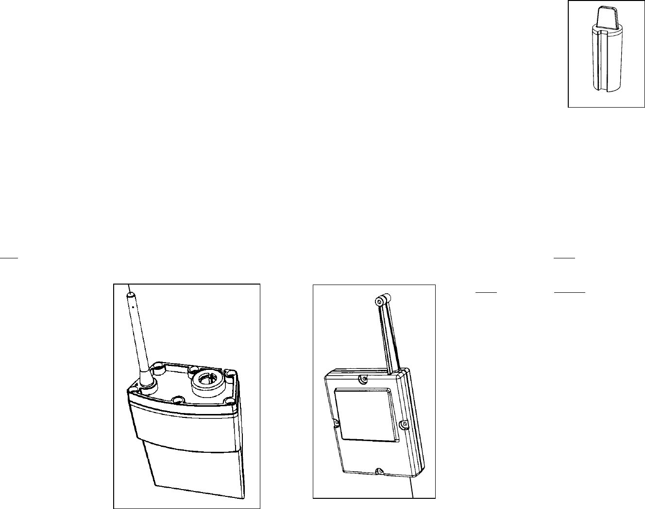
5.2 The Float:
The Float contains a small magnet which activates the
Transmitter unit. The Float moves up and down with the
water level in your pool and moves between the off and on
switches within the Transmitter. The Float will be inserted
into the top of the Transmitter unit as described in Section 4 of
the Instructions.
The Float
The Receiver
5.3 The Receiver:
The Receiver reads the signal from the Transmitter and either turns on or off the
water to your pool. Once an “on” signal is received, the Receiver automatically begins
to time the filling process. If for some reason the Transmitter does not send an “off”
signal, the Receiver is pre-set at the factory to shut off automatically. This automatic
shut off function has six different settings and can be changed from 10 minutes to 24
hours. The number of flashes of the LED light indicates the length of time before the
Receiver automatically shuts off the water.
Four flashes is pre-set at the factory and will automatically shut off the water
2 hours after an “on” signal is received. Pushing the PGM switch (See Figure 1) will
change the length of time on this safety shut off feature. Each quick press of the PGM
switch will advance the time function as follows:
Time Flashes
2 Hours 4 Flashes
8 Hours 5 Flashes
24 Hours 6 Flashes
10 Minutes 1 Flash
30 Minutes 2 Flashes
1.25 Hours 3 Flashes
Larger pools should be set for a longer time
interval.
5.4 Miscellaneous Parts:
Your Smartmiser package also contains a
standard 24-volt UL rated Interior Use
Transformer, mounting screws, extra velcro, 30’ of
2 conductor wire, and 2 wire nuts. The velcro is
used to mount the Transmitter unit into your pool.