Capture Reference Manual Version 23.0 Rev A User
Capture Reference Manual Version 23.0 Rev A CAPTURE Reference Manual Version 23.0 Rev A CAPTURE Reference Manual Version 23.0 Rev A 11203 ItemRelatedFiles cdb
Capture Reference Manual Version 23.0 Rev A CAPTURE Reference Manual Version 23.0 Rev A CAPTURE Reference Manual Version 23.0 Rev A 11204 ItemRelatedFiles cdb
Capture Reference Manual Version 23.0 Rev A CAPTURE Reference Manual Version 23.0 Rev A CAPTURE Reference Manual Version 23.0 Rev A 11205 ItemRelatedFiles cdb
2017-05-26
User Manual: Cdb Capture Reference Manual Version 23.0 Rev A CAPTURE Reference Manual Version 23.0 Rev A 11202 ItemRelatedFiles
Open the PDF directly: View PDF ![]() .
.
Page Count: 83

REFERENCE
MANUAL
Updated for Version 23.0
Revision A

© Capture Visualisation AB 2017
www.capturesweden.com
3
Table of ConTenTs
INTRODUCTION 5
The license key le ............................................ 5
Library updates ................................................. 6
Support ............................................................. 6
Demo version limitations ................................... 6
SOFTWARE OVERVIEW 8
The Capture Interface ....................................... 8
Main menu ........................................................ 8
Software Options .............................................. 9
Simulator View Settings .................................. 10
Simulator Settings ........................................... 12
The Navigator .................................................. 12
The Project Window ........................................ 16
Atmosphere Settings....................................... 16
Rendering Settings.......................................... 17
OBJECT MANIPULATION 19
Object Manipulation ........................................ 19
Adding objects to the project .......................... 20
FIXTURES 25
Fixtures overwiev ............................................ 25
DMX Universes................................................ 28
Fixture Settings ............................................... 29
Custom Gobo/Color Wheels ........................... 30
The Fixture Tab ................................................ 30
MATERIALS 33
Using Materials ............................................... 33
Mapping Materials .......................................... 35
MEDIA FIXTURES 37
Video Projectors & Digital Lights ..................... 37
Video Players .................................................. 39
Using CITP Media Sources ............................. 40
Controller & Media Server Connectivity .......... 41
NDI Video Sources .......................................... 41
LED SCREENS 43
Using LED Screens ......................................... 43
LAYERS & LAYER SETS 47
Using Layers ................................................... 47
Using Layer Sets ............................................. 49
SCENES 51
Using Scenes .................................................. 51
PLOTS & PAPERWORK 54
Plots ................................................................ 54
Plot Options .................................................... 55
Fixture Properties with Plots ........................... 56
Plot Styles ....................................................... 57
Exporting Plots ................................................ 58
MODEL IMPORT 61
DATA IMPORT AND EXPORT 63
MOTION CONTROLLERS 65
Adding a DMX Mover ...................................... 66
Adding a DMX Rotator .................................... 70
Patching a DMX Motion Controller ................. 72
SNAPSHOTS & VIDEO RENDERING 74
Snapshots ....................................................... 74
ADVANCED FILE MENU FUNCTIONS 76
Using the Import Model tool ........................... 76
Using the Import Data Tool ............................. 77
Drawing le format interchange ...................... 77
Using the Export Data Tool ............................. 78
Using the Export Focus Sheets Tool ............... 78
Update Library ................................................ 79
TROUBLESHOOTING 81
Troubleshooting............................................... 81
TABLE OF CONTENTS

INTRODUCTION TO CAPTURE
5
InTroduCTIon To CapTure
INTRODUCTION
This manual should serve as one of the primary tools
for installation and operation of the Capture software.
Capture Sweden’s e-mail support and online web forum
are available as important complements to this manual.
http://www.capturesweden.com
Please visit our website for regular software updates and
important product information. Also make sure to notify us if
your e-mail address is changed, since e-mail is our primary
communication channel.
Microsoft Windows
Capture is distributed with a Microsoft Installer (.msi)
package available from our web site. Once you have down-
loaded the installation package, simply double click it to
launch the installation.
macOS installation
Capture is distributed as an “.app” package inside a .DMG
(Disk Image) available from our website. Once downloaded,
it can be run from any location. When run, the latest version
of the library is automatically installed if necessary (hence
it’s possible to have multiple versions on a system, but they
will all always use the latest version of the library).
The license key le
Capture licenses are offered on a personal basis, which
means that it is possible to use the key-le on more than
one computer. As a result of that, it is also necessary to
unlock the key-le on each computer, so that we can keep
track of your Capture installations.
If you have purchased a Capture license and received a
key le, you will need to install it. This is done from inside
Capture; Open the Licensing dialog from the Tools menu
and click on the Install key le button. Once you have chosen
the license key and it has appeared in the window, choose
either ‘Automated unlock’ or ‘Manual unlock’ if you are not
connected to the Internet.
The manual unlocking process may take some time as it
requires manual attention from the Capture Sweden staff,
but we will help you as promptly as possible.

6
InTroduCTIon To CapTure
Library updates
Library updates are continuously available on our website,
http://www.capturesweden.com. If you have requested
library additions, this is where you will download an updated
library package when we have notied you of completion
of your request. Each release of Capture also contains the
latest available library package.
Support
Support to our customers is offered through e-mail and our
online web forum at http://www.capturesweden.com. Under
extraordinary circumstances we may also communicate
with you over telephone, Skype or MSN.
For fastest possible assistance, please make sure to e-mail
us at the appropriate e-mail address.
For questions regarding functionality or operation:
support@capturesweden.com.
For questions regarding the library or if you are missing x-
tures: library@capturesweden.com.
Here are some things we will always ask you to do before
helping you out:
• If you are a Microsoft Windows user, make sure that you
have all the latest applicable service packs and hotxes
from Windows Update.
• If you are a Microsoft Windows user, check that you have
the latest drivers for your computer components and your
graphics card in particular.
• Check that you have installed the latest version of Capture
and the latest library update.
Demo version limitations
The demo version of Capture comes with two (and no other)
limitations:
• The Save function is disabled.
• The software will only run for 90 minutes.
• There are no limitations in terms of console or media
server connectivity or the number of universes available for
visualization.

SOFTWARE OVERVIEW
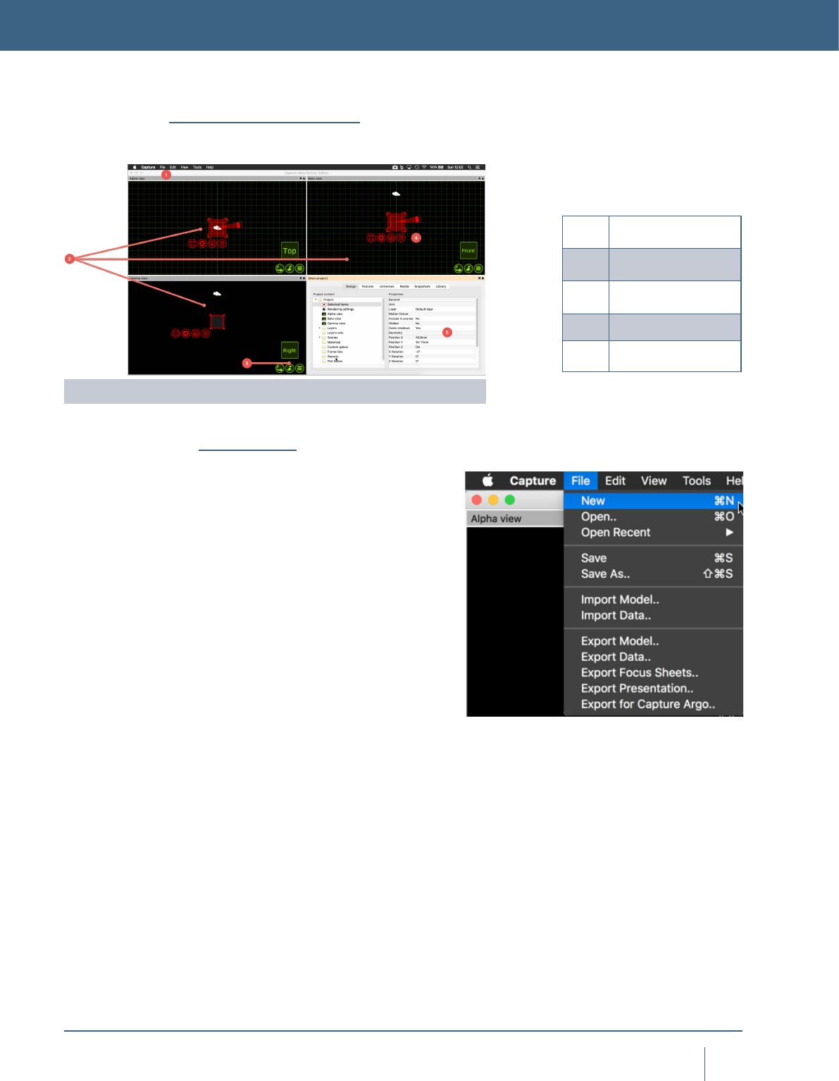
8
sofTware overvIew
SOFTWARE OVERVIEW
1Main Menu
2Simulator Views
3Simulator settings
4Navigator
5Project Window
The Capture Interface
Main menu
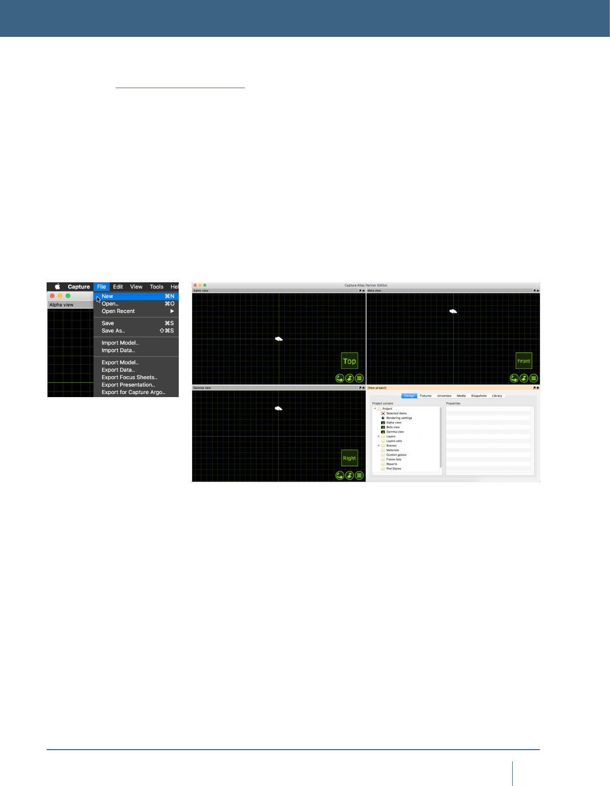
The main menu is available at the top of the main window. It
has been kept minimal in order to reduce confusion.
In the File menu you will nd the basic commands
for opening, saving and closing Capture project les.
Note the variety of different options are available for opening
older Capture project les.
The Import Model feature is used to open up other
project les in parallel and allows you to copy items from
other projects into the project you are working with (which is
done using the arrow navigator button).
The Import Data feature allows you to import a variety
of drawing formats from other programs, as well as specic
project data such as xture patch, weight, etc.
The Export Presentation feature that allows you to
create an executable le that will launch your project, wich
is embedded in the executable le, and show the Alpha
view. Presentations cannot be used to edit project les, they
merely serve as a viewing and presentation tool.
The Export for Capture Argo function allows you to
export a copy of your Capture Atlas le, for use in the previ-
ous Argo version.
The Export focus sheets feature creates a set of images,
one per xture (or as congured in the conguration dialog
presented), giving you a view out through the aperture of
the xture. It requires you to pick a folder into which the
images are placed.
In the Edit menu you will nd access to the unlimited
Undo and Redo commands.
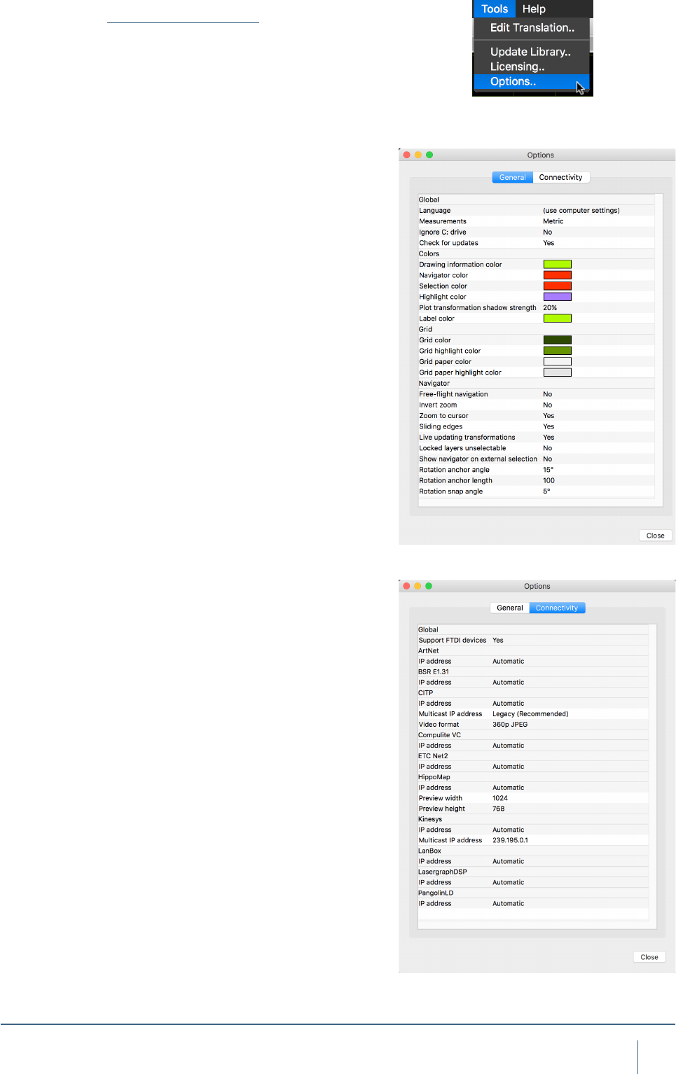
The Tools menu gives you access to the Options window
and the Translation window.
The main areas of the Capture Interface.
9
sofTware overvIew
Software Options
The software options are available through the
Tools / Options menu command and are split in three cate-
gories - General, Visualization and Connectivity.
Under the General tab you can change the language of
the user interface in Capture. By default it will follow the set-
tings of your computer.
The Ignore C: drive options is important on Microsoft
Windows machines that have their Windows installation on
a drive other then C : \
Turning on the Live updating transformation option
causes all simulation views to update at once when moving
or rotating objects.
Locking layers is a useful way of preventing accidental
modication of xed items such as the house of your venue.
The Locked layers un-selectable option takes it one step
further and prevents you from even selecting such items.
The Show navigator on external selection is a feature
from users with controllers than are capable of selecting x-
tures. Unless this option is enabled, xtures selected from a
controller will only highlight as red and not display the navi-
gator with the command buttons.
The size of the navigator’s rotation anchor can be
changed with the Rotation anchor angle and Rotation
anchor length options. The snapping rotation angle can be
set with the Rotation snap angle option.
The navigator’s snap function is enabled with a small
delay to prevent accidental snapping as well as giving the
user an option whether to snap items together at all or not.
This delay is set with the Snap timeout option.
The Connectivity tab contains options for controller
and media server connectivity. It can be important to set
the Preferred network address on a machine with multiple
network addresses, but unless you are connecting to older
equipment it is not encouraged to enable the Compatible
CITP mode as it may make it impossible to connect to newer
equipment.
You may also alter the incoming video format for CITP
communication.
By default, Art-Net, sACN (E1.31), Compulite VC, ETC
Net 2, HippoMap (HMap3), Lan Box, Lasergraph DSP and
PangolinLD are all set to Automatic. On rare occasions
when a machine has more than one network adapter, it may
be necessary to change Automatic to a specic IP address
available under the relevant protocol.
Connectivity Options may also be accessed by right
clicking in the External Universes section of the Project
Window.
10
sofTware overvIew
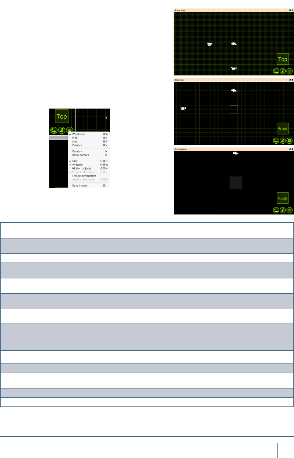
Wireframe Wireframe is the default view and works as a 3D CAD wireframe view whereby a user
can orbit any object in 3D but it is only rendered in wireframe.
Plot Replaces the Paper view from previous Capture versions. This view is used to make
plots.
Live Live 3D rendering view
Custom In Custom mode, you can congure your own look view with either wireframe/solid,
perspective/orthographic etc.
Camera Camera shows a list of preset camera positions for quick navigation, as well as the
ability to launch one of the user made camera positions.
Store Camera By positioning the camera to a user dened location, a user can then go to the Store
camera option and choose a camera preset to store the current camera pose to.
Grid Grid toggles the grid on/off for the selected view.
Widgets Widgets (such as the camera) can be toggled on/off for the selected view.
Hidden Objects Hidden objects can be toggled on/off for the selected view.
Project Information Toggles the project information on/off for the selected view.
Fixture Information Fixture information replaces the previous Live Information option from Capture Argo. It
overlays xtures with programming information like shutter and color mix status.
Quality Information Toggles the FPS and quality info on/off for the selected view.
Save Image.. Save an image of the currently selected view.
Simulator View Settings
Capture has three simulator views, Alpha, Beta and
Gamma. They can be congured to your liking, the next
section will discuss the available modes and options avail-
able for the views. Unlike previous Capture versions, all
simulator views now work in 3D. Meaning than no matter
the mode the view is in, you can orbit and pan around in
3D, doing away with the need for the different orthographic
modes from Capture Polar and Argo.
As discussed in the previous section, Capture has three
simulator views. These views can be congured to the users
liking. Conguring a simulator view is done by clicking on
the green list button as show below.
11
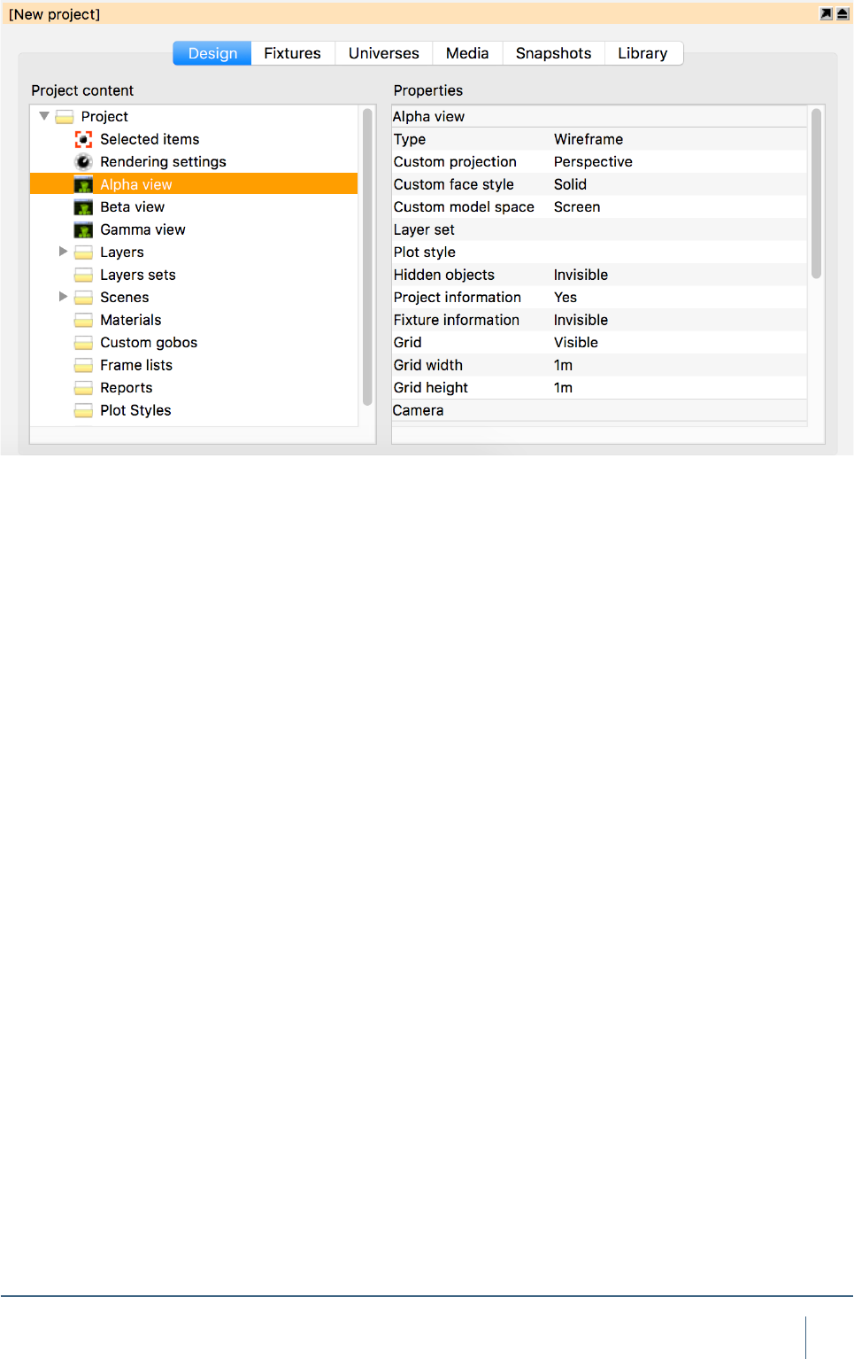
sofTware overvIew
Some view settings are not available in the navigator.
Additional settings for each are available in the Design tab
of the Project window. There is one item per view on the
left hand side, and when selected, more properties appear
on the right hand side.
The Layer set property allows you to choose the layer
set to use for ltering out layers in the view (when empty, no
layer ltering is performed).
The Grid width and Grid height properties determine
the distance between grid lines.
The Vertical eld of view property lets you control lens
angle of the view’s camera.
The Aspect ratio of a view can be set to follow 4:3 as
well as 16:9.
The Brightness, Exposure and Atmosphere set-
tings controls the look of the view when in Live mode.
If you have enabled the “Simpler Graphics” option of
Capture, Brightness and Exposure are replaced with
Fixture Lighting and Fixture Lighting Differentiation.
12
sofTware overvIew
Simulator Settings
It is possible to control a view using DMX. This is achieved
by either manually assigning a Patch universe / channel, by
dragging the view from the left hand side of the Design tab
to a channel in a universe view, or by dragging the view’s
camera from a simulator view to a channel in a universe
view. The Patch mode option can be used to select the
number of channels used by the camera.
Channel Function Channel Function
1 X Course 10 Tilt Fine
2X Fine 11 Pitch Course
3Y Course 12 Pitch Fine
4Y Fine 13 -
5Z Course 14 Ambient
6Z Fine 15 Lighting
7Pan Course 16 Atmosphere
8Pan Fine 17 Layer Set*
9Tilt Course 18 Scene*
* 0-3 Slot 1... 4-7 Slot 2… 252-255 Slot 64
Layer Set and Scene control needs to be additionally congured with their
“Control Slot” Properties. It is possible to choose between 64 Layer sets
and 64 Scenes.
Red - Manipulation
Green - Navigation
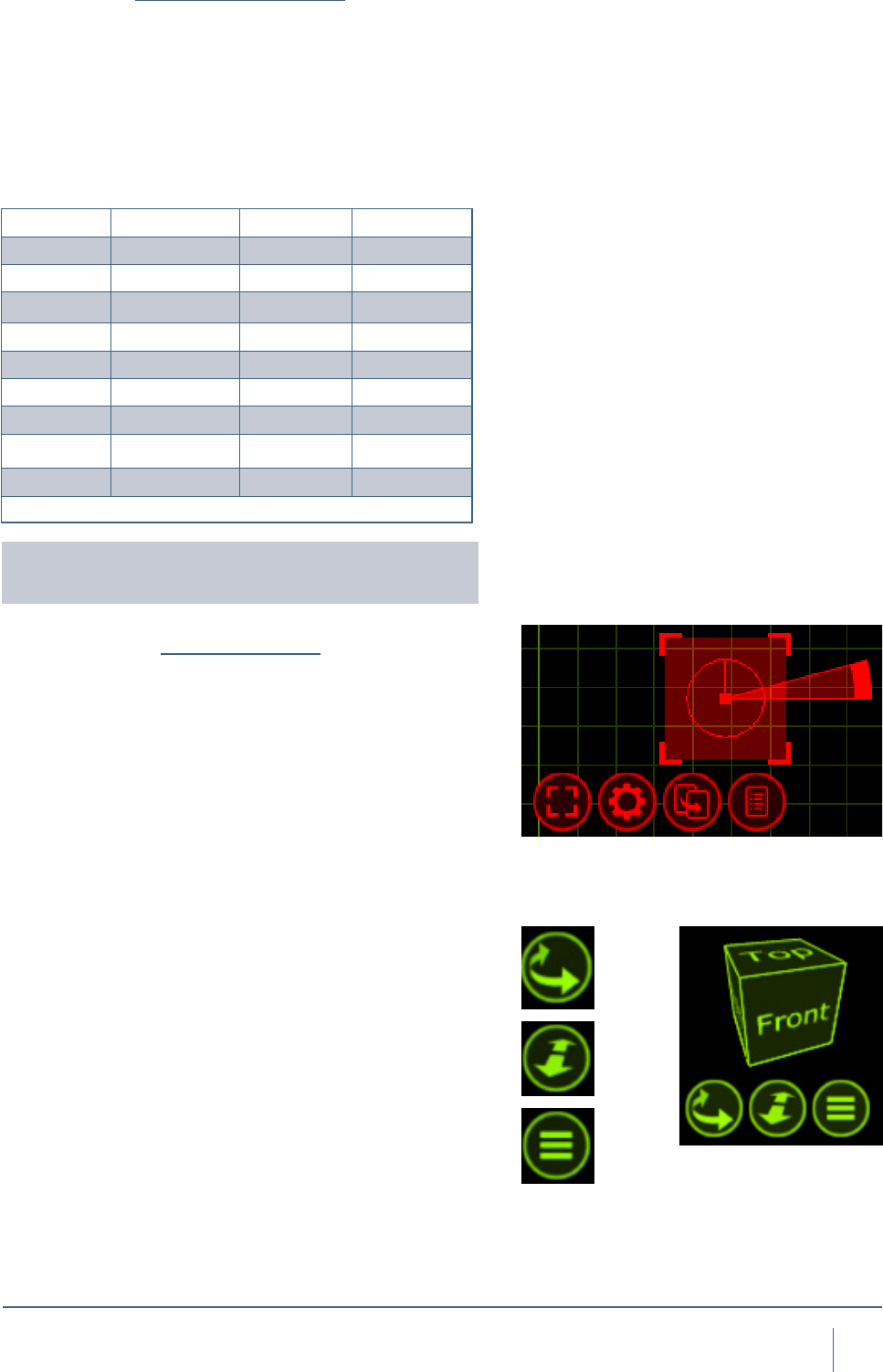
The Navigator
The Navigator is one of the main tools of capture. It is used
for two primary functions - Navigation and Manipulation. The
Navigator is present in the bottom right corner of the Alpha,
Beta and Gamma views. This Navigator is used to manipu-
late the view in terms of changing the camera viewing point
and zoom within the view as well as accessing the view
settings via the spanner button.
As mentioned, the Navigator located bottom right of the
views is primarily used for camera manipulation.
The First button, a curve with arrows, allows you to move
around a view. Holding the Shift or Ctrl keys allows a differ-
ent style of movement in the 3D views.
The second button is used to zoom in and out on the se-
lected view. Holding the button and moving the mouse up
or down will control the amount the camera is zoomed in
or out.
The third button is used to access the settings for the se-
lected view as we discussed earlier. Additional settings for
each are available in the Design tab of the Project window.
Whenever you select any objects, within any of the Alpha,
Beta or Gamma views within Capture; a second type navi-
gator appears. When objects are selected, they appear red
13
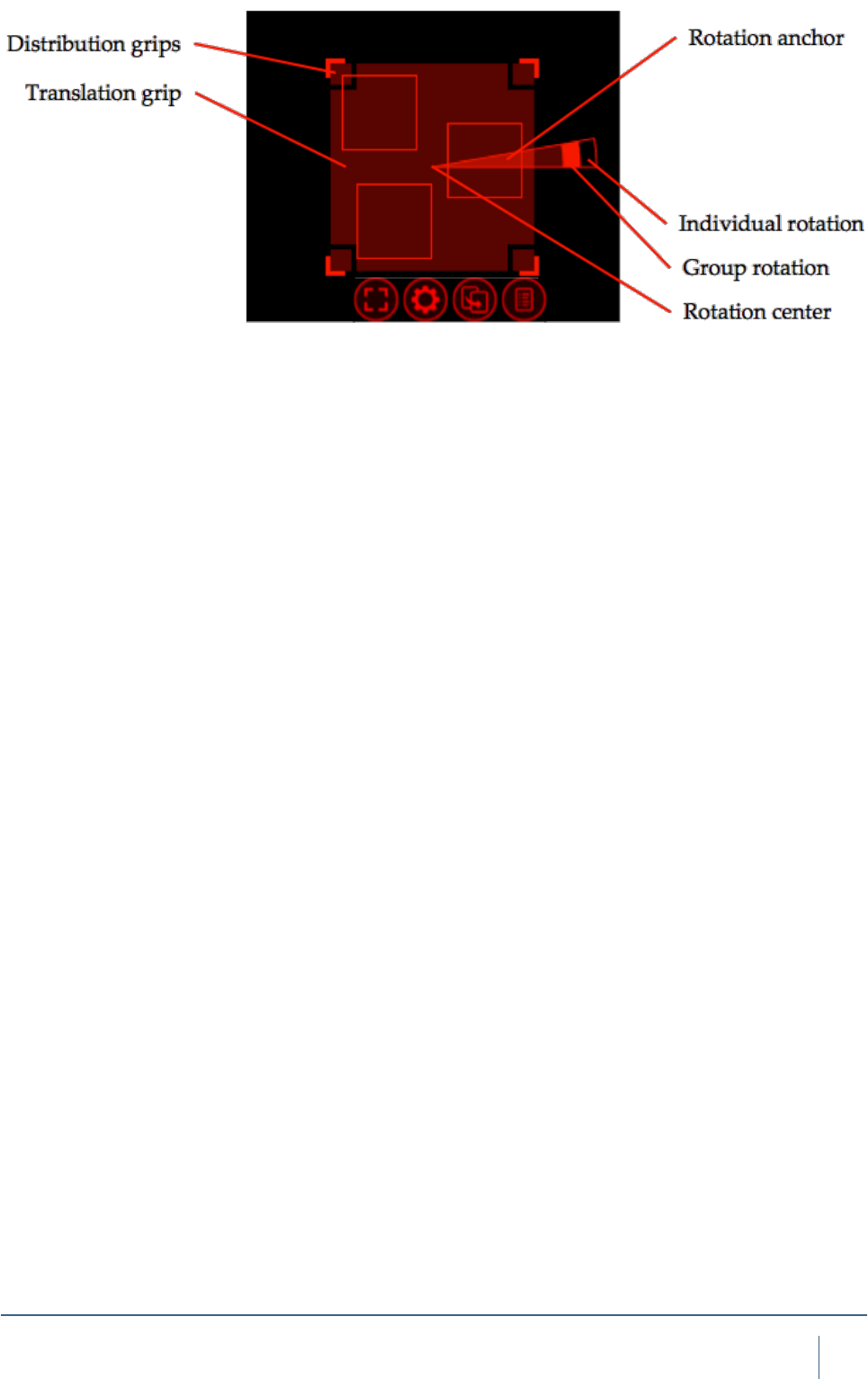
sofTware overvIew
with a a red grid around them that has some control buttons
below it. This second type of navigator is used to assist in
the manipulation of the objects.
Objects can be selected by clicking on them with the
mouse. Use the Shift key to add objects to the selection and
the Ctrl key to toggle individual object selection on and off.
By click-dragging the mouse over a group of objects, you
can select them all at a time. If you drag from the left to the
right, the objects must lie completely within the region, but if
you drag from the right to the left, it is enough for the objects
to be partially inside the region in order to become selected.
Clicking and moving the mouse anywhere inside the
Translation grip allows you to move objects around. This
area is intentionally large so that it is easy to move items.
While moving items, you can enable the ortho mode by
pressing Shift key. Snapping in the sense of bringing items
to a minimal distance is built in and activated during any
translation, but is not triggered until after a short delay. When
snapping is activate, the result of the snapping is illustrated
with an alternate colour.
Clicking and moving the mouse inside a Distribution grip
will allow you to spread out or bring together the selected
objects over the given area in a proportional manner. The
ortho mode is available here by using the Shift key as well.
The Rotation anchor is used to rotate objects. It can be
moved around to dene the center of rotation and allows
for both Individual rotation and Group rotation. Pressing the
Shift key enables snapped rotation.
14
sofTware overvIew
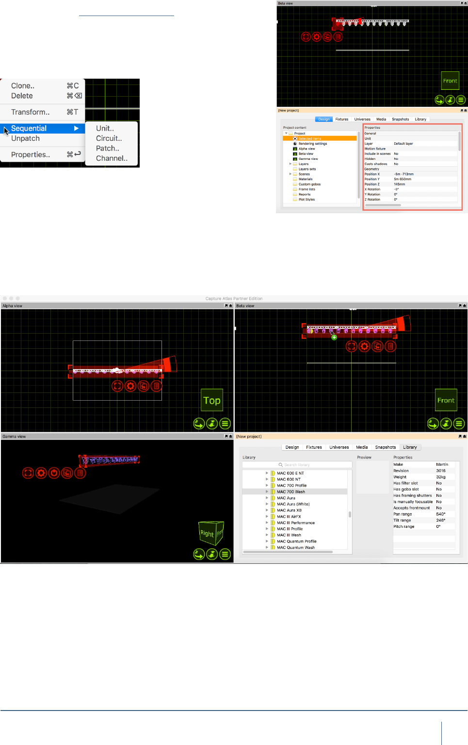
The rst button is a select/deselect button. It allows you to
select or deselect everything, with the added “layer” option.
Using the “layer” option will allow you to select or deselect
everything but only in the current layer. Layers will be dis-
cussed in a later chapter.
The second button is another options button, but in this in-
stance, pressing it displays a small list of possible opera-
tions relevant to the selected object(s). The list that appears
is context sensitive, that is to say that selecting a Lighting
Fixture will display different options in the list than that of a
Truss. Each available option/command will be covered later
in the relevant chapters.
The arrow button is used to drag objects out of one view to
another. Using this button, the objects won’t actually move
per say. The button is used primarily for patching xtures.
Select multiple xtures in the order you wish to patch them
and use the drag button to drag them onto a universe in the
project window or on an open universe window. This func-
tionality will be covered later in the relevant section.
You may also use the arrow button to drag the object to a
new location in the same window, thereby making a copy.
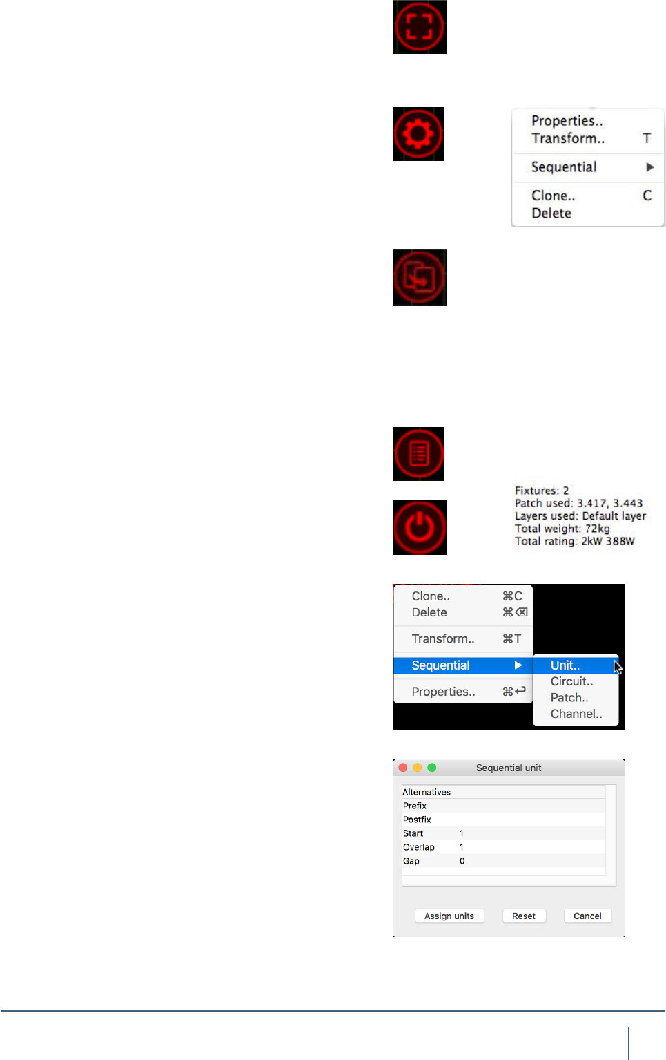
The button with a list is the Quick Summery button. Pressing
it when you have objects selected presents a popup window
about the selected objects displaying key data about them.
This button reveals the xture control pane and is only
visible when at least one lighting xture is selected and the
view is in Live mode.
Sequential Unit
This command allows you to set the Unit property of the
selected objects in a consecutive manner. You may specify
a Prex as well as a Postx to the numbering. The Start
property denes the rst number of the range. The Overlap
property allows you to create series such as 1, 1, 2, 2, 3, 3
and the Gap property allows you to create series such as
1, 3, 5, 7. Notice that if you select objects manually one by
one, this denes the order for the numbering. However, if
you select them by dragging the mouse over the objects, the
order of the objects undened.
Sequential Circuit
Sequential circuit essentially works just like sequential
uniting – except that you assign circuit numbers to the
Channel property of xtures. You may specify a Prex as
well as a Postx to the numbering.
Sequential Patch
This command allows you to sequentially patch xtures. The
order in which you select the xtures will be the order they
are applied to the patch. You may choose the universe and
start address by entering the address as Universe.Address.
For example, entering 2.1 would have the xtures start at
channel 1 on universe 2. You also have the option of leaving
a gap between xtures if you wish.
15
sofTware overvIew
Sequential Channel
Sequential channel essentially works just like sequential
uniting – except that you assign xture numbers to the
Channel property of xtures. Since it is a number and not
text, you are not allowed to specify a prex or postx.
Transform
This command allows you to move or rotate by an exact dis-
tance or amount of degrees. Use the green navigator cube
to guide you with the X, Y and Z directions in the current
view. Note that the rotation angle takes the placement of the
rotation anchor into account and always performs a Group
rotation.
Align
The Align option allows you to select a group of objects
and quickly align them a long a specic axis very quickly.
Whatever align function is used is always relevant to the
simulator view you are using it in. The options available are
displayed to the right.
Spread Even
The Spread Even function allows you to select a group of
objects or xtures and spread them evenly along a verti-
cal or horizontal axis very quickly. It is extremely useful for
making lines of objects very quickly.
Clone
This command allows you to create one or more copies of the
object or group of objects you have selected. Use the green
navigator cube to guide you with the X, Y and Z directions in
the current view. The offset values are applied incrementally
which means that if you specify two copies with an offset of
2m, the rst copy will be created 2m away from the original and
the second copy will be created 4m away from the original etc.
Note that the rotation angle takes the placement of the ro-
tation anchor into account. For instance you can create a
circle of ten boxes by selecting a box, moving the rotation
anchor of the circle, choosing the Clone command, entering
an angle of 36 degrees (a full circle of 360 degrees split in
ten objects) and 9 copies (since one box already exists, the
result will be 10 boxes).
16
sofTware overvIew
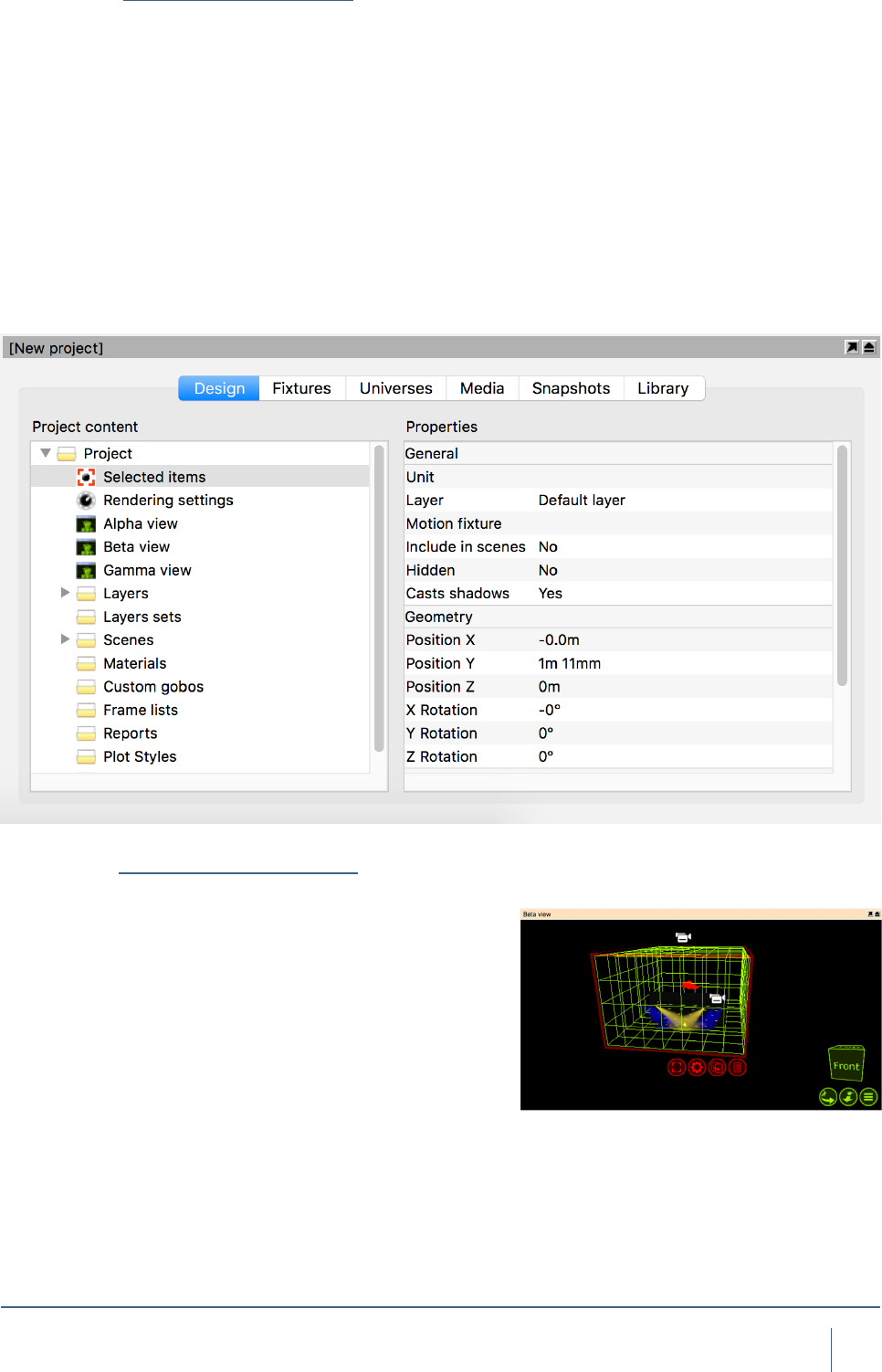
The Project Window
The Project Window is the main information area in Capture.
It hosts the properties for the selected items, additional set-
tings for the Alpha, Beta and Gamma Views, settings for
Layers and Layer sets, Scenes, Materials, Custom Gobo
wheels, Custom Frame (color) lists, Reports Plot styles and
Plots. Furthermore, the window is split into a navigation list
down the side with the properties for whatever is selected
from that list available on the right. Along the top are some
tabs - Design, Fixtures, Universes, Media, Snapshots and
Library. Generally speaking, to add an object of any type to
a capture project, it needs to be dragged from the library tab
to one of the simulator views. Objects can only currently be
dragged into a wireframe or plot view.
Atmosphere Settings
In Capture Atlas, Smoke is no longer a global setting, but
a placeable and modiable element of your design. Typical
applications include denser smoke on stage in an arena
with thin haze or other localized fog situations such as
heavy fog or fog behind a glass. Being able to limit smoke to
the area around the stage helps avoid problems with beams
shot into the audience over saturating the visualization. The
Atmosphere element is in a new project by default (much
like the camera object). Smoke can now also be patched
to DMX control. It has 2 control channels, Density (1) and
Variation (2). It can be patched by manually dragging the
object using the select button into your chosen universe
window (much like a xture) or manual given an address
once it is selected by changing its patch property in the
Design tab.
17
sofTware overvIew
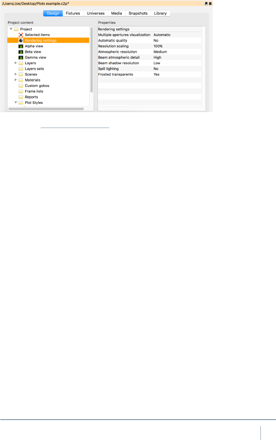
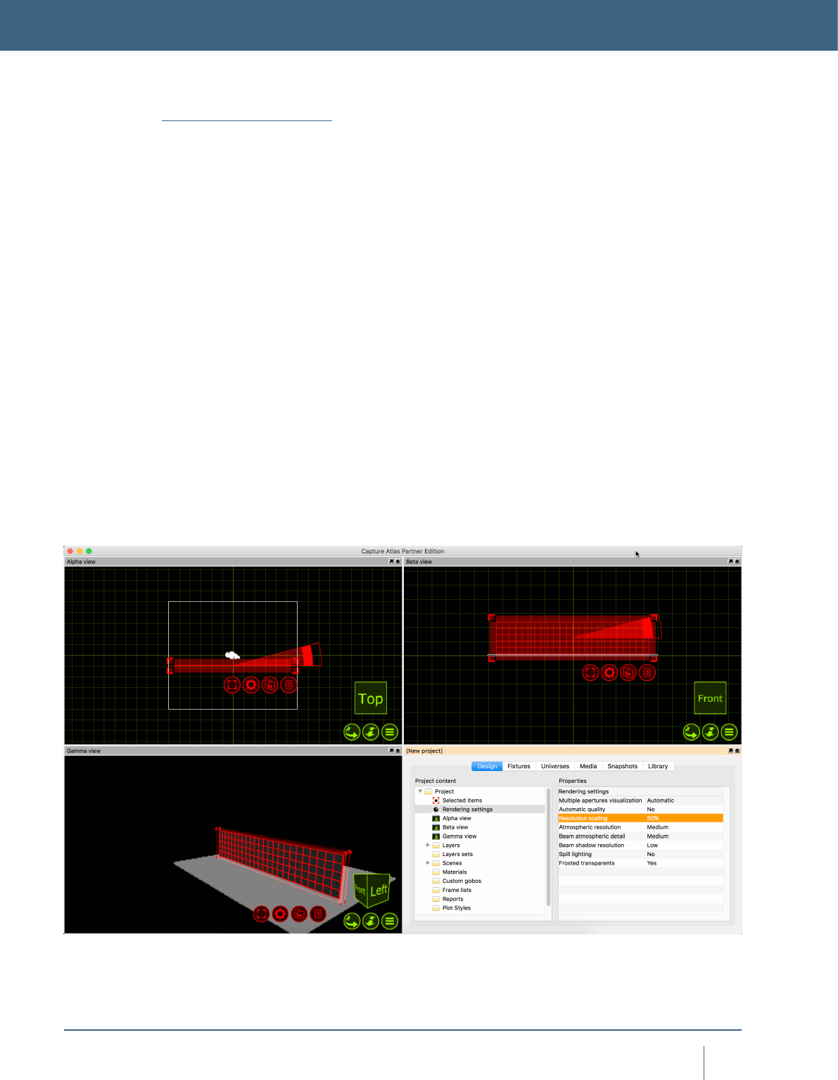
Rendering Settings
The rendering settings (previously visualization settings,
under software options) is a tab within the project window.
Its properties control the rendering quality of the live simu-
lator views.
The Multiple Apertures visualization option controls
the rendering of multi-aperture (striplights, BB-7, multi-LED
moving heads) beams. In simple mode, only a single beam
is rendered using the xtures average color.In realistic mode
each aperture renders a beam of its own. In Automatic mode
a single beam is rendered for the xture when all apertures
have the same color.
The Beam Atmospheric Detail option allows you to
control the level of detail created by a beam passing through
the smoke/haze in the atmosphere.
The Beam shadow resolution option allows you to lower
the resolution of shadows created by beams.
The Automatic Quality option allows you to turn on/off
the automatic quality functionality Capture uses. Having au-
tomatic quality turned on will allow capture to be more ef-
cient while rendering more complex scenes by sacricing
quality to keep good performance.
The Resolution Scaling option allows you to render live
visualization at a lower resolution than the screen.
The Atmospheric Resolution option controls the res-
olution of atmospheric visualization, (Smoke). The Beam
Atmospheric Details option allows you to control the level of
detail created by a beam passing through the smoke/haze in
the atmosphere. Higher levels of Beam Atmospheric Detail
are relevant when using many wide angle beams and/or
shooting through scenery that intersects beams.
The Beam Shadow Resolution option allows you to in-
crease the resolution of shadows created by beams when
shooting over long distances or on/through scenery.
The Spill Lighting option enables the visualization of a
beam contribution beyond a xtures eld angle.
The Frosted Transparents option allows you to disable
the visualization of the frosted effect of transparent materials.

OBJECT MANIPULATION
19
objeCT ManIpulaTIon
OBJECT MANIPULATION
Object Manipulation
Any physical thing in a Capture project le is an object,
whether it be a Lighting Fixture, piece of stage deck, LED
screen, table or chair - is irrelevant. They are all treated the
same in respect to adding them to the project, moving them
around, cloning (copying) them, deleting them and access-
ing their properties.
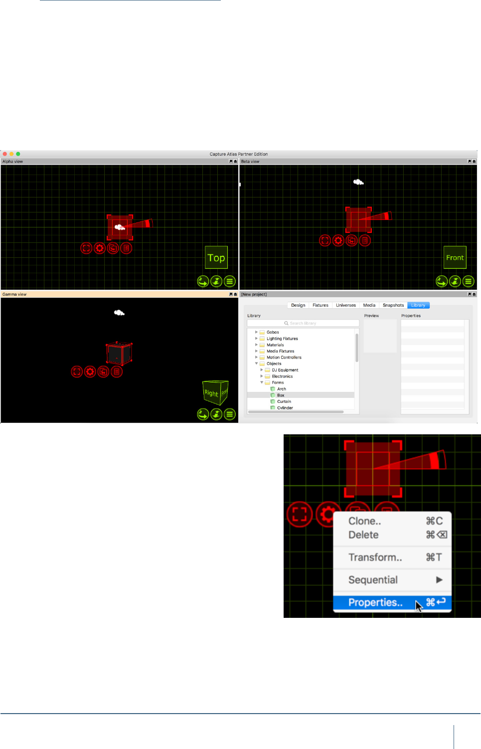
To explore more about object manipulation, start a new
Capture Project. Do this by going to the main menu in the
top left corner and pressing New.
Leave the Alpha and Beta views with their default set-
tings. Change the Gamma view to the Live mode by clicking
on the green list button and selecting Live. Your windows
should look the same as the image below.
20
objeCT ManIpulaTIon
Adding objects to the project
Now we have a clean project le, we can proceed to add
some objects to it.
To add an object to the project, we must rst locate it from
the Library. The Library tab in the Project Window is where
all objects can belocated. We want to add a stage oor.
Navigate to the Library, double click on Objects, then
again on Forms. Click on the Box form and drag it into either
the Alpha or Beta view. Your project should look something
like the image below.
We can now proceed to changing the properties of the box
so that it looks more like a stage oor. You may select the
box by simply clicking on it in any of the views. The red nav-
igator will appear around the box. Press the red spanner
button to present the options available for the box.
Click the Properties option. This will toggle the project
window to the Design tab with the Selected Items section
already active showing the properties for the box.
Change the box dimensions to a width of 12m, height of
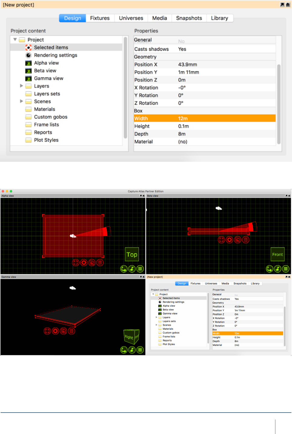
21
objeCT ManIpulaTIon
0.1m and a depth of 8m. Your Properties should look like
the image below.
The end result will be the box looking a lot more like a oor,
shown below.
Now we have a stage oor in place we can proceed to add
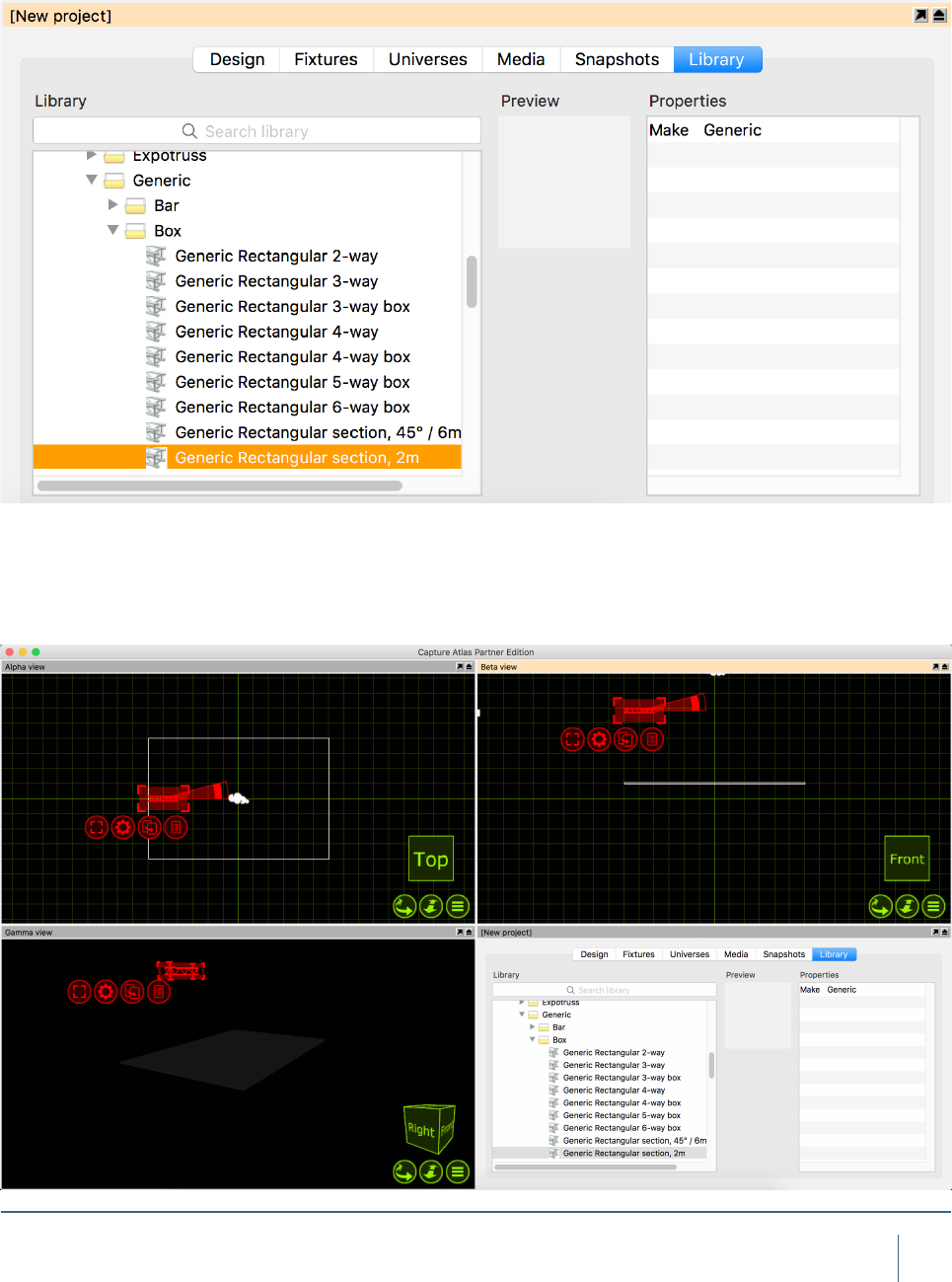
22
objeCT ManIpulaTIon
some more objects. We will add some truss in above the
stage. Adding a piece of truss is done in the same way the
box was added. Locate the desired piece in the library and
drag it into either the Alpha are Beta view. For the sake of
example, we will use a piece of truss from the Generic
folder. Double click the Truss folder, double click again on
the Generic folder, and again on Box. Choose the Generic
Rectangular Section and drag it into one of the views.
The Truss is 2m wide. We know that the stage oor is 12m
wide. We now want to add more 2m sections of truss to
result in one long truss going from one side of the stage to
the other. This can easily be done with the Clone feature.
Click on the truss piece to select it. Press the red spanner
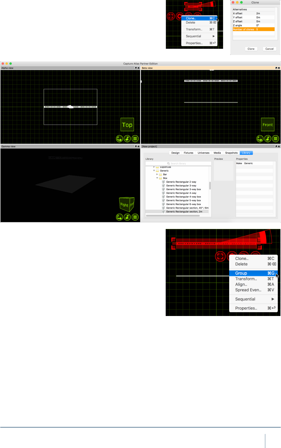
23
objeCT ManIpulaTIon
button to access the available options for the truss.
Click the Clone option, this will bring up the Clone window.
Set the X Offset to 2m and set the number of clones to 5.
This will then add sections of 2m truss right across our 12m
wide stage evenly.
Currently, they still act as 6 separate pieces of truss. Select
the pieces and press the red spanner button again. Choose
the Group option and now the 6 sections are grouped to-
gether. They can now be moved and manipulated all as one.

FIXTURES
25
fIxTures
Fixtures overwiev
Fixtures are handled in pretty much the same was as other
objects. To add a xture, it needs to be dragged from the
library to one of the wireframe simulator views. Fixtures can
be cloned, moved, rotated and deleted the same as any
other object.
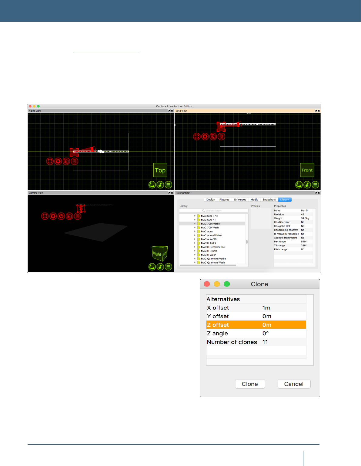
In this example, we add a single Mac 700 prole. We then
clone it we end up with one Mac 700 per meter of the truss
Clone the Mac 700 Prole 11 times so the 12m truss has
1 Mac 700 every meter. The Mac 700’s now span the truss
equally.
FIXTURES
26
fIxTures
Patching
Now that we have added the Mac 700’s. They need to be
patched. There are two ways of patching xtures in Capture.
You can select the xtures you wish to patch, in the order
you want them patched, and from the red spanner (options)
menu, you can select “Sequential Patch”. The sequential
patch window will appear giving you the options of “Start
Address”, which is formatted by double clicking the option
and entering Universe.Address. For examples entering 2.1
would patch the xtures to Universe 2, Address 1. You may
also enter a “Channels between xtures” number, this is es-
sentially an offset tool.
27
fIxTures
The second option is to drag the xtures to a start address
within a universe window. First, open one of the project uni-
verses by double clicking on it in the “Universes” tab of the
Project Window. Then select the xtures in the order you
wish to patch them, click and hold the drag button and drag
them to a start address in the open universe window.
28
fIxTures
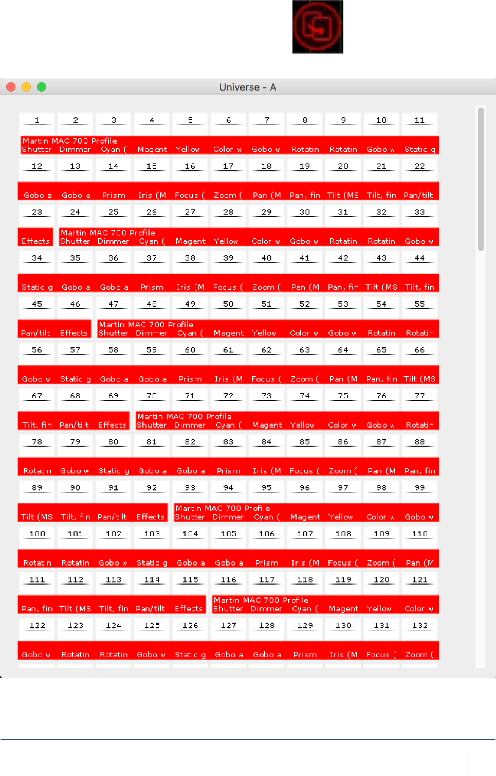
DMX Universes
Once xtures are patched onto Captures internal universes,
you can link those internal universes to external univers-
es that are coming into Capture via external protocols such
as Art-Net, sACN (E1.31), MA-Net (Windows version only),
Compulite VC’s, ETC Net 2/3, Hog 3/4 and LAN Box.
Very little user intervention is required with most of these
protocols. Capture will accept most of them in a “Plug &
Play” kind of manner. Once a universe is showing in the
“External Universes” section of the Universes tab, then it
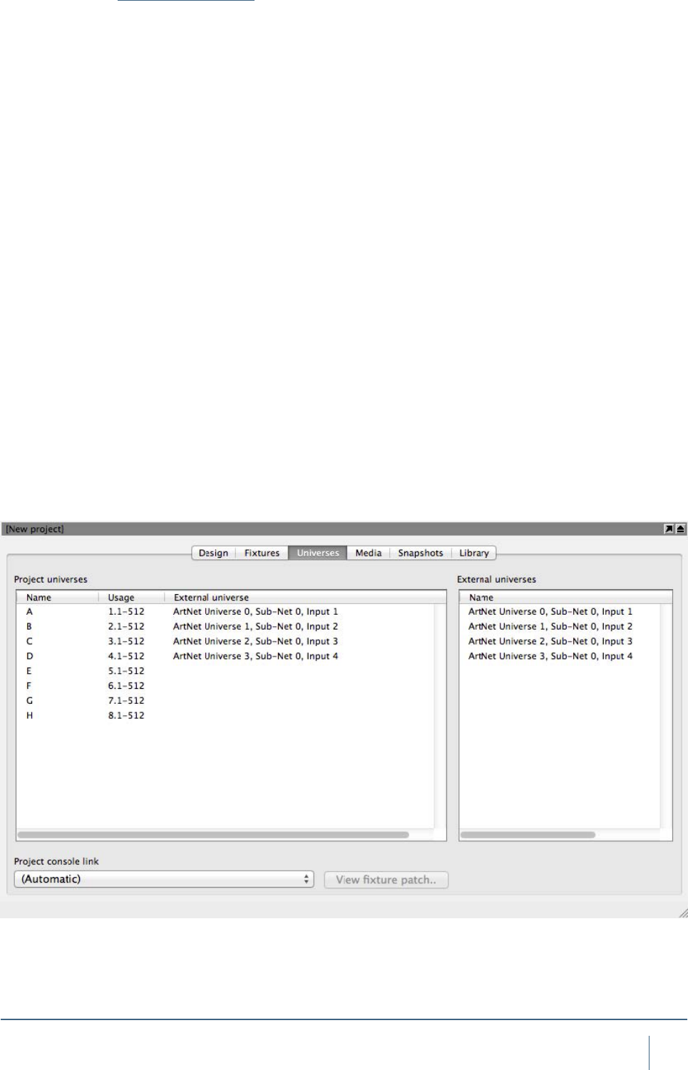
can be linked to an internal universe in one of two ways.
Universes are managed in the Universes tab of the Project
window. The left hand side shows the universes of your
project and the right hand side shows universes available
from lighting controllers. Capture attempts to automatically
connect these, but if you are working with multiple control-
lers you may wish to override this automatic setup. To do
this, select a project universe and then double click on the
right hand side on an external universe to pair it with.
By doing this, you will also set the “Block automatic con-
nection” property of the project universe.
Project universes are by default set up as independent
1-512 channel universes. The Usage column illustrates how
xtures patched to each universe will illustrate their patch. In
a theatrical environment it may be more convenient to work
with a consecutive range of channel numbers (for instance
1 – 2048). This can be achieved by setting the Patch base
property of the universes to match your console setup
29
fIxTures
Fixture Settings
Changing the settings of Fixtures in the Project is done
in the Design Tab of the Project Window.Some of the main
xture properties that appear here:
Swapping Fixtures
Swapping xtures in Capture is very easy. To swap x-
tures, select the old xtures rst, then locate your new xture
from the library. Simply drag the new xture onto one of the
selected “old” xtures. The selection will go a purple color,
once you see the purple color, release the mouse button
and the xtures will have been swapped.
30
fIxTures
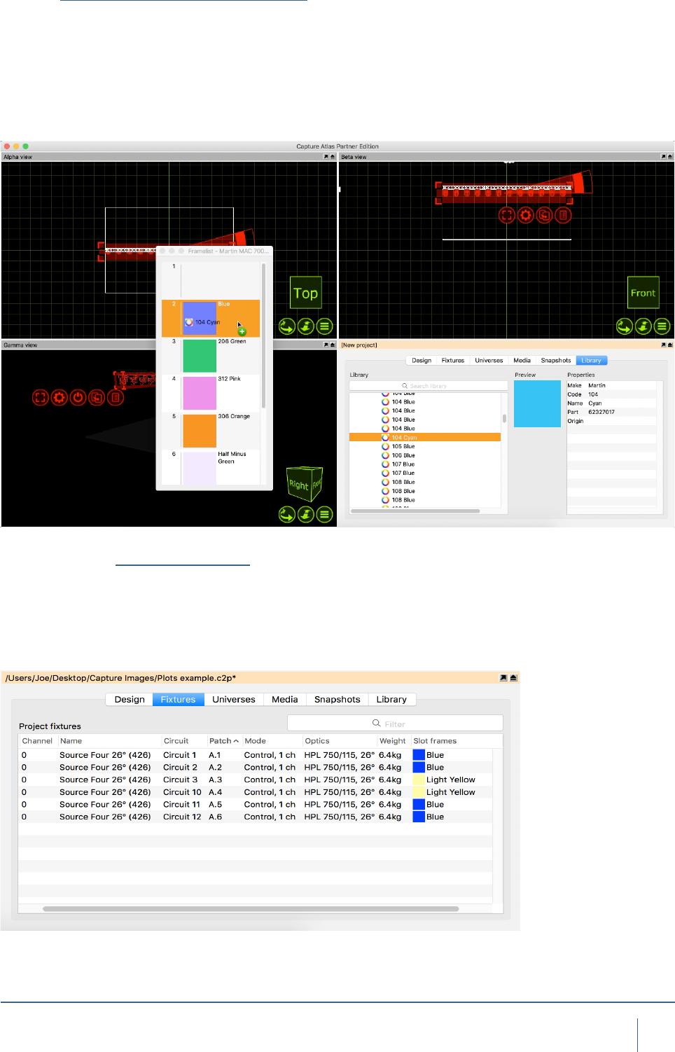
Custom Gobo/Color Wheels
Changing Gobo/Color frames in intelligent xtures is very
easy, simply open the current wheel via the xture proper-
ties, double clicking on one of the current color/gobo slots
in the properties opens the wheel, then drag a new color or
gobo from the library to a slot on the wheel and the xture is
automatically updated.
The Fixture Tab
The Fixture Tab is part of the Project Window. It shows all
Fixtures in the show, and all of the following information for
them: Unit Number, Channel Number, Name, Circuit, Patch,
Mode, Optics, Weight, Color Frames.
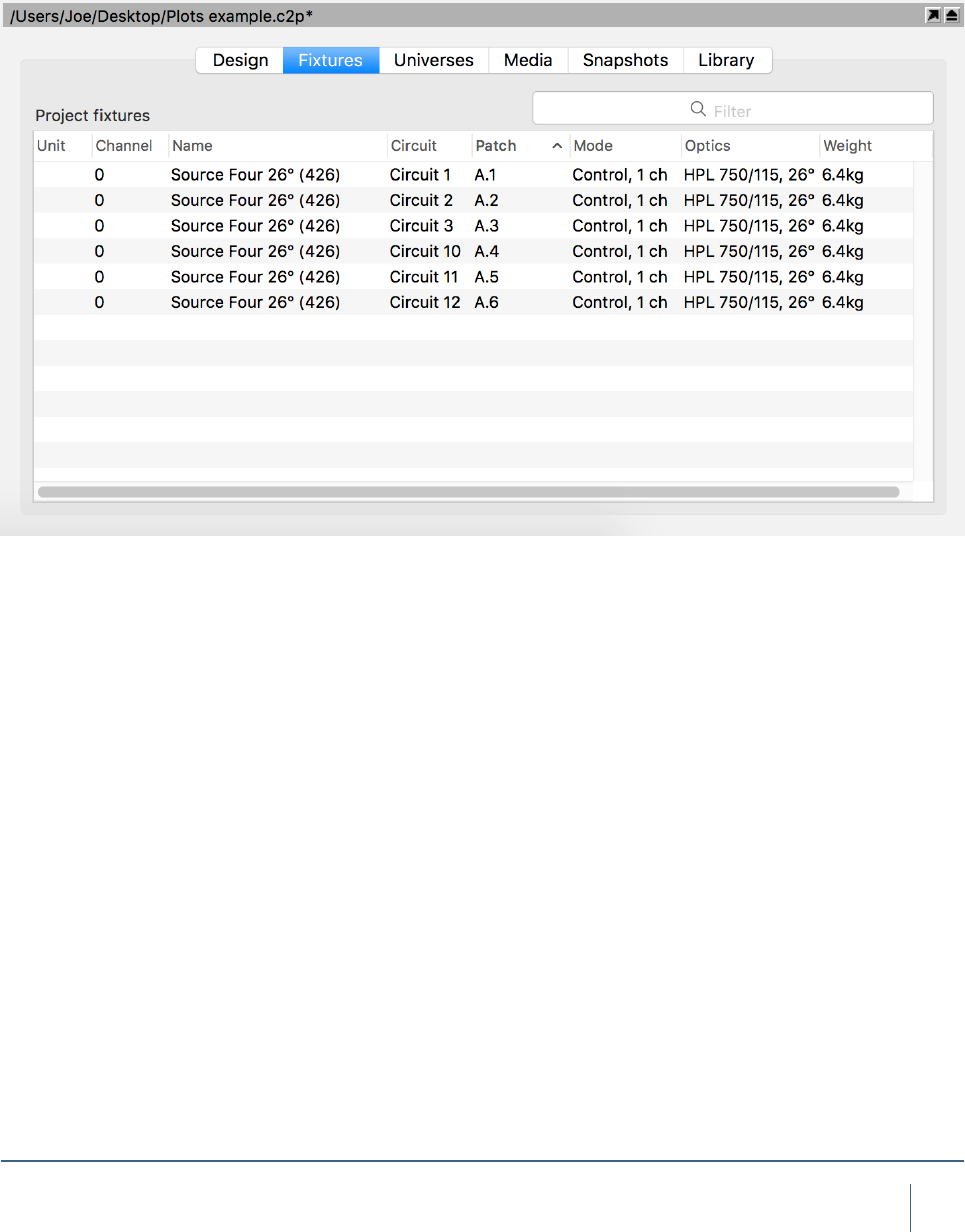
31
fIxTures
The Fixture Tab can be arranged in a number of ways.
By default, the tab shows all xtures currently in the
project. It can be ltered by using the search function in the
top right corner. It can also be ltered by clicking a column
header to organize the data in ascending (or descending)
order for that property. For example, in the image below, the
window is ltered to show the source four xtures ascend-
ing in patch data. The arrow in the Patch property column
header denotes that the sheet is arranged showing patch
data in ascending order. Clicking the Patch column header
for a second time would toggle it into descending order.

MATERIALS
33
MaTerIals
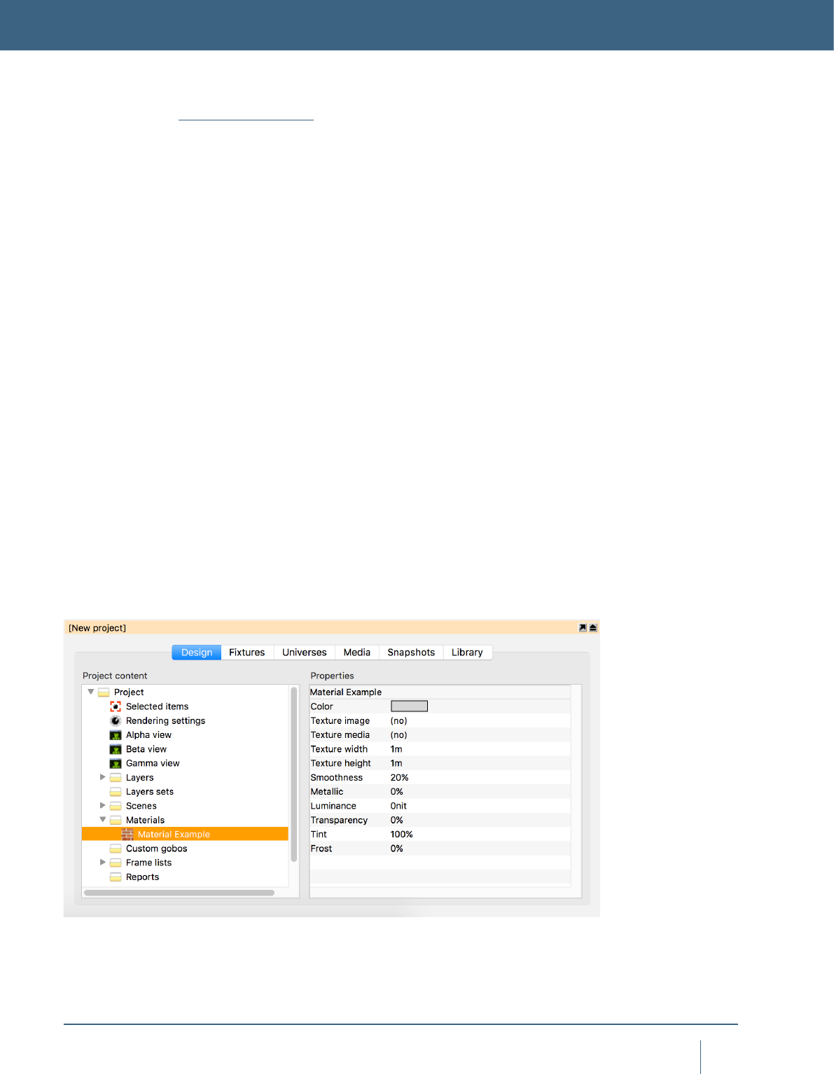
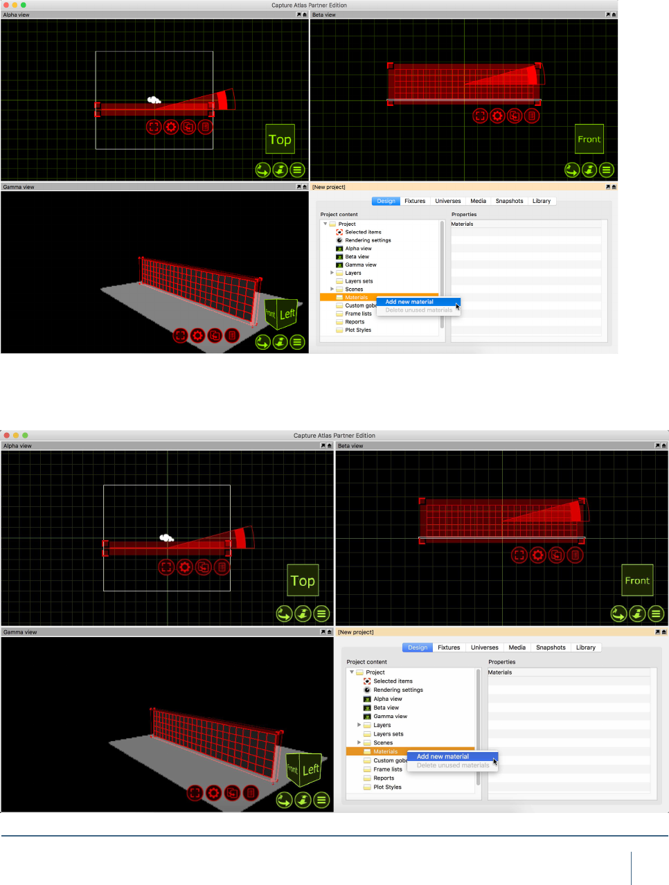
Using Materials
Materials offer a way of applying a static image or video
to an object. The best way to use a material is to think of it
as an example of what you object is going to look like. They
are useful to make objects appear as different things, for
example mapping a picture of a bricks to a thin box, making
it appear as a wall.
The library contains a selection of materials which can be
applied to objects by dragging and dropping them from the
library on to the object. To apply the same material to many
objects, you can select the objects rst and then drag and
drop the material. The image and colour of the material is
combined with the colour of the object that the material is
applied to. Hence, if the object’s colour is set to black, the
material will appear black.
You can create your own materials in the Design tab of the
Project window by right clicking on the Materials branch.
You can then apply either an image from a le, a video on
the local hard drive or streaming video source from a con-
nected media server. To apply your own materials to objects,
drag and drop them from the Materials branch rather than
the Library tab. The Self illuminated property allows you to
create materials that simulate light emitting surfaces such
as at screens or LED panels.
Use the Width and Height properties to dene the physi-
cal real-world dimensions of the image or streaming video
applied. These dimensions dene the size of the image re-
gardless of the object it is applied to.
MATERIALS
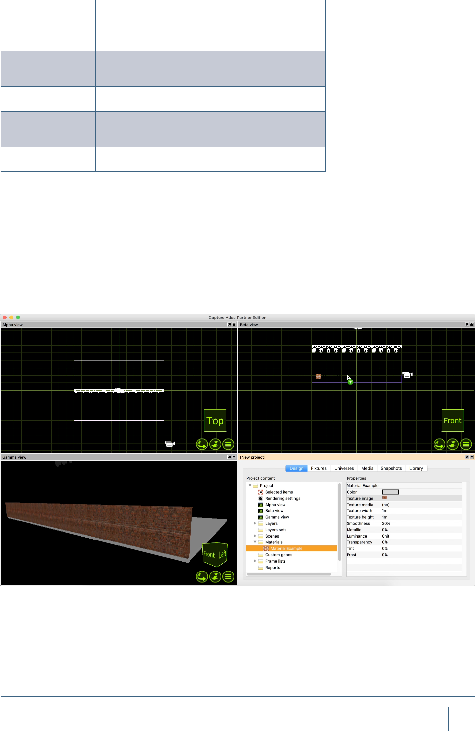
In this example, we will look at using Materials to change
the appearance of a thin box. First, make a new material in
the project window. You may name your material by right
clicking on it and choosing “Rename”.
34
MaTerIals
New to Capture Atlas are the following image options
Smoothness
The Smoothness property dees how rough or smooth
a surface is on a microscopic level. A material such as
concrete would have a much lower smoothness value
to say, varnished wood.
Metallic
The metallic property allows you to mimic metallic
looking nishes for metal items such as a car or steel
beam.
Transparency Transparency allows you to set transparency for an
object to act like a piece of glass.
Tint
Tint allows you to tint the color of an object, and when
done in conjunction with transparency, can create a
stained glass style effect.
Frost Frost allows you to apply a linear frost value to an
object.
In the material properties, available on the right when the
material is selected, you may choose an image or video
source. Double click on
the image option and choose an image from the local
hard drive. In this instance, the image will be a picture of
some bricks. Once you have
chosen the image, drag the material from the project
window to the object you wish to map it to.
35
MaTerIals
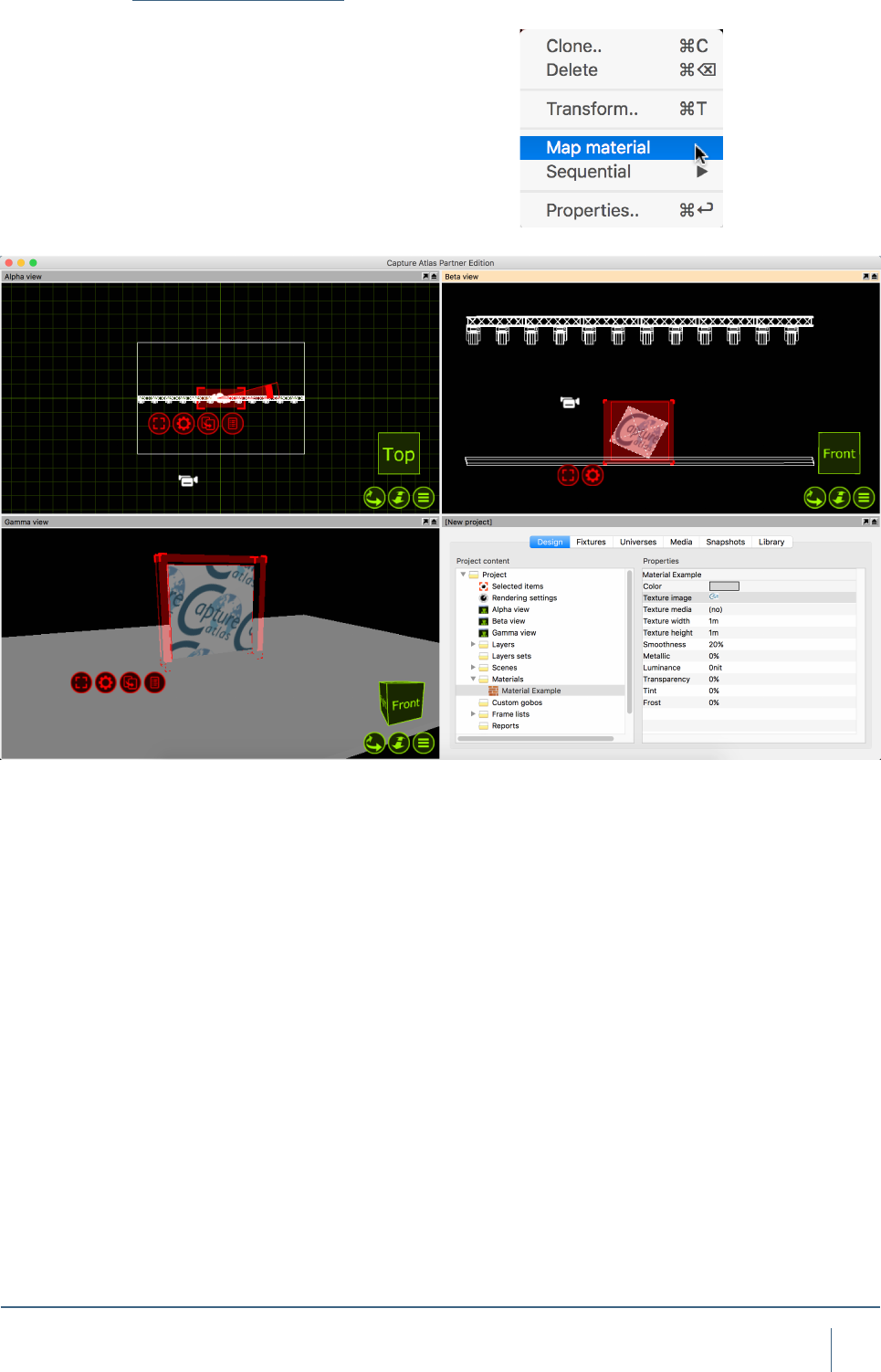
Mapping Materials
Once you have applied a material to an object, you may
wish to map the material. Mapping a material consists of
using the navigator to resize it, rotate it or ll the object
space with the material, the latter is referred to as “Map to
Extents”. Moving and resizing the material with the naviga-
tor is done in the same manner as other objects. You may
Map a material to multiple objects at the same time. Simply
select all to the objects and drag the material to them, select
the “Map Material” mode and map the material to your liking.

MEDIA FIXTURES
37
MedIa fIxTures
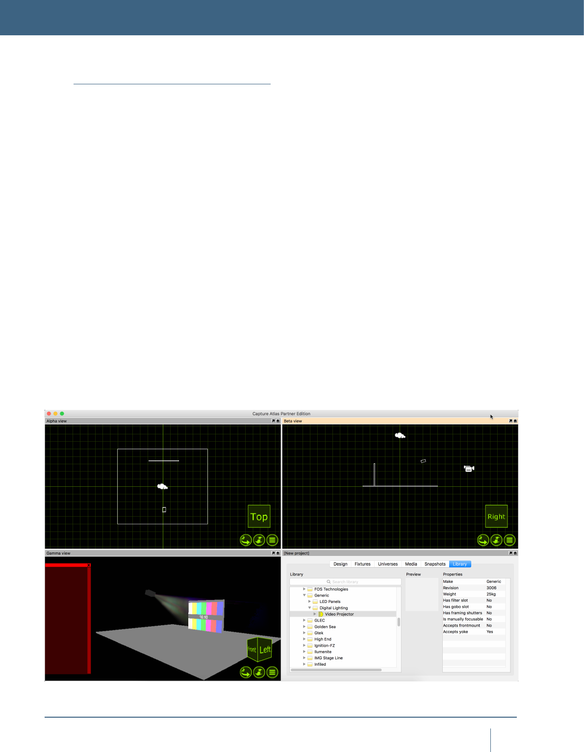
Video Projectors & Digital Lights
Capture now supports a large library of Media Fixtures
such as Video Projectors and Digital Lights. Adding a Media
Fixture to a Capture Project is the same as anything else -
drag it from the library into one of wireframe views.
With Projectors and Digital Lights, they need a video
source for any output to be visible. Much like LED Screens,
the video source may be an internal video player were by
you choose a video le on the computer and play that.
Alternatively you may also choose a video source from an
external Media Server via CITP for the video source of a
Projector.
In this instance we will just use a le on the computer and
look at CITP sources in a later chapter.
Add a video projector to the project by dragging it from
the library to one of the wireframe simulator views. You can
select a non specic projector from the “Generic” section
of Media Fixtures in the library. Add a box, and change its
properties so that it looks like a video screen. Position the
projector so it is pointing at the screen. A quick way to focus
a projector (or any type of xture) is to right click on the
surface you wish to focus it on. In this case, its the screen
on stage.
The projector will display a test image when it is turned on
but not being assigned an image or media player.
MEDIA FIXTURES
38
MedIa fIxTures
Now, to play video from the projector, you must make a
video player within capture. Simply, go to the Media tab in
the project window and press the “Add” button in the top right
corner and name the Video Player - “Projector Video”. Press
the “Add Video” button and choose a video le from the local
hard drive. You may select multiple videos if you wish. Once
you have selected the video you wish to play through the pro-
jector, press the play button next to it so the video is playing.
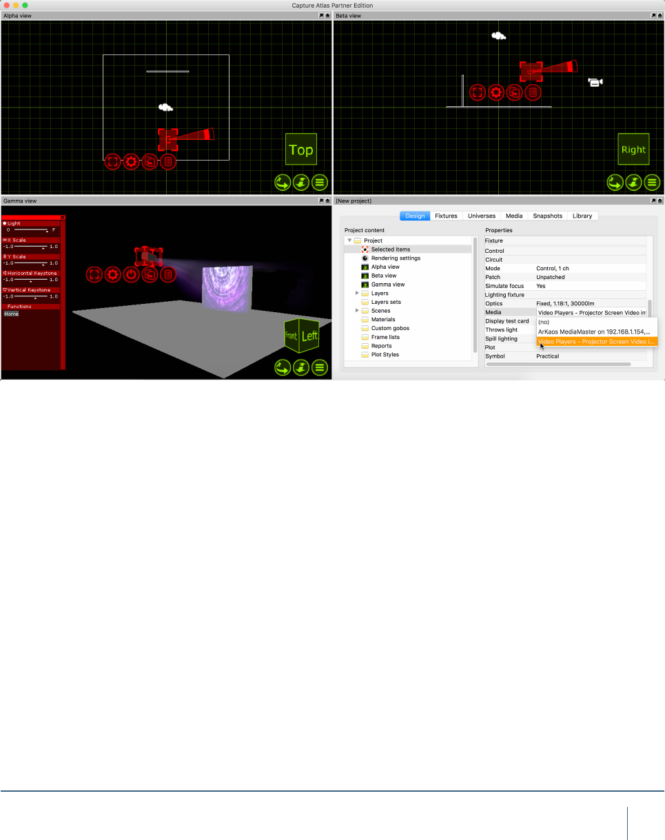
Select the Video Projector and access its properties. In the
Project Window, double click on the “Media” Property of the
projector and choose the video player you made.
39
MedIa fIxTures
CHANNEL 1 CONTROL CHANNEL 2 PLAYLIST INDEX
0-7 Pause 0-31 Playlist entry 1
8-15 Play 32 DMX Values per entry
16-23 Replay (plays from the start) 248-255 Playlist Entry 8
24-31 Stop
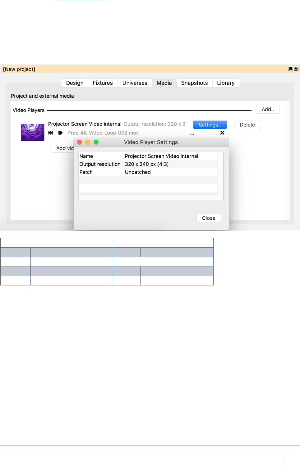
Video Players
As discussed in the previous section, you can use an in-
ternal Video Player to play videos or images on Video
Projectors in Capture. The Video Player can be controlled
by DMX if desired. The Patch property of the Video Player
can be access by clicking “Settings..” for the desired Video
Player in the Media tab.
40
MedIa fIxTures
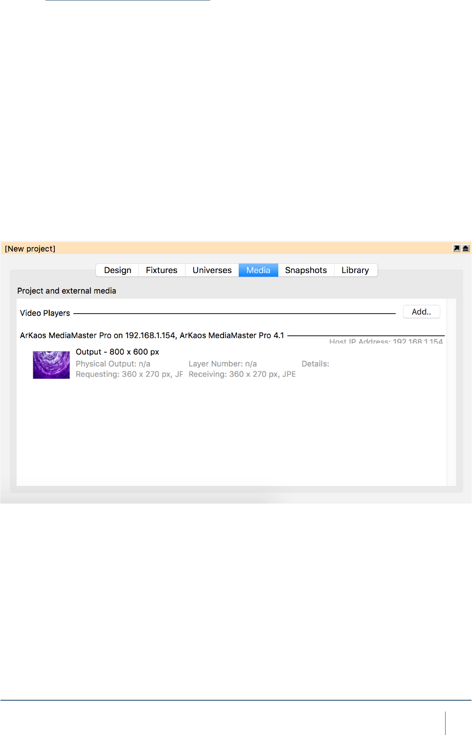
Using CITP Media Sources
Capture supports connecting to Media Servers using the
CITP communication protocol. This makes it possible to
receive streaming video from a Media Server and apply it
to objects like a material. You can view all connected Media
Servers in the Video tab in the Project window.
To apply a streaming video to an object, you must rst
create a material, select the desired video source, set up
the dimensions of the material and then apply the materi-
al to the objects. Alternatively you may omit setting up the
material dimensions and simply map the material using the
material mapping functionality discussed earlier.
Little to zero conguration should be required with CITP.
Ensure that the Capture machine and the Media Server are
operating in the same range of IP addresses and subnet.
If the Capture machine has multiple network adapters, it
may be necessary to manually select the adapter you will
be using for CITP information. This can be done in the
Connectivity Tab of the Options menu.

41
MedIa fIxTures
Controller & Media Server Connectivity
NDI Video Sources
Capture supports receiving video from NewTek NDI (http://
www.newtek.com/ndi.html) video sources. This makes
it possible to receive streaming video from a multitude of
both software and hardware solutions. There are also some
useful tools for desktop streaming and tests available from
the NDI web page of NewTek. Capture lists all NDI sources
it nds in the Video tab in the Project Window.
To apply streaming video to an object, follow the same
procedure as with CITP Media Sources, described in the
previous section.
No conguration is required for NDI, but it is possible to
specify one or several NDI groups to limit NDI reception to
in the Connectivity Tab of the Options menu. If the Capture
machine has multiple network adapters, it may also be nec-
essary to manually select the adapter you wish to use.
MAC OSX WINDOWS
Art-Net Ye s Ye s
Avolites ACDI Ye s
CITP Ye s Ye s
Compulite VC Ye s Ye s
EntTec DMX USB Pro Mk1 & Mk2 Ye s Ye s
ETC Net 2 Ye s Ye s
Green Hippo HMap 3 Ye s Ye s
Hog 3 & 4 Ye s Ye s
Kinesys K2 Ye s Ye s
LaserAnimation & Pangolin Ye s Ye s
MA Net 1 & 2, version 2.9+* Ye s
Streaming ACN Ye s Ye s
*Requires manual activation; right click in the External universes list of the Universes tab to
open the MA-Net conguration dialog.

LED SCREENS
43
led sCreens
Using LED Screens
Capture is not only capable of 3D rendering for Lighting
Fixtures, but also a wide range of LED Screens too.
Adding an LED screen to a project, is the same as adding
a xture or object. LED Screens can be found under the
Media Fixtures section of the library. Locate the particular
model you require from the library and drag it into one of the
wireframe simulator views. Use the clone function to clone
the LED panel however many times is required to create the
screen size you desire. Once You have added in an LED
screen of the desired size. Mapping video to the screen is
done with the use of Materials and Video Players.
Materials are images or videos you add to an object in
capture. Video Players can either be an internal video player
were by you choose a video le on the computer and play
that. Or you may also choose a video source from an exter-
nal Media Server via CITP for the video source of a material.
In this instance we will just use a le on the computer and
look at CITP sources in a later chapter.
Add an LED Panel to the project by dragging it from the
library to one of the wireframe simulator views. Clone the
panel so you have a suitable size of LED Screen. Your
project should look similar to this.
LED SCREENS
44
led sCreens
Now, to play video on the LED Screen, you must make a
video player within capture. Simply, go to the Media tab in
the project window and press the “Add” button in the top right
corner and name the Video Player - “LED Screen Video”.
Press the “Add Video” button and choose a video le from the
local hard drive. You may select multiple videos if you wish.
Once you have selected the video you wish to play on the
screen, press the play button next to it so the video is playing.
In the project window, right click on the Materials node and
press “Add new Material”.
Once you have created the material, you need to link the
material to the video player. Do this by selecting the video
player from the “Media” option within the material properties.
45
led sCreens
Once the Material has been assigned to the video player,
drag the material from the project window to the LED Screen
in one of the simulator views. Press the red spanner button
and choose the “Map Material” option. Then select the “Map
to extents” option, this will set the material to ll the whole
screen.
The result will be the LED Screen receiving evenly mapped
video across the array from the Video Player.

LAYERS & LAYER SETS

47
layers & layer seTs
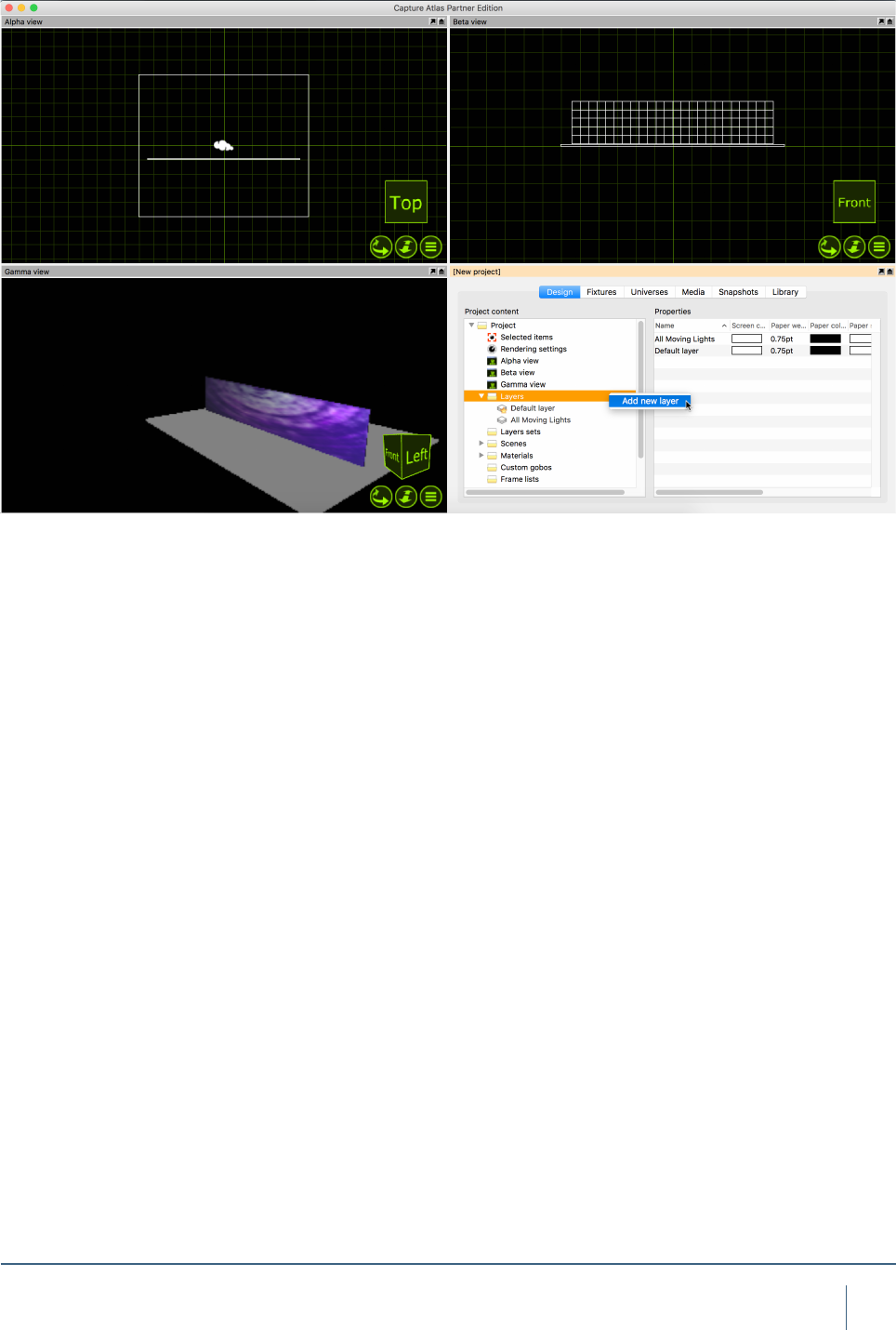
Using Layers
Both layers and layer sets are managed in the Design tab
of the Project window. They are created by right clicking on
their corresponding branch on the left hand side. Layers are
useful to select & group many objects of a similar nature.
Layer sets are essentially just groups of layers. For example
having a layer for “All Moving Lights”, “All Generics” and “All
LED” could be useful. Then they could belong to the layer
set - “All Fixtures”. Layers and Layer Sets are very useful
for managing project les with large amounts of objects &
xtures in.
Objects in a layer with the Locked property set cannot
be modied. When the Include in reports property is un-
checked, objects in that layer will not appear on reports. Live
information and Fixture simulation can also be turned on
and off on a per-layer basis in the same fashion. Layer sets
are used to dene sets of layers to be visible in simulator
views and plots. They serve as layer lters and it is useful
to note that you may work with different layer set in different
views if you wish.
When a simulator view is patched to a universe it is pos-
sible to choose the simulator view’s layer set via DMX.
However, this requires setting up the DMX control slot
property of each layer that you wish to be able to choose.
There are 64 slots available and they are identied with the
numbers 1 through 64. A value of 0 means that it is not pos-
sible to select via DMX.
Please note, that hiding layers does not affect light and
shows because the objects are still considered physically
present. So in order to achieve something like this, you must
use Scenes.
LAYERS & LAYER SETS
48
layers & layer seTs
To make a new layer, simply right click on the layer node
in the project window and press “Add new layer”. Name the
layer at this point too.
Adding xtures or objects to the layer can be done in
one of two ways, you may either drag the layer from
the project window to the selected objects or you may
select the objects and double click the “Layer” prop-
erty in the properties and select the layer there.
Adding xtures to an existing layer is done in the same
manner.
49
layers & layer seTs
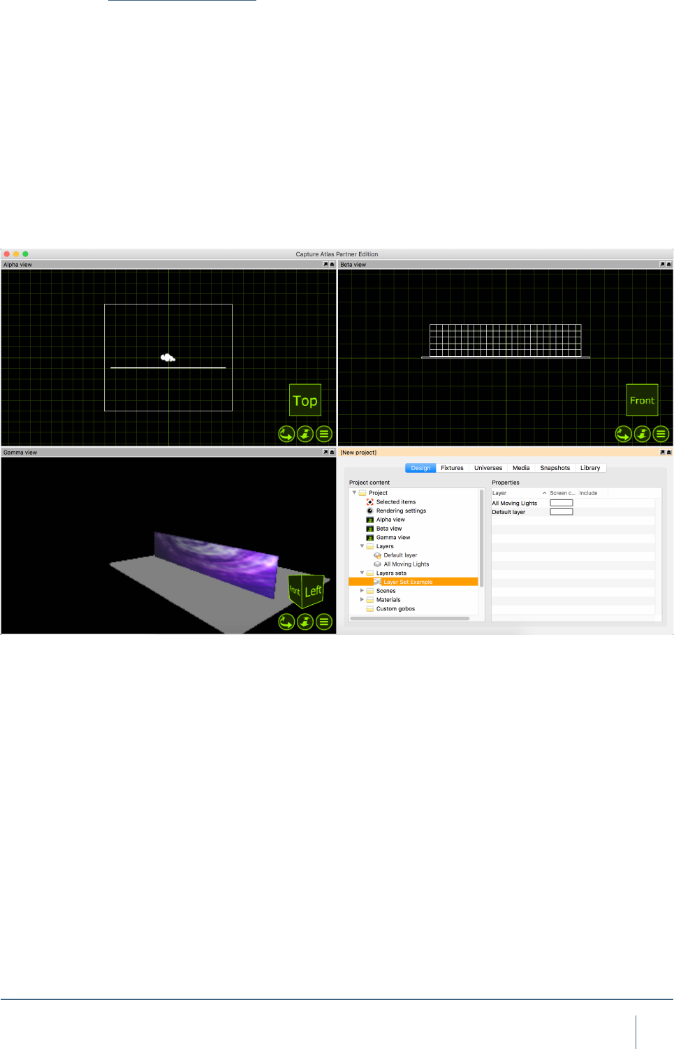
Using Layer Sets
As already discussed, Layer Sets are essentially just groups
of Layers. As per our previous example, having a layer for
“All Moving Lights”, “All Generics” and “All LED” could be
useful. They could then belong to the layer set - “All Fixtures”.
Adding Layer Sets is done in the same was as layers.
Right click on the layer set node in the project window and
select “Add new Layer Set”. Name the layer set accordingly.
Once the layer set is made, select it, by clicking on it. In the
right hand section of the window, a listwill appear showing
all the current layers. You can use the check boxes to control
which layers belong to the layer set you created.

SCENES
51
sCenes
Using Scenes
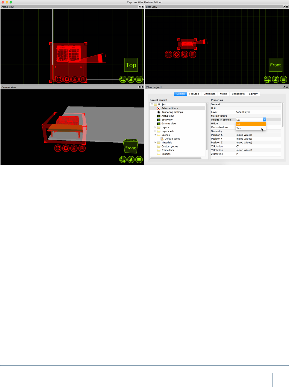
Working with scenes allows you to modify the position
and visibility of objects in different parts of a performance.
If you wish to do this, it is important to set the Include in
scenes property of the objects that wish to have dynamic
positioning/visibility (this is important because many items
such as the rig, truss and house will usually not be part
of what can be moved during a show and keeping them
out of scenes prevents you from making serious mistakes).
Scenes are not stored or recalled – you are always
working in one scene at a time and you can safely switch
back and forth between scenes without risking loss of
any position information. Scenes are most useful in a
Theatre environment were you have one set of scenery
for Act one and another set of scenery for Act two.
By default there is already one scene in any project le - the
“Default Scene”. To make more Scenes, right click on the
scene node in the project window. Select “Add Scene” and
name the scene accordingly.
SCENES
52
sCenes
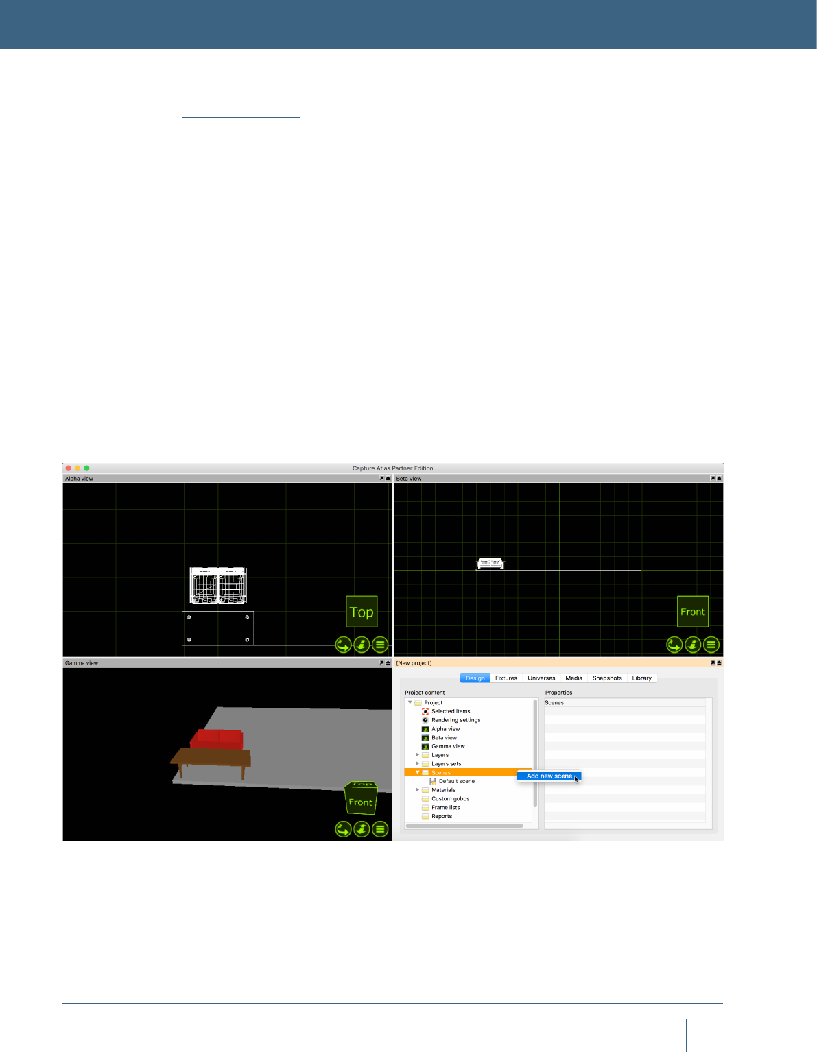
Once you have made a second scene, we can proceed to
make a scenery change. Add some scenery and position
it as per your liking. Select all of the scenery, in the prop-
erties, locate the “Include in scenes” property and set it to
“Yes”. Now double click your second scene (or right click
on it and select “Go to scene”). Now we are in the second
scene, move the scenery to a new location. Now switching
between the two scenes moves the scenery between the
two locations.

PLOTS & PAPERWORK
54
ploTs & paperwork
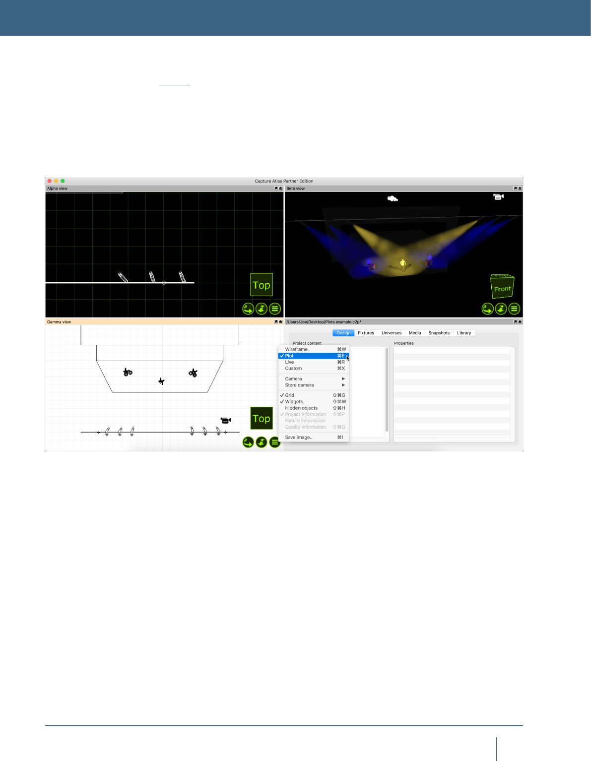
Plots
The plots functionality in Capture allows users to create pa-
perwork of lighting plots featuring key information about the
lighting rig. A plot can be viewed and edited in any simulator
view that is orientated to the top view & plot mode, as shown
below.
PLOTS & PAPERWORK
55
ploTs & paperwork
Plot Options
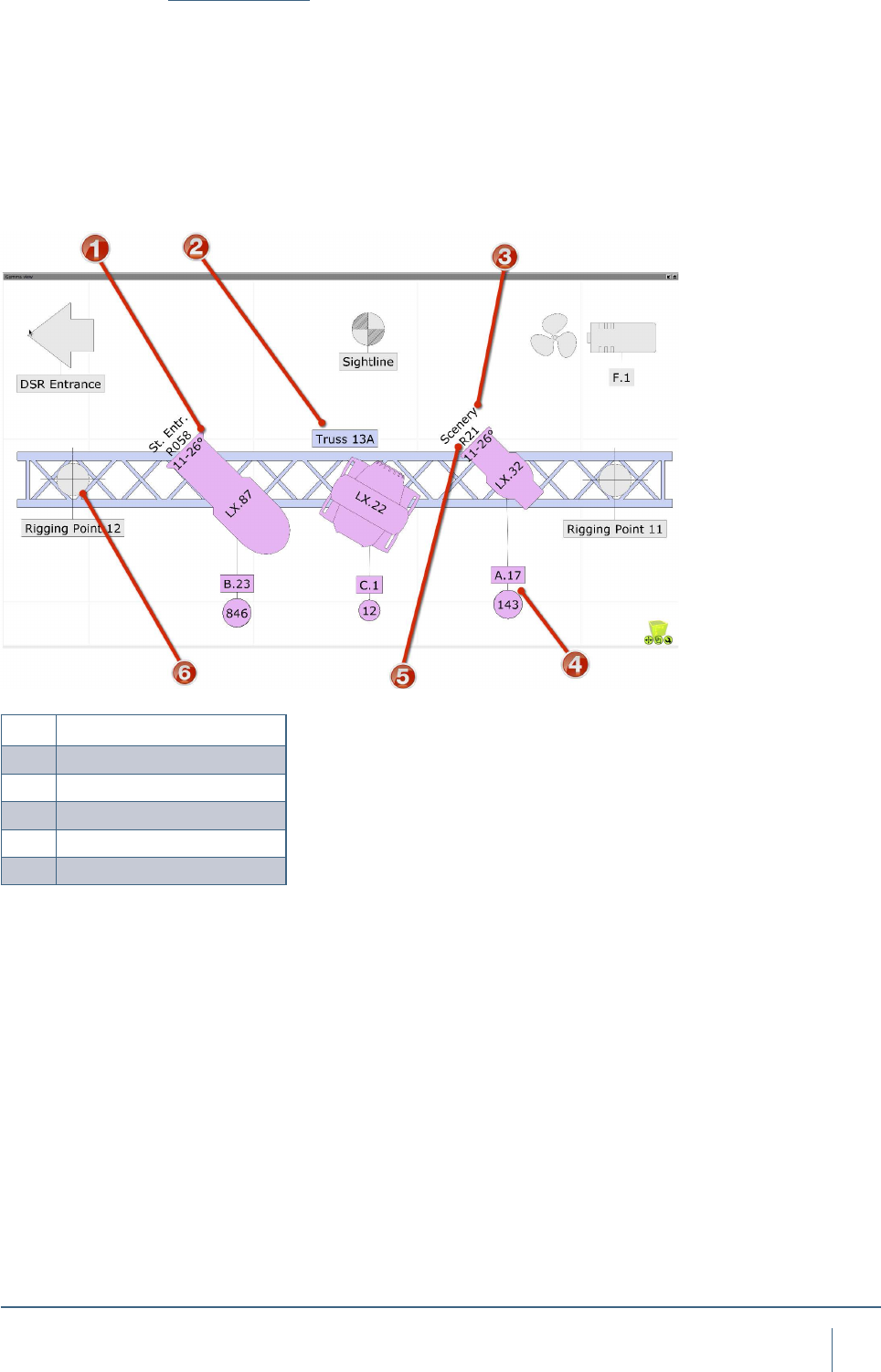
Other than Fixture symbols, there are many other symbols
that can appear on plots. The interactive image below
shows examples of the available plot symbols. Symbols
such as Sightlines, Fans, Fog Machines, Rigging Points etc
may all be dragged into the project from the library just like
other items. If you are unhappy with the default symbol for
a xture, you may drag a different symbol from the library to
the selected xture.
1Optical information
2Label
3Focus Information
4Patch & Circuit Information
5Colour Filter Information
6Rigging Point
56
ploTs & paperwork
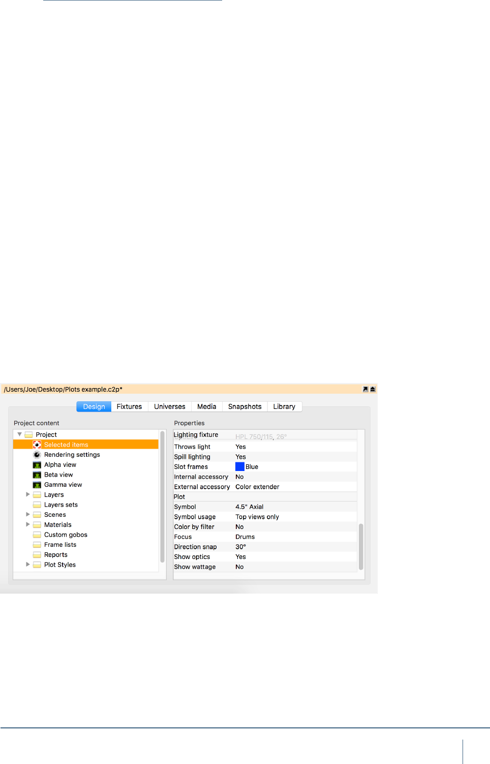
Fixture Properties with Plots
When xtures are selected, there are some plot specic
properties that are useful to know about.
“Symbol” will control which symbol is used on the plot for
the selected xture.
“Symbol Usage” will control which views the symbol actu-
ally appears in.
“Direction snap” is set to 30 degrees by default, this prop-
erty controls the direction the xture is facing on the plot.
“Color by ler” will set the xture color to match the gel
lter it has.
“Focus” is the property that allows text to be placed in front
of the xture to indicate where that xture is focused. Ie,
drums.
“Show Optics” is the property that controls whether or not
the plot displays the optical information of the xture.
“Show Wattage” is the property that controls whether or not
the plot displays the wattage information of the xture.
57
ploTs & paperwork
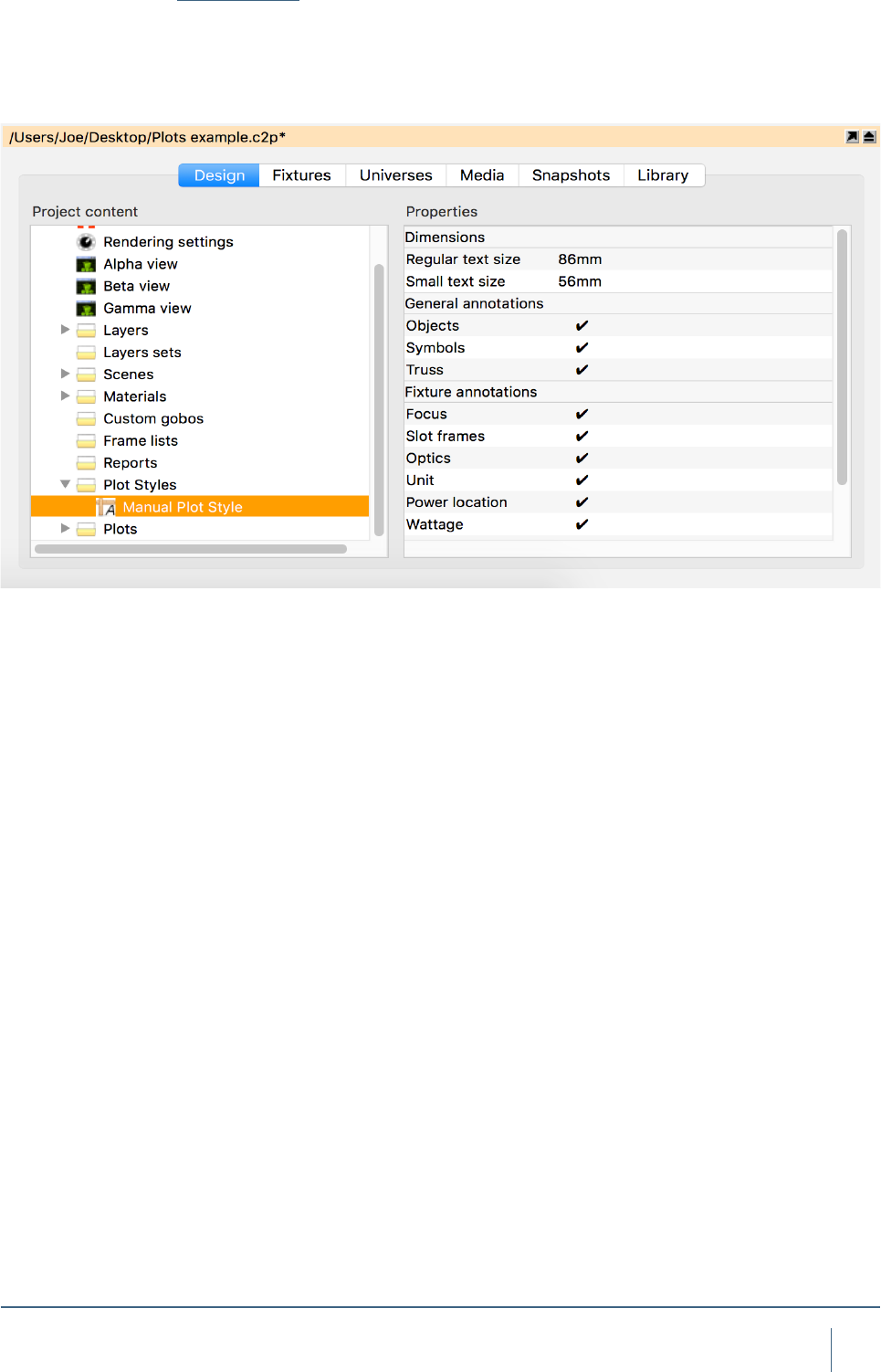
Plot Styles
With Capture Argo, there is now an option to create styles
for use with specic plots later. There are multiple properties
that can be included in a style, which can toggle on and off.
58
ploTs & paperwork
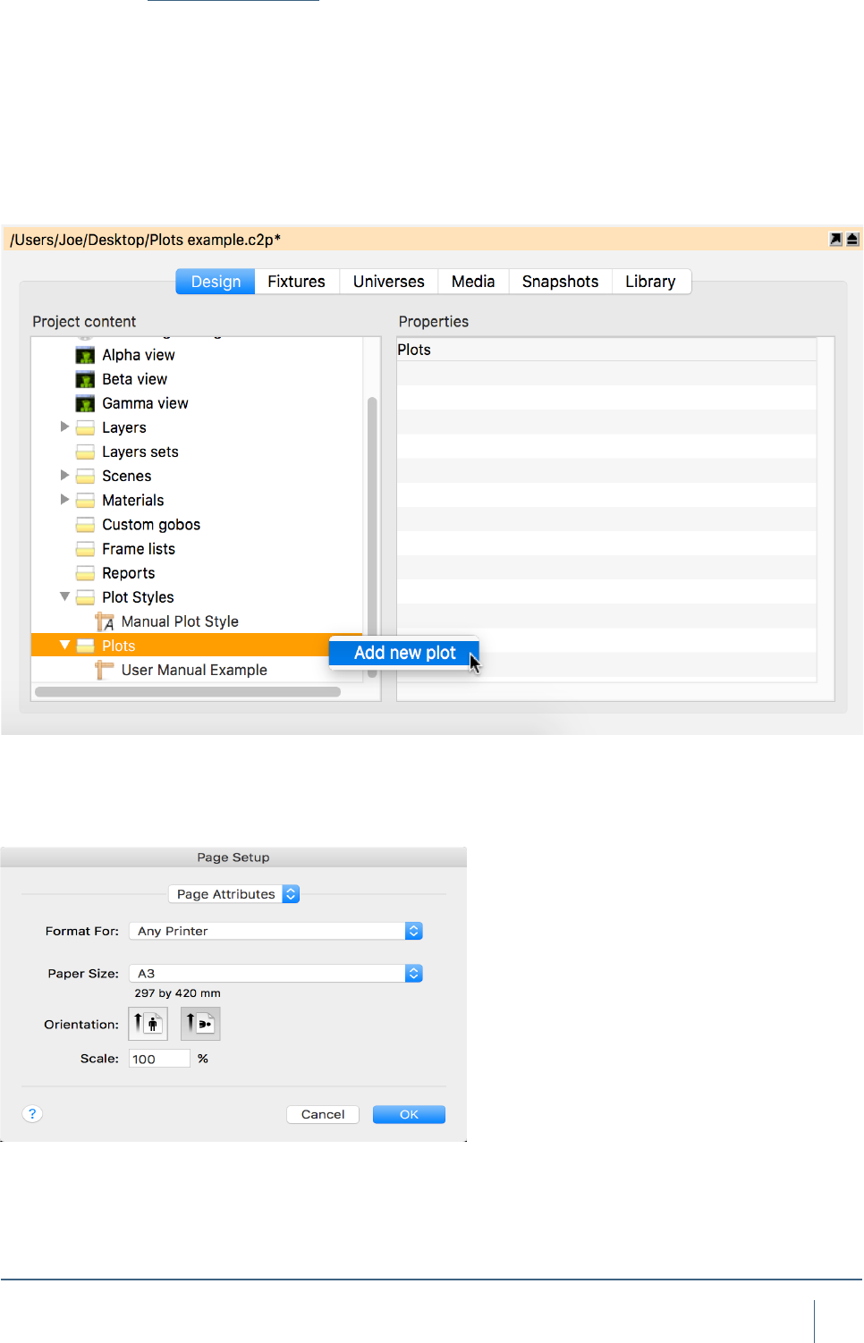
Exporting Plots
Once a plot has been made in a paper simulator view, it can
then be exported for print. To do this, create a new Plot by
right clicking on “Plots” in the Project Window and clicking
“New”. Multiple Plots can be added in this manner. Adding
multiple plots to the same project le is very useful for creat-
ing tidy plots for only certain parts of a rig. Each Plot can be
setup to show only certain Layer sets and Layers based on
the view you insert into it.
Once you have added a plot in the Project Window. Double
click on it to open it. The paper settings can be changed in
“Page Setup”.
59
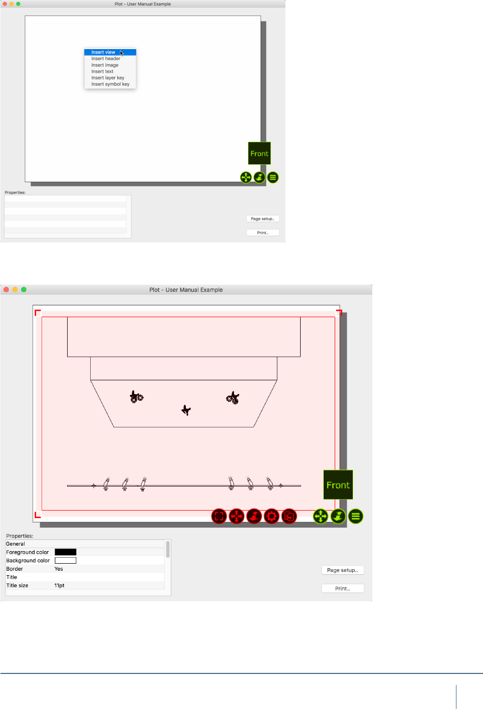
ploTs & paperwork
Right clicking on the plot will allow you to add a view to
the plot as shown in the image below. You may also add
Headers, Images, Text, Layer Keys and Symbol Keys in the
same manner as adding a view.
Scale and move the plot to suit the paper.

MODEL IMPORT

61
daTa IMporT and exporT
MODEL IMPORT
Using the Import Model tool
The Import Model feature is used to import models from
other le formats as well as importing content from other
project les. It opens these les in parallell and allows you
to copy items into the project you are working with by using
the arrow navigator button.
When opening older project les, a window may appear
telling you that some xtures have been updated since the
project you are trying to import from. Its good practice to
hit “Update” so the new project gets the same version of
xtures as in the current library.
When you drag object into your project you have the
option of placing them where you put the mouse pointer
or at their original position. Once you have nished, simply
close the le you were importing from.
When importing models from other le formats attempts
to preserve Drawing block name and Drawing name infor-
mation. This information can later be useful when replac-
ing imported objects with library xtures, either manually or
using the Import Data feature.
Supported model le formats
Capture is able to import drawing information from other
softwares using the le formats described below.
Autodesk DXF / DWG (.dxf / .dwg)
The DXF format is a relatively simple text based format
useful to transfer smaller models and drawings of simple
nature. The more complex DWG format can contain more
complex information such as solids and materials.
Both the DXF and DWG formats stand out in the fact that
they do not enforce a model object hierarchy – a drawing
could consist of loosely scattered polygons and lines only.
As this is a problem for Capture, all drawing content that
does not belong to a “block” will be grouped by layer, mate-
rial and solids to single objects in Capture. In order for tex-
tures to import, the texture image le must located at either
the same path as on the computer on which the DXF or
DWG was saved, or in the same folder as the DXF or DWG
le being imported.
Block deninition names are used as the Drawing block
name, however the name of block denitions that only refer-
ence other blocks is also used as the Drawing name.

62
daTa IMporT and exporT
Cinema 4D (.c4d)
This is the native format of Maxon’s Cinema 4D 3D
package.
In order for Capture to be able to import model data from a
C4D les it must either have been saved with the Cinema
4D preferences setting Files / Save Polygons for Melange
set or using the Save Project for Melange.. function.
All objects in the scene graph are imported, but the tree
as such is not preserved in any way. Only at and UVW
texture projections are supported.
Object names are used as the Drawing name and the
name of the object referenced by an instance object is
used as the Drawing block name.
Cinema 4D Hantmade Stage plugin support
When importing Cinema 4D les, Capture recognized
Hantmade Stage xtures and imports them as single
objects. If a Capture xture identity has been set a x-
ture’s Capture export settings, the xture is automatically
replaced with a xture from Capture’s library.
Sketchup (.skp)
This is the native format of Trimble’s Sketchup make and
Sketchup Pro software packages.
While Sketchup supports double-sided materials
Capture does not and will favor the front material over the
back material. Capture will also preserve block and group
transformations (useful for replace xture operations)
as long as no lines or surfaces in the group have been
subject to mirroring.
Group and component names are used as the Drawing
name and component denition names are used as the
Drawing block name.
WaveFront (.obj)
This le format was developed by Wavefront Technologies
for its Advanced Visualizer animation package in the
1980s. It is a simple and text based, yet very competent
le format.
As with the 3DS format, OBJ les do not have materi-
al textures embedded. Instead they are loosely packaged
alongside the OBJ le, typically in a separate folder.
Group names are used as the Drawing name.
3D Studio (.3ds)
This le format was the native format for the early versions
of 3D Studio, a very popular 3D modeling software. It is rich
in material settings and information required to produce
very realistic models. Capture successfully handles most
of the information in a 3DS le, however some of the more
advanced material properties are not supported. 3DS tex-
tures are not embedded inside the 3DS le but loosely
packaged, typically in a folder alongside the 3DS le itself.
Be careful to take this into account when sending and
receiving 3DS les! There is a rich amount of 3DS les
available on the internet. However, many of these have
been converted from other formats using automatic con-
version tools of questionable quality.

DATA IMPORT AND EXPORT

64
daTa IMporT and exporT
DATA IMPORT AND EXPORT
Using the Import Data tool
The Import Data tool can be found in the File menu and
allows you to import a CSV text le containing xture infor-
mation which can be used either to add new xtures to or
update existing xtures in your project.
CSV les are text les with information structured in
a spreadsheet-like manner using (typically) commas as
column dividers and linebreaks as row dividers. Because
they are text les they can be opened and modied in text
editors such as TextEdit or Notepad, but they are more typ-
ically produced an consumed by spreadsheet applications
such as Numbers or Excel.
Capture attempts to congure itself automatically based
on the headers Capture uses itself when using the Export
Data tool, but also based on headers produced by other
popular softwares, but because there is not telling what
columns will be present in a CSV le or what headers they
might have it may be necessary to manually map some
columns from the CSV le to Capture xture properties. This
is done in the File column mapping section.
In order for Capture to know whether to update an existing
xture or add a new xture it is also necessary to select a
property by which to uniquely identify xtures. This is done
with the Identify xture by dropdown choice.
When Capture nds xtures in the data le that do not
exist in your project it can add new xtures based on the
information in the le. How to determine the type of xture
to add is decided by the column selected for the Fixture
property of the New xtures subsection.
Optionally, Capture can also replace imported objects in
your project le with new xtures. This behaviour is enabled
by selecting a column for the Drawing name property of the
New xtures subsection. Capture then uses the Drawing
name property of imported objects with the selected column
of the data le to nd matches. It is possible to choose
whether the match needs to be exact or only partial using
the Drawing name matching property.

65
daTa IMporT and exporT
Using the Export Data tool
The Export Data tool in the File menu can be used to export
CSV data les as well as Hog 4 XML patch les of the x-
tures in the project and their associated data. Exported CSV
les can be opened in any text editors such as TextEdit or
Notepad as well as spreadsheet software such as Numbers
and Excel. Exported XML les can be inspected in text
editors but are intended to be imported in the High End Hog
4 patch setup screen.
To export, go to the “File” menu, select “Export data..” and
select the location you wish to store the exported le. Hit
“Save” and the le will be exported.

MOTION CONTROLLERS
67
MoTIon ConTrollers
Using DMX Motion Controllers
Capture has the functionality to allow incoming DMX chan-
nels to be mapped to control the height and rotation of
objects. In these examples, we are going to look at moving
truss around with DMX. The functionality is not limited to
trusses only, it can be used with most objects and forms
within Capture.
There are two types of DMX Motion Controllers in Capture.
The DMX Mover and the DMX Rotator.
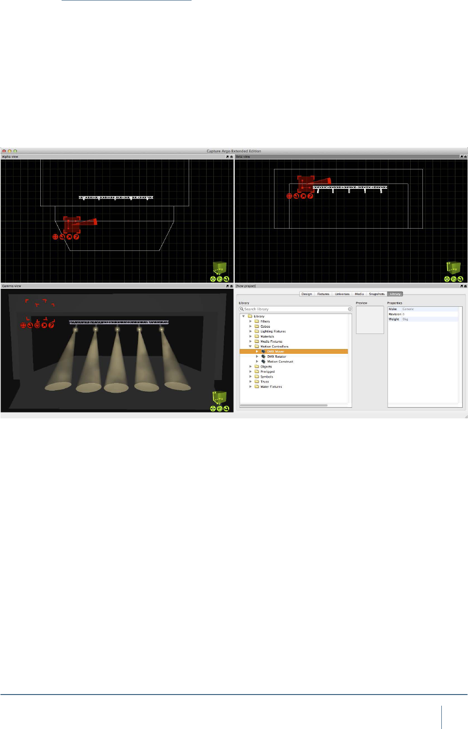
The DMX Motion Controllers are added to a project like
any other object in Capture - by dragging them from the
Library into one of the simulator views. Its best to look at
the controllers like lighting xtures, they are xtures in the
project. Its good practice to place the movers near to the
object they are controlling for ease of identication and ma-
nipulation, but they may be hidden from view if required.
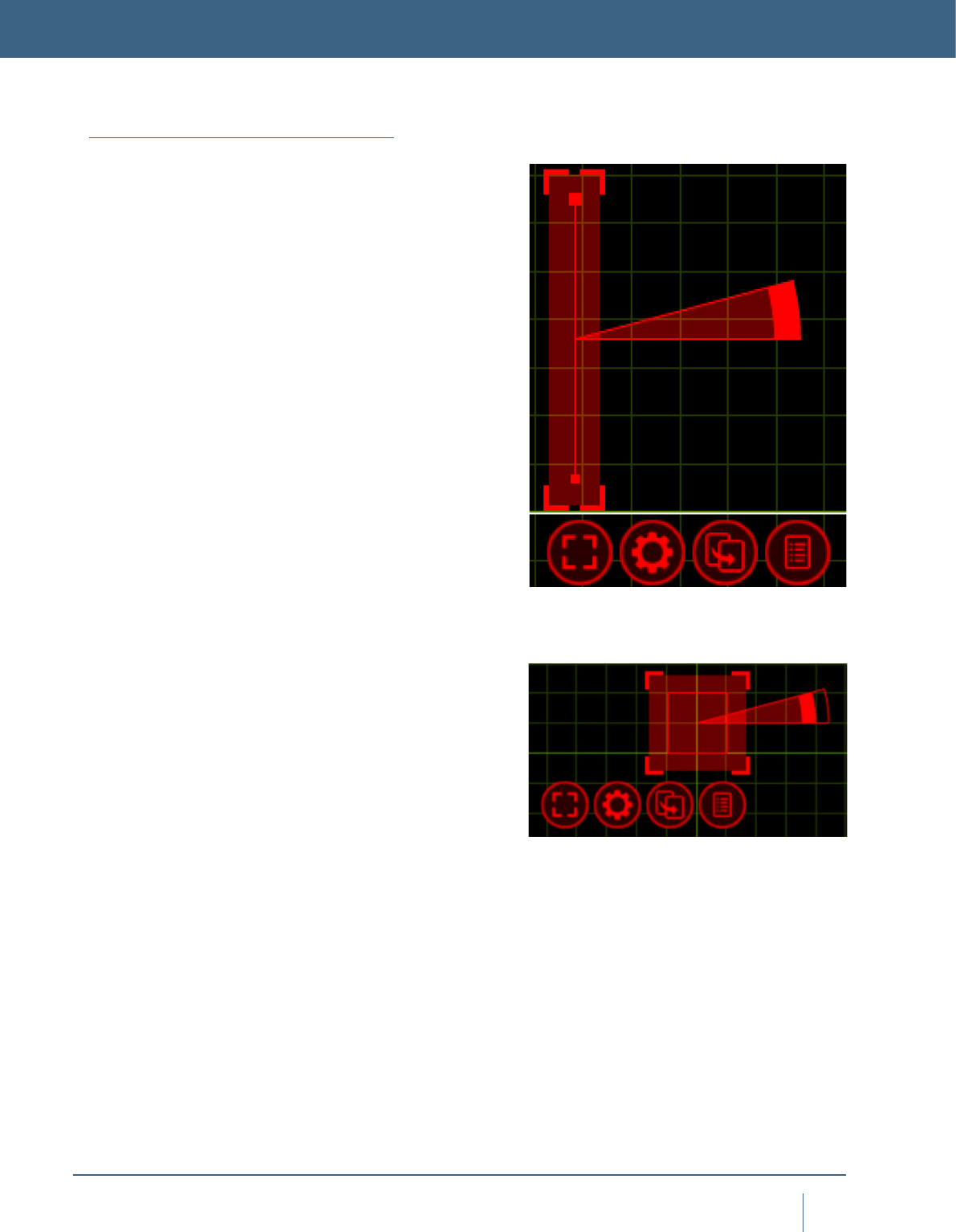
The DMX Mover, pictured to the right, has two blobs at
each end of the range. The thicker blob indicates the default
starting point of the object the Mover is attached to. The
thinner blob indicates the lowest point to Mover operates to.
The DMX Rotator, pictured to the right, is shown here as it
is seen in the “Orthographic Front” simulator view. The thick
blob in the middle of the circle indicates the central rotation
point that the object will rotate around. The line protruding
from the centre of the circle from the blob is the default start-
ing point. The circle itself indicates the range in which the
Rotator can operate. In this case, it is a full circle as the
Rotator has a range of 360 degrees.
MOTION CONTROLLERS
The DMX Mover
The DMX Rotator
68
MoTIon ConTrollers
Adding a DMX Mover
As we discussed, the rst type of DMX Motion Controller is
the DMX Mover.
The DMX Mover can move an object across a predened
range on the X Y Z axis. The mover can also be congured
to operate on only one axis, for example Y, so that the object
it is attached too will only move up and down.
Drag the DMX Mover into the project from the library. It
can be found under “Motion Controllers”. Position it near
to the truss it will be linked with, this will make it easier to
manage projects with multiple movers.
69
MoTIon ConTrollers
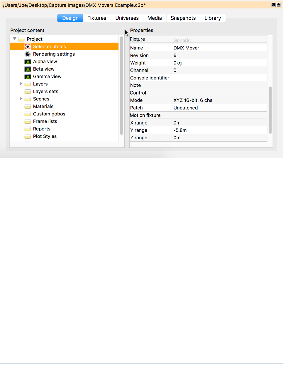
Select the mover and access its properties in the Project
Window.
Give the mover a name, using the “Unit” eld. Then con-
gure its properties to match the ranges in which you want
to mover to operate. In this case, the X and Z range will be 0
and the Y range will be -5.8m as we only want the mover to
move the truss up and down. 5.8m is the distance between
the truss and the oor.
70
MoTIon ConTrollers
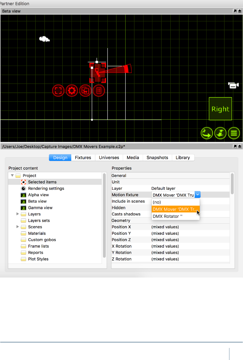
Select the Truss and the Fixtures you wish to move and
select the DMX Mover from the “Motion Fixture” property in
the Project Window.
71
MoTIon ConTrollers
The DMX Mover can now be selected and manipulated in
the Live view just like any other xture.
72
MoTIon ConTrollers
Adding a DMX Rotator
The second DMX Motion Controller is the DMX Rotator. The
Rotator can be used to rotate an object around on an axis
and within a specic range on that axis.
Now we add in a DMX Rotator and link the truss to it.
We then go on to link the Rotator to the DMX Mover we
created earlier. We call this “Chaining”. Once chained togeth-
er it means that we can select both the Mover & Rotator
and have individual control over both. The initial placement
of the Rotator is of great importance. Wherever the Rotator
is placed will be the point on which the rotation occurs. For
example, we place the Rotator in the middle of the truss
so that the truss Rotates around that point. Drag the DMX
Rotator into the project from the library. It can be found
under “Motion Controllers”.
73
MoTIon ConTrollers
Select the Truss and the Fixtures you wish to rotate and
select the DMX Rotator from the “Motion Fixture” property in
the Project Window.
Now, select the DMX Rotator and in the “Motion Fixture”
property, assign the Rotator to the DMX Mover. This “Chains”
the two motion controllers together so that when we select
both, the truss can be moved up and down and rotated at
the same time.
74
MoTIon ConTrollers
The DMX Mover & Rotator can now be selected and manip-
ulated in the Live view just like any other xtures.
Patching a DMX Motion Controller
Because a DMX Motion Controller is treated just like a
Fixture in Capture, it is patched in the same manner. You
can manually enter its patch and mode data in the prop-
erties tab of the Project Window, or you may use the drag
function to drag it onto the start channel of a particular uni-
verse. The patch property for the controller can be found
under “Control” in the selected items section of the Design
tab.

SNAPSHOTS & VIDEO RENDERING
76
snapshoTs & vIdeo renderIng
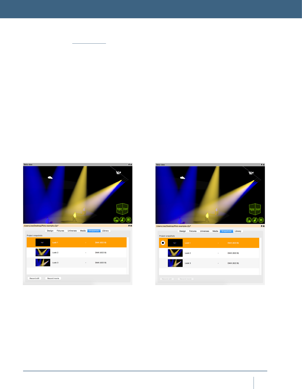
Snapshots
The still snapshots makes it possible to quickly move
between key lighting looks while making design changes,
even if no console is present. You can create high resolution
renders at any point, watermarked with your logo and project
information. Record movie snapshots including DMX, media
and motion of parts of your show for offline playback. Export
stand-alone 'Presentation' les that allow playback of all
your snapshots while in an interactive environment - on any
computer! Or if you prefer, render a high quality full-frame
rate video le of your movie snapshots. To record a snap-
shot, simply press either the Record Still or Record Movie
button in the snapshots tab of the Project Window. When
recording a movie look, an extra dialog box will appear that
allows you to set the FPS and start/stop. Snapshots can be
played back by pressing the Play/Stop buttons the appear to
the left of the Snapshot in the Snapshot tab.
SNAPSHOTS & VIDEO RENDERING

ADVANCED FILE MENU FUNCTIONS
78
advanCed fIle Menu funCTIons
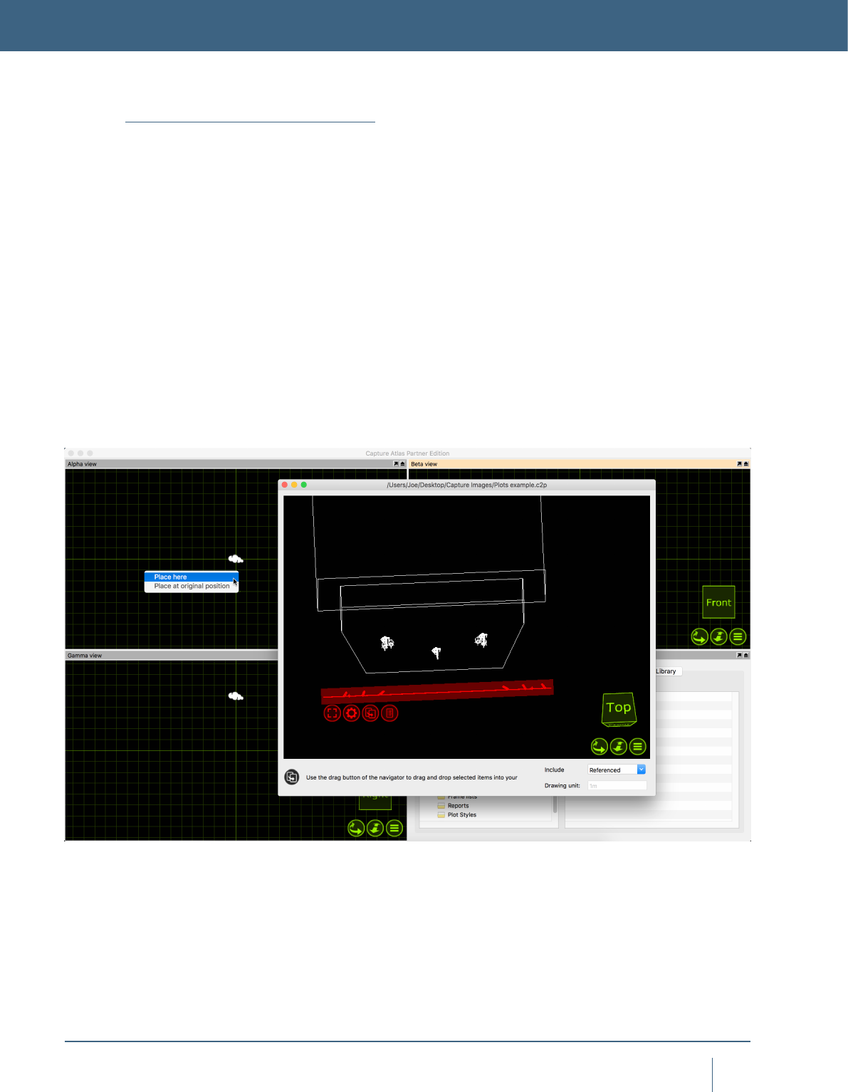
Using the Import Model tool
The Import Model feature is used to open up other project
les in parallel and allows you to copy items from other pro-
jects into the project you are working with (which is done
using the arrow navigator button). It was previously called
“Extract”. When opening older projects, a window may
appear telling you that some xtures have been updated
since the project you are trying to import from. Its good prac-
tice to hit “Update” so the new project gets the same version
of xtures as in the current library. Select “Import Model”
from the “File” menu, select the project you wish to import
things from. The selected project will open over the top of
your active project. Select some objects/xtures from the
project you want to import to your current project, use the
drag button to drag the items into your current project. You
have the option of placing them where you put the mouse
pointer or at their original position. Once you have nished,
simply close the project you imported objects from.
ADVANCED FILE MENU FUNCTIONS

79
advanCed fIle Menu funCTIons
Using the Import Data Tool
The Import Data tool can be found in the “File” Menu, it
allows you to import a CSV or Excel le containing infor-
mation about a rig to save time with assigning units, cir-
cuits, patches etc. The Export Data tool, covered in the
next section, denes the format of import and export.
Using Import, you can bring anything from the below table
between Capture project les. The best way to explore how
Import works is to make a Capture project with some x-
tures, assign some Units, Circuits, Patch, Channel and gobo
information to the xtures. Use the Export tool as featured in
the previous section, and then you can use the information
Exported to re-apply the same information for the xtures in
a new project.
Drawing le format interchange
Capture is able to import drawing information from other
softwares using the industry standard le formats described
below.
Autodesk DXF / DWG
The DXF format is a relatively simple text based format
useful to transfer smaller models and drawings of simple
nature. The more complex DWG format can contain more
complex information such as solid (ACIS) shapes and ma-
terials. Both the DXF and DWG formats stand out in the
fact that they do not enforce a model object hierarchy – a
drawing could consist of loosely scattered polygons only. As
this is a problem for Capture, all drawing content that does
not belong to a “block” will be grouped by layer and present-
ed as solid objects in Capture. Capture does not currently
support material information in these formats.
3D Studio 3DS
The 3DS le format was the native format for the early ver-
sions of 3D Studio, a very popular 3D modeling software. It is
rich in material settings and information required to produce
very realistic models. Capture successfully handles most of
the information in a 3DS le, however some of the more ad-
vanced material properties are not supported. 3DS textures
are not embedded inside the 3DS le but loosely packaged,
typically in a folder alongside the 3DS le itself. Be careful
to take this into account when sending and receiving 3DS
les! There is a rich amount of 3DS les available on the
internet. However, many of these have been converted from
other formats using automatic conversion tools of question-
able quality.
LightWave OBJ
The OBJ le format was developed by Wavefront
Technologies for its Advanced Visualizer animation package
in the 1980s. It is a simple and text based, yet very com-
petent le format. As with the 3DS format, OBJ les do not
have material textures embedded. Instead they are loosely
packaged alongside the OBJ le, typically in a separate
folder.
Fixture Filters
Optics Gobos
Wattage Accessories
Unit Note
Circuit Weight
Channel Position X
Patch Position Y
DMX Mode Position Z
DMX Channels Focus Pan
Layer Focus Tilt
Focus
80
advanCed fIle Menu funCTIons
Sketchup SKP
The SKP format is the native format of Trimble’s Sketchup
make and Sketchup Pro software packages. Capture reads
lines, surfaces, blocks, groups, materials and layers from
SKP les. While Sketchup supports double-sided materials,
Capture does not and will favor the front material over the
back material. Capture will also preserve block and group
transformations (useful for replace xture operations) as
long as no lines or surfaces in the group have been subject
to mirroring.
Using the Export Data Tool
The Export Data tool in the File menu can be used to export
a CSV le of the xtures in the project and their associated
data. Although the le will open in any plain text reader, its
best to open the le in a program such as Excel or Numbers.
To export, go to the “File” menu, select “Export data..” and
select the location you wish to store the exported le. Hit
“Save” and the le will be exported. The following data will
be exported and formatted into columns.
Using the Export Focus Sheets Tool
The export focus sheets feature creates a set of images,
one per xture (or as congured in the conguration dialog
presented), giving you a view out through the aperture of
the xture. It requires you to pick a folder into which the
images are placed. The feature relies on having assigned
“units” within the project, this can be done by using the
“Sequential Unit” feature discussed earlier in the manual.
Fixtures that do not have a unit number assigned will not
be exported. You may create focus sheets based on layer
sets, this allows for you to only export certain groups of x-
tures. Simply make a layer with only the xtures you wish to
export, assign it to a layer set, then select that layer set in
the export options window. If you only want to export focus
sheets for the selected xtures, set the “selected xtures
only” option to “Yes” in the export options.
Fixture Filters
Optics Gobos
Wattage Accessories
Unit Note
Circuit Weight
Channel Position X
Patch Position Y
DMX Mode Position Z
DMX Channels Focus Pan
Layer Focus Tilt
Focus
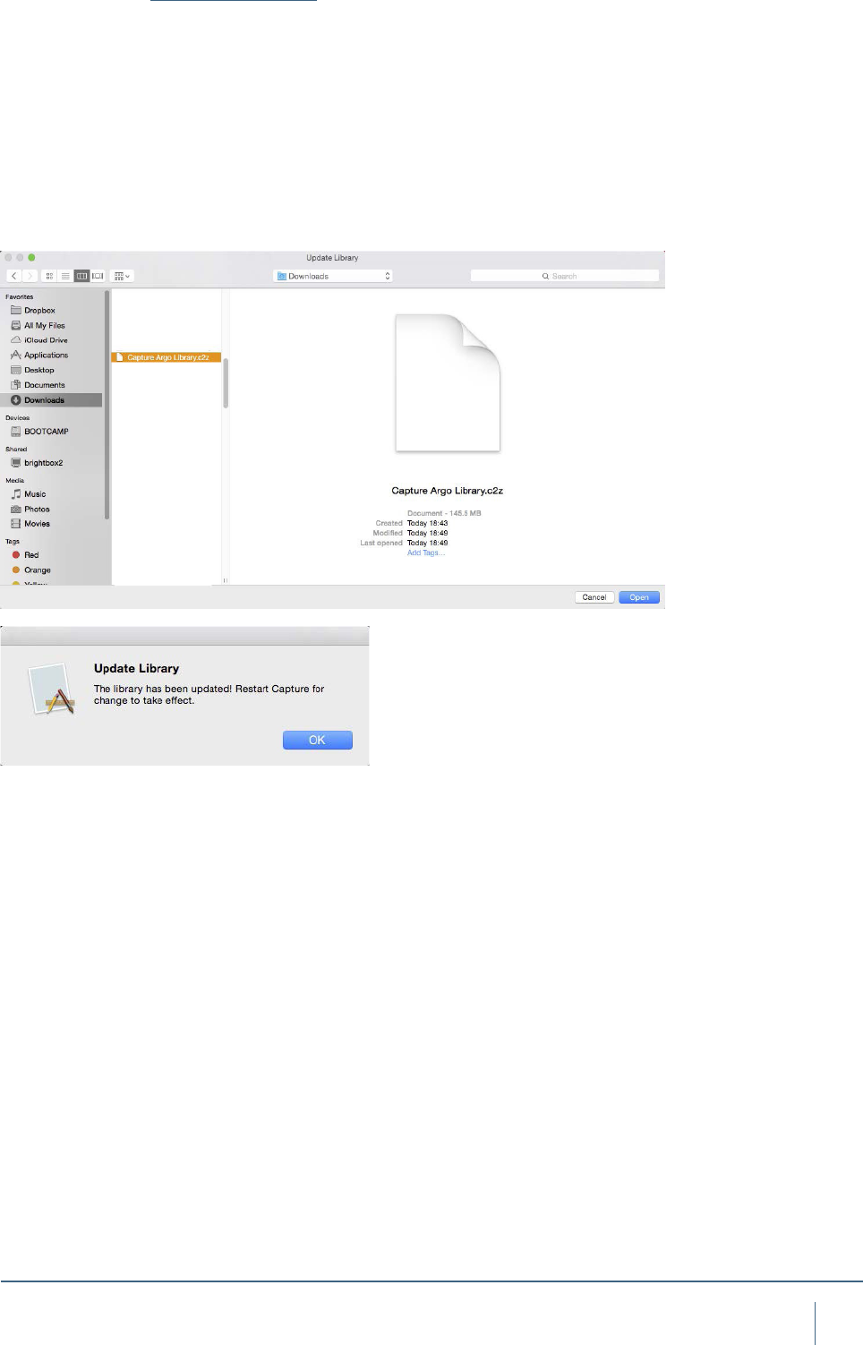
81
advanCed fIle Menu funCTIons
Update Library
Occasionally, it is necessary to update the Fixture Library in
between main software releases. This can be accomplished
by going to the downloads page of the Capture website
http://www.capturesweden.com/Download/Standard.aspx
and downloading the latest Library le.
Note that the library le has a .c2z le extension.
In Capture, go to the Tools menu. Select “Library Update”
and choose the .c2z le you downloaded. Capture will install
this latest library le and then prompt you to restart.

TROUBLESHOOTING

83
TroubleshooTIng
Troubleshooting
Should you run into any problems, do not hesitate to contact
us at support@capturesweden.com.
Graphics and video driver related problems
Capture is a professional visualization software and has
high demands on video cards and their drivers. In case of
problems, the following may help:
• Updating the video driver
• Trying different screen congurations (primary screen,
number of screens and maybe even screen resolutions)
• Updating your operating system
• Upgrading your graphics card
IP networking problems
If your computer is set up with multiple IP addresses,
Capture will ask you to select one of them as the primary.
This is important for many protocols and the option required
to set is available in the Options dialog from the Tools menu.
Windows networking problems
If your computer is not connected to a network at all but
you wish to work with software based controllers on the
same computer it may be necessary to install the Microsoft
Loopback adapter. The process is simple and described at
http://support.microsoft.com/kb/839013.
macOS networking problems
If you are experiencing problems connecting Capture to
your console or offline software under macOS, it may be
worth turning on an off the macOS rewall. This is done in
the System Preferences, under Security & Privacy.
TROUBLESHOOTING
