Celestron Advanced Series C10 N Users Manual C8N_C10n Master
C8-N to the manual 607bb938-cfc4-46b8-875a-ee89d406f537
2015-02-02
: Celestron Celestron-Advanced-Series-C10-N-Users-Manual-393279 celestron-advanced-series-c10-n-users-manual-393279 celestron pdf
Open the PDF directly: View PDF ![]() .
.
Page Count: 71
1
A
Ad
dv
va
an
nc
ce
ed
d
S
Se
er
ri
ie
es
s
A
Ad
dv
va
an
nc
ce
ed
d
S
Se
er
ri
ie
es
s
G
G
GT
T
T
I
IN
NS
ST
TR
RU
UC
CT
TI
IO
ON
N
M
MA
AN
NU
UA
AL
L
C
C8
8-
-N
N
/
/
C
C8
8-
-N
NG
GT
T
●
●
C
C1
10
0-
-N
N
/
/
C
C1
10
0-
-N
N
2
INTRODUCTION.................................................................................................................................................................................................... 4
Warning ................................................................................................................................................................................................................4
ASSEMBLY ............................................................................................................................................................................................................. 7
Setting up the Tripod.............................................................................................................................................................................................7
Attaching the Equatorial Mount............................................................................................................................................................................ 7
Attaching the Center Leg Brace ............................................................................................................................................................................ 8
Installing the Counterweight Bar ..........................................................................................................................................................................8
Installing the Counterweight .................................................................................................................................................................................9
Attaching the Hand Control Holder ......................................................................................................................................................................9
Attaching the Slow Motion Knobs........................................................................................................................................................................9
Attaching the Telescope Tube to the Mount........................................................................................................................................................10
Installing the Finderscope ................................................................................................................................................................................... 11
Installing the Eyepieces....................................................................................................................................................................................... 11
Balancing the Tube in R.A..................................................................................................................................................................................12
Adjusting the Mount ........................................................................................................................................................................................... 13
Adjusting the Mount in Altitude........................................................................................................................................................13
Adjusting the Mount in Azimuth....................................................................................................................................................... 14
Attaching the Declination Cables (For GT Models Only) ...................................................................................................................................14
Powering the Telescope ...................................................................................................................................................................................... 14
HAND CONTROL.................................................................................................................................................................................................15
Hand Control Operation...................................................................................................................................................................................... 16
Alignment Procedures......................................................................................................................................................................................... 17
Startup Procedure................................................................................................................................................................................................ 17
Auto Align ..........................................................................................................................................................................................................18
Auto Three-Star Align ........................................................................................................................................................................................18
Quick-Align ........................................................................................................................................................................................................ 19
Last Alignment ................................................................................................................................................................................................... 19
Re-Alignment......................................................................................................................................................................................................19
Object Catalog .................................................................................................................................................................................................... 20
Selecting an Object ...........................................................................................................................................................................20
Slewing to an Object ......................................................................................................................................................................... 20
Finding Planets.................................................................................................................................................................................. 20
Tour Mode ........................................................................................................................................................................................ 21
Constellation Tour............................................................................................................................................................................. 21
Direction Buttons .............................................................................................................................................................................. 21
Rate Button .......................................................................................................................................................................................21
Setup Procedures................................................................................................................................................................................................. 22
Tracking Mode..........................................................................................................................................................................................22
Tracking Rate............................................................................................................................................................................................22
Date/Time .................................................................................................................................................................................................22
User Defined Objects ................................................................................................................................................................................22
Get RA/DEC ............................................................................................................................................................................................. 23
Goto R.A/Dec............................................................................................................................................................................................23
Identify......................................................................................................................................................................................................23
Precise GoTo..................................................................................................................................................................................... 24
Scope Setup Features ........................................................................................................................................................................ 24
Setup Time-Site.........................................................................................................................................................................................24
Anti-backlash ............................................................................................................................................................................................24
Filter Limits .............................................................................................................................................................................................. 24
Direction Buttons ...................................................................................................................................................................................... 25
Goto Approach.......................................................................................................................................................................................... 25
Autoguide Rates........................................................................................................................................................................................25
Azimuth Limits ......................................................................................................................................................................................... 25
East/West Filtering.................................................................................................................................................................................... 26
Utility Features ...................................................................................................................................................................................................26
Calibrate Goto........................................................................................................................................................................................... 26
Home Position........................................................................................................................................................................................... 26
Polar Align................................................................................................................................................................................................ 26
Light Control............................................................................................................................................................................................. 27
Factory Settings.........................................................................................................................................................................................27
Version...................................................................................................................................................................................................... 27
Get Alt-Az.................................................................................................................................................................................................27
Goto Alt-Az .............................................................................................................................................................................................. 27
Hibernate................................................................................................................................................................................................... 27
Turn On/Off GPS...................................................................................................................................................................................... 27
3
TELESCOPE BASICS .......................................................................................................................................................................................... 29
Image Orientation ............................................................................................................................................................................................... 29
Focusing..............................................................................................................................................................................................................30
Aligning the Finderscope .................................................................................................................................................................................... 30
Calculating Magnification...................................................................................................................................................................................30
Determining Field of View ................................................................................................................................................................................. 31
General Observing Hints..................................................................................................................................................................................... 31
ASTRONOMY BASICS........................................................................................................................................................................................ 32
The Celestial Coordinate System ........................................................................................................................................................................ 32
Motion of the Stars..............................................................................................................................................................................................33
Finding the North Celestial Pole ......................................................................................................................................................................... 35
Declination Drift Method of Polar Alignment..................................................................................................................................................... 36
CELESTIAL OBSERVING.................................................................................................................................................................................. 37
Observing the Moon............................................................................................................................................................................................ 37
Lunar Observing Hints........................................................................................................................................................................................ 37
Observing the Planets..........................................................................................................................................................................................37
Observing the Sun............................................................................................................................................................................................... 37
Solar Observing Hints......................................................................................................................................................................................... 38
Observing Deep Sky Objects .............................................................................................................................................................................. 38
Seeing Conditions...............................................................................................................................................................................................38
Transparency....................................................................................................................................................................................................... 38
Sky Illumination..................................................................................................................................................................................................38
Seeing ................................................................................................................................................................................................................. 38
ASTROPHOTOGRAPHY .................................................................................................................................................................................... 40
Piggyback ...........................................................................................................................................................................................................40
Short Exposure Prime Focus Photography.......................................................................................................................................................... 41
Terrestrial Photography.......................................................................................................................................................................................42
Metering.............................................................................................................................................................................................................. 42
Reducing Vibration............................................................................................................................................................................................. 42
Auto Guiding ...................................................................................................................................................................................................... 43
TELESCOPE MAINTENANCE .......................................................................................................................................................................... 44
Care and Cleaning of the Optics..........................................................................................................................................................................44
Collimation ......................................................................................................................................................................................................... 44
OPTIONAL ACCESSORIES.............................................................................................................................................................................. 48
APPENDIX A – TECHNICAL SPECIFICATIONS......................................................................................................................................... 51
APPENDIX B – GLOSSARY OF TERMS......................................................................................................................................................... 52
APPENDIX C – LONGITUDES AND LATITUDES.......................................................................................................................................... 55
APPENDIX D – RS-232 CONNECTION............................................................................................................................................................. 60
APPENDIX E – TIME ZONE MAP..................................................................................................................................................................... 62
SKY MAPS............................................................................................................................................................................................................. 64

4
Congratulations on your purchase of the Celestron Advanced Series telescope (AST)! The Advanced Series of telescopes come in
standard (non-computerized) and computerized GT models. The Advanced Series is made of the highest quality materials to
ensure stability and durability. All this adds up to a telescope that gives you a lifetime of pleasure with a minimal amount of
maintenance. Furthermore, your Celestron telescope is versatile — it will grow as your interest grows.
The Advanced GT Series ushers in the next generation of computer automated telescopes. The Celestron Advanced GT series
continues in this proud tradition combining large aperture optics with the sophistication and ease of use of our computerized
GoTo mount.
If you are new to astronomy, you may wish to start off by using the built-in Sky Tour feature, which commands the telescopes to
find the most interesting objects in the sky and automatically slews to each one. Or if you are an experienced amateur, you will
appreciate the comprehensive database of over 40,000 objects, including customized lists of all the best deep-sky objects, bright
double stars and variable stars. No matter at what level you are starting out, the Advanced Series telescopes will unfold for you
and your friends all the wonders of the Universe.
Some of the many standard features of the Advanced GT include:
• Fully enclosed optical encoders for position location.
• Ergonomically designed mount that disassembles into compact and portable pieces.
• Database filter limits for creating custom object lists.
• Storage for programmable user defined objects; and
Many other high performance features!
The AST’s deluxe features combine with Celestron’s legendary optical systems to give amateur astronomers the most
sophisticated and easy to use telescopes available on the market today.
Take time to read through this manual before embarking on your journey through the Universe. It may take a few observing
sessions to become familiar with your telescope, so you should keep this manual handy until you have fully mastered your
telescope’s operation. The Advanced GT hand control has built-in instructions to guide you through all the alignment procedures
needed to have the telescope up and running in minutes. Use this manual in conjunction with the on-screen instructions provided
by the hand control. The manual gives detailed information regarding each step as well as needed reference material and helpful
hints guaranteed to make your observing experience as simple and pleasurable as possible.
Your telescope is designed to give you years of fun and rewarding observations. However, there are a few things to consider
before using your telescope that will ensure your safety and protect your equipment.
Warning
Y Never look directly at the sun with the naked eye or with a telescope (unless you have the proper
solar filter). Permanent and irreversible eye damage may result.
Y Never use your telescope to project an image of the sun onto any surface. Internal heat build-up can damage the telescope
and any accessories attached to it.
Y Never use an eyepiece solar filter or a Herschel wedge. Internal heat build-up inside the telescope can cause these devices to
crack or break, allowing unfiltered sunlight to pass through to the eye.
Never leave the telescope unsupervised, either when children are present or adults who may not be familiar with the correct
operating procedures of your telescope.
5
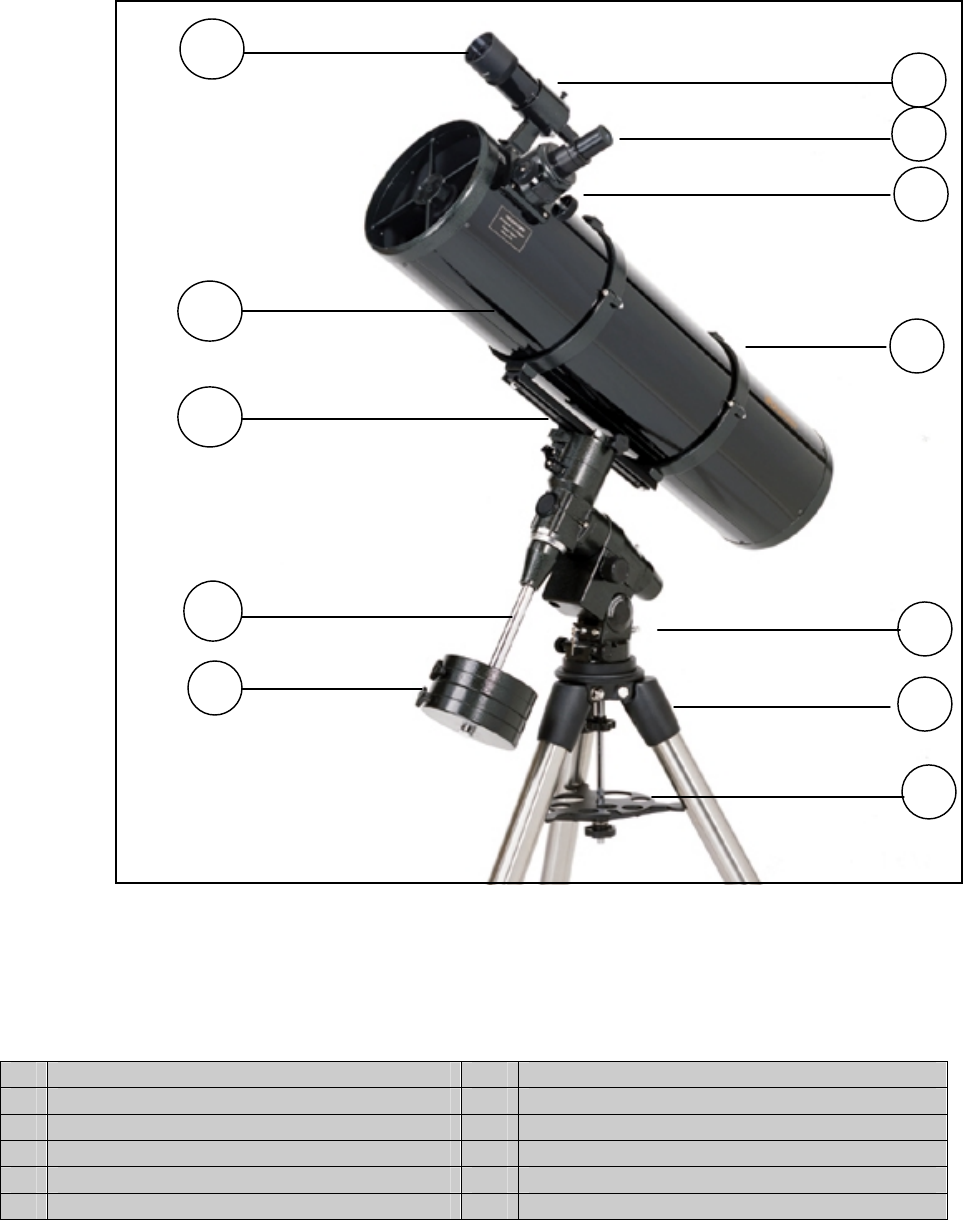
Fig 1-1 - The Advanced Series Newtonian
(C8-N Shown)
1. Finderscope 7. 2" Steel Tripod
2. Finderscope Bracket 8. Center Leg Brace / Accessory Tray
3. Eyepiece 9. Counterweights
4. Focuser 10. Counterweight Bar
5. Tube Rings 11. Dovetail Slide Bar
6. Latitude Adjustment Lever 12. Optical Tube
1
2
3
4
5
6
7
8
9
10
12
11
6
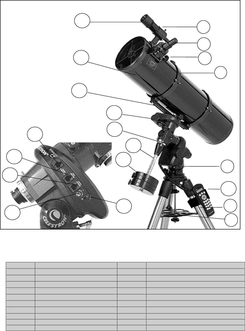
Fig 1-2 - The Advanced Series GT Newtonian
(C8-NGT Shown)
1. Finderscope 8. Center Leg Brace / Accessory Tray
2. Finderscope Bracket 9. Counterweights
3. Eyepiece 10. Counterweight Bar
4. Focuser 11. Dovetail Slide Bar
5. Tube Rings 12. Optical Tube
6. Latitude Adjustment Lever 13. Hand Control
7. 2" Steel Tripod 14. R.A. Motor Drive / Control Panel
CONTROL PANEL 15. Declination Motor Drive
A Hand Control Port
B DEC Motor Port D 12v Output Jack
C Autoguide Port E ON/OFF Switch
1
2
3
6
7
8
12
10
11
5
13
15
9
A
B
E
C
D
4
14
7
This section covers the assembly instructions for your Celestron Advanced Series Telescope (AST). Your AST
telescope should be set up indoor the first time so that it is easy to identify the various parts and familiarize yourself
with the correct assembly procedure before attempting it outdoor.
31061 / 31062 11047 / 11048
C8-N C10-N
Diameter 200mm (8.0") reflector 254mm (10") reflector
Focal Length 1000mm F/5 Parabola 1200mm F/4.7 Parabola
Eyepiece 20mm - 1.25" (50x) 20mm – 1.25" (60x)
Finderscope 9x50 9x50
Mount CG-5 Equatorial CG-5 Equatorial
Tripod 2" Stainless Steel 2" Stainless Steel
Software The Sky L1 The Sky L1
Counterweight 2-11lb 3-11lb
S
Se
et
tt
ti
in
ng
g
u
up
p
t
th
he
e
T
Tr
ri
ip
po
od
d
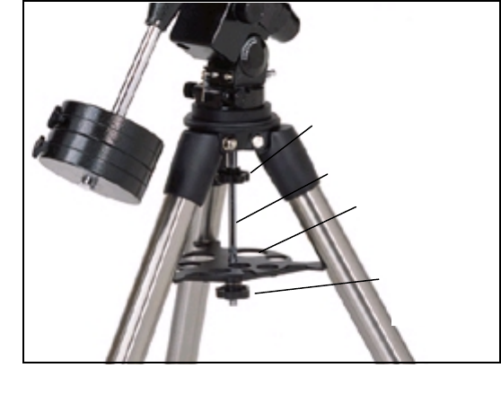
The CG-5 tripod comes with an all metal center leg brace / accessory tray to give rock solid support to the mount.
The tripod comes fully assembled with a metal plate, called the tripod head, that holds the legs together at the top.
In addition, there is a central rod that extends down from the tripod head that attaches the equatorial mount to the
tripod. To set up the tripod:
1. Stand the tripod upright and pull the tripod legs apart until each leg is fully extended. The tripod will now stand by
itself. Once the tripod is set up, you can adjust the height at
which it stands.
2. Loosen the lever on the leg clamp so that the tripod leg can be
adjusted.
3. Slide the center portion of the tripod leg away from the tripod
head until it is at the desired height.
4. Tighten the levers on each leg clamp to hold the legs in place.
A
At
tt
ta
ac
ch
hi
in
ng
g
t
th
he
e
E
Eq
qu
ua
at
to
or
ri
ia
al
l
M
Mo
ou
un
nt
t
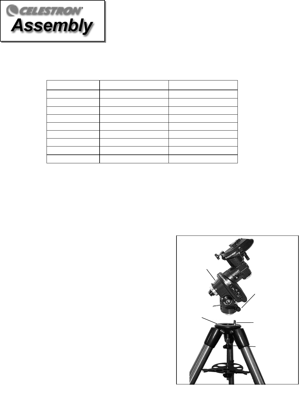
The equatorial mount allows you to tilt the telescope’s axis of
rotation so that you can track the stars as they move across the
sky. The CG-5 mount is a German equatorial mount that
attaches to the tripod head. On one side of the tripod head there
is a metal alignment peg for aligning the mount. This side of
the tripod will face north when setting up for an astronomical
observing session. To attach the equatorial head:
Equatorial
Moun
t
Tripod
Head Alignment
Peg
Azimuth
Alignment Screws
Mounting
Knob
Figure 2-3
8
1. Locate the azimuth adjustment screws on the equatorial mount.
2. Retract the screws so they no longer extend into the azimuth housing on the mount. Do NOT remove the screws
since they are needed later for polar alignment.
3. Hold the equatorial mount over the tripod head so that the azimuth housing is above the metal peg.
4. Place the equatorial mount on the tripod head so that the two are flush.
5. Tighten the knob (attached to the central rod) on the underside of the tripod head to hold the equatorial mount firmly
in place.
A
At
tt
ta
ac
ch
hi
in
ng
g
t
th
he
e
C
Ce
en
nt
te
er
r
L
Le
eg
g
B
Br
ra
ac
ce
e
1. Slide the accessory tray over the central rod so that each arm of the tray is pushing against the inside of the
tripod legs.
2. Thread the accessory tray knob on to the central rod and tighten.
I
In
ns
st
ta
al
ll
li
in
ng
g
t
th
he
e
C
Co
ou
un
nt
te
er
rw
we
ei
ig
gh
ht
t
B
Ba
ar
r
To properly balance the telescope, the mount comes with a counterweight bar and at least one counterweight
(depending on model). To install the counterweight
bar:
1. Locate the opening in the equatorial mount on the
DEC axis
2. Thread the counterweight bar into the opening until
tight.
3. Tighten the counterweight bar lock nut fully for added
support (see fig 2-5).
Once the bar is securely in place you are ready to
attach the counterweight.
Since the fully assembled telescope can be quite heavy, position the mount so that the polar axis is pointing
towards north before the tube assembly and counterweights are attached. This will make the polar alignment
procedure much easier.
Figure 2-4
Figure 2-3
Mounting Knob
Central Rod
Accessory Tray
Accessory
Tray Knob
9
I
In
ns
st
ta
al
ll
li
in
ng
g
t
th
he
e
C
Co
ou
un
nt
te
er
rw
we
ei
ig
gh
ht
t
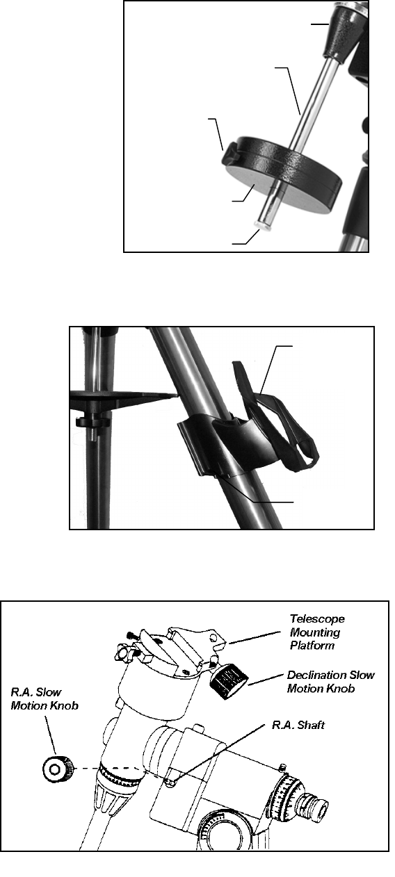
Depending on which AST telescope you have, you will receive either two or three counterweights. To install the
counterweight(s):
1. Orient the mount so that the counterweight bar points toward the
ground .
2. Remove the counterweight safety screw on the end of the
counterweight bar (i.e., opposite the end that attaches to the mount).
3. Loosen the locking screw on the side of the counterweight.
4. Slide the counterweight onto the shaft (see Figure 2-5).
5. Tighten the locking screw on the side of the weight to hold the
counterweight in place.
6. Replace the counterweight safety screw.
A
At
tt
ta
ac
ch
hi
in
ng
g
t
th
he
e
H
Ha
an
nd
d
C
Co
on
nt
tr
ro
ol
l
H
Ho
ol
ld
de
er
r
(
(A
Ad
dv
va
an
nc
ce
ed
d
G
GT
T
M
Mo
od
de
el
ls
s
O
On
nl
ly
y)
)
The Advanced GT telescope models come with a hand control
holder to place the computerized hand control. The hand control
holder comes in two pieces: the leg clamp that snaps around the
tripod leg and the holder which attaches to the leg clamp. To
attach the hand control holder:
1. Place the leg clamp up against one of the tripod legs and
press firmly until the clamp wraps around the leg.
2. Slide the back of the hand control holder downward into
the channel on the front of the legs clamp (see Fig 2-6)
until it snaps into place.
A
At
tt
ta
ac
ch
hi
in
ng
g
t
th
he
e
S
Sl
lo
ow
w
M
Mo
ot
ti
io
on
n
K
Kn
no
ob
bs
s
(
(F
Fo
or
r
N
No
on
n-
-G
GT
T
M
Mo
od
de
el
ls
s
O
On
nl
ly
y)
)
The Advanced Series (non-GT models) comes with
two slow motion control knobs that allows you to
make fine pointing adjustments to the telescope in
both R.A. and Declination. To install the knobs:
1. Locate the hard plastic shell under the R.A. shafts.
2. Remove either of the two oval tabs by pulling tightly.
3. Line up the flat area on the inner portion of the R.A.
slow motion knob with the flat area on the R.A. shaft
(see Fig 2-7).
4. Slide the R.A. slow motion knob onto the R.A. shaft.
Hand Control
Holder
Leg Clamp
Figure 2-6
Figure 2-7
Counterweigh
t
Safety Screw
Counterweight
Bar
Locking Screw
Figure 2-5
Counterweight Bar
Locking Nu
t
10
The knob is a tension fit, so sliding it on holds it in place. As mentioned above, there are two R.A. shafts, one on
either side of the mount. It makes no difference which shaft you use since both work the same. Use whichever one
you find more convenient. If, after a few observing sessions, you find the R.A. slow motion knob is more accessible
from the other side, pull firmly to remove the knob, then install it on the opposite side.
5. The DEC slow motion knob attaches in the same manner as the R.A. knob. The shaft that the DEC slow motion
knob fits over is toward the top of the mount, just below the telescope mounting platform. Once again, you have two
shafts to choose from. Use the shaft that is pointing toward the ground. This makes it easy to reach while looking
through the telescope, something which is quite important when you are observing.
A
At
tt
ta
ac
ch
hi
in
ng
g
t
th
he
e
T
Te
el
le
es
sc
co
op
pe
e
T
Tu
ub
be
e
t
to
o
t
th
he
e
M
Mo
ou
un
nt
t
The telescope attaches to the mount via a dovetail slide bar mounting bracket which is mounted along the
bottom of the telescope tube. Before you attach the optical tube,
make sure that the declination and right ascension clutch
knobs are tight. This will ensure that the mount does not move
suddenly while attaching the telescope. To mount the telescope
tube:
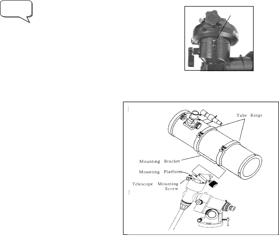
In order for the GT computerized mount to function properly,
before installing the optical tube, the mounting platform must be
positioned so that the Declination Index Marks are aligned (see Fig
2-8).
1 Locate the mounting bracket from the box containing the equatorial
mount head.
2 Attach the mounting bracket to the tube rings so that the tapered (narrow) end is against the bottom of the tube
rings.
3 Loosen the hand knob on the side of the
CG-5 mount.
4 Slide the mounting bracket that is attached
to the bottom of the tube rings into the recess
on the top of the mounting platform (see figure
2-9).
5 Tighten the telescope mounting screw on
the CG-5 mount to hold the telescope in place.
6 Hand tighten the mounting platform safety
screw until the tip touches the side of the
mounting bracket.
NOTE: Never loosen any of the knobs on
the telescope tube or mount. Also, be sure
that the open end of the telescope is
pointing away from the ground at all times.
Figure 2-9
Advanced
GT Users! Declination
Index Marks
Figure 2-8
11
I
In
ns
st
ta
al
ll
li
in
ng
g
t
th
he
e
F
Fi
in
nd
de
er
rs
sc
co
op
pe
e
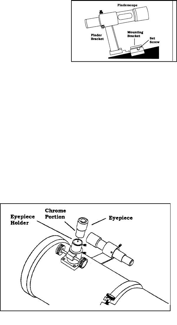
To install the finderscope onto the telescope you must first mount the finderscope through the finder bracket and
then attach it to the telescope. Toward the front of the telescope tube, near the focusing assembly, there is a small
bracket with a set screw in it. This is where the finderscope bracket will be mounted. To install the finderscope:
1. Slide the rubber O-ring over the eyepiece end of the finderscope and roll it 2/3 of the way up the
finderscope.
2. Insert the eyepiece end of the finderscope through the
bracket until the O-ring presses tightly between the finder
and the inside of the bracket.
3. Tighten the adjustment screws until they make contact with
the finderscope body.
4. Locate the mounting bracket near the front (open) end of the
telescope.
5. Loosen the set screw on the mounting bracket on the telescope.
6. Slide the finder bracket (attached to the finderscope) into the mounting bracket on the telescope.
7. The finderscope bracket will slide in from the back. The finderscope should be oriented so that the
objective lens is toward the front (open) end of the telescope.
8. Tighten the set screw on the mounting bracket to hold the finderscope in place.
For information on aligning your finderscope, see Telescope Basics section of this manual.
I
In
ns
st
ta
al
ll
li
in
ng
g
t
th
he
e
E
Ey
ye
ep
pi
ie
ec
ce
es
s
The eyepiece, or ocular as it is also called, is an optical element that magnifies the image focused by the telescope.
Without the eyepiece it would be impossible to use the telescope visually. The eyepiece fits directly into the
eyepiece holder. To attach an ocular:
1. Loosen the set screw on the eyepiece
holder so that it does not obstruct the
inner diameter of the eyepiece holder.
2. Slide the chrome portion of the
eyepiece into the eyepiece holder.
3. Tighten the set screw to hold the
eyepiece in place.
To remove the eyepiece, loosen the set
screw on the eyepiece holder and slide
Figure 2-10
Fi
g
ure 2-11
12
the eyepiece out. You can replace it with another ocular.
Eyepieces are commonly referred to by focal length which is printed on the
eyepiece barrel. The longer the focal length (i.e., the larger the number) the
lower the eyepiece power and the shorter the focal length (i.e., the smaller the
number) the higher the magnification. Generally, you will use low-to-
moderate power when viewing.
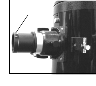
Your telescope can use eyepieces with both a 1-1/4" barrel diameter and 2"
barrel diameter. To use a 2" barrel eyepiece, the 1 1/4" eyepiece adapter must
first be removed and replaced with the included 2" eyepiece adapter. To do
this, simply loosen the two chrome thumbscrews located around the focuser
barrel (see figure 2-12) and remove the 1 1/4" adapter. Once removed, a 2"
eyepiece adapter can be inserted directly into the focuser barrel and secured with the
two thumb screws.
B
Ba
al
la
an
nc
ci
in
ng
g
t
th
he
e
T
Tu
ub
be
e
i
in
n
R
R.
.A
A.
.
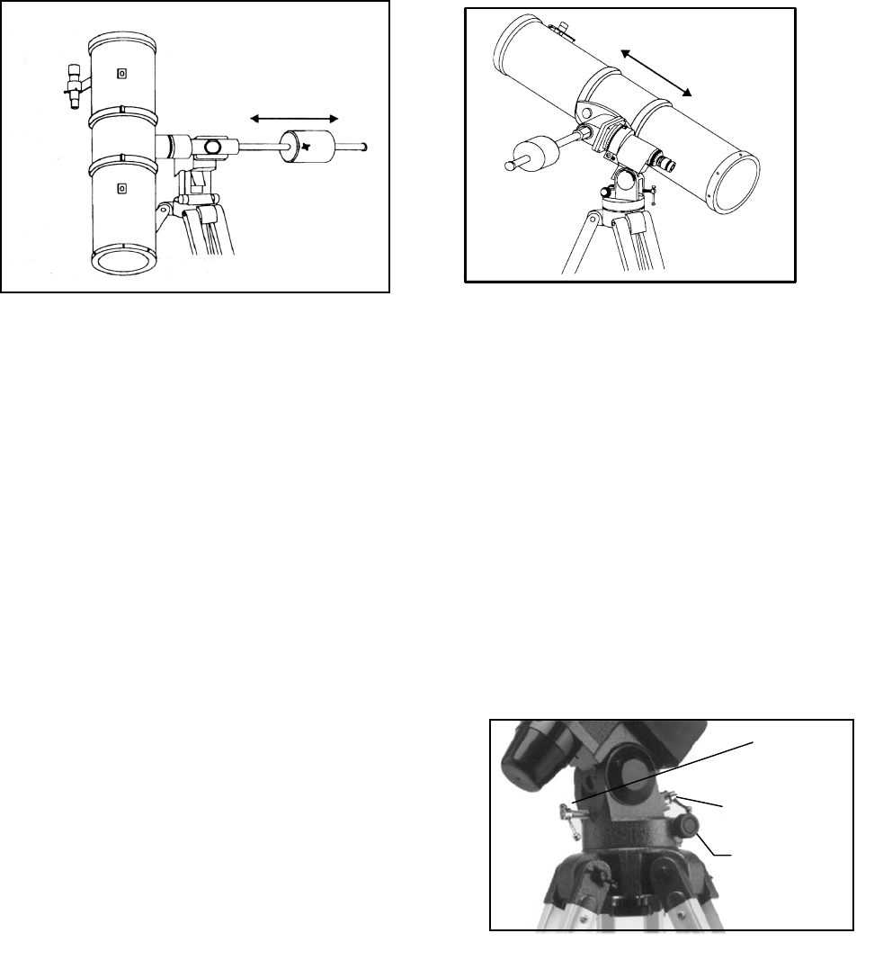
To eliminate undue stress on the mount, the telescope should be properly balanced around the polar axis. In
addition, proper balancing is crucial for accurate tracking if using an optional motor drive. To balance the mount:
1. Release the R.A. Clamp (figure 2-16) and position the telescope off to one side of the mount (make sure that the
mounting bracket screw is tight). The counterweight bar will extend horizontally on the opposite side of the mount
(see figure 2-13).
2. Release the telescope — GRADUALLY — to see which way the telescope “rolls.”
3. Loosen the set screw on the counterweight.
4. Move the counterweight to a point where it balances the telescope (i.e., it remains stationary when the R.A. clamp is
released).
5. Tighten the set screw to hold the counterweight(s) in place.
These are general balance instructions and will reduce undue stress on the mount. When taking astrophotographs,
this balance process should be done for the specific area at which the telescope is pointing.
Balancing the Telescope in DEC
The telescope should also be balanced on the declination axis to prevent any sudden motions when the DEC clamp
(figure 2-16) is released. To balance the telescope in DEC:
1. Release the R.A. clamp and rotate the telescope so that it is on one side of the mount (i.e., as described in the
previous section on balancing the telescope in R.A.).
2. Lock the R.A. clamp to hold the telescope in place.
3. Release the DEC clamp and rotate the telescope until the tube is parallel to the ground (see figure 2-14).
4. Release the tube — GRADUALLY — to see which way it rotates around the declination axis. DO NOT LET GO
OF THE TELESCOPE TUBE COMPLETELY!
2" Eyepiece
Adapter
Fi
g
ure 2-12
13
5. Loosen the screws that hold the telescope tube inside the mounting rings and slide the telescope either forwards or
backwards until it remains stationary when the DEC clamp is released.
6. Tighten the tube ring screws firmly to hold the telescope in place.
Like the R.A. balance, these are general balance instructions and will reduce undue stress on the mount. When taking
astrophotographs, this balance process should be done for the specific area at which the telescope is pointing.
A
Ad
dj
ju
us
st
ti
in
ng
g
t
th
he
e
M
Mo
ou
un
nt
t
In order for a motor drive to track accurately, the telescope’s axis of rotation must be parallel to the Earth’s axis of
rotation, a process known as polar alignment. Polar alignment is achieved NOT by moving the telescope in R.A. or
DEC, but by adjusting the mount vertically, which is called altitude, and horizontally, which is called azimuth. This
section simply covers the correct movement of the telescope during the polar alignment process. The actual process
of polar alignment, that is making the telescope’s axis of rotation parallel to the Earth’s, is described later in this
manual in the section on “Polar Alignment.”
Adjusting the Mount in Altitude
• To increase the latitude of the polar axis, tighten the rear latitude adjustment screw and loosen the front screw (if
necessary).
• To decrease the latitude of the polar axis, tighten the front (under the counterweight bar) latitude adjustment screw
and loosen the rear screw (if necessary).
The latitude adjustment on the CG-5 mount has a range from
approximately 30° going up to 60°.
It is best to always make final adjustments in altitude by
moving the mount against gravity (i.e. using the rear latitude
adjustment screw to raise the mount). To do this you should
loosen both latitude adjustment screws and manually push the
front of the mount down as far as it will go. Then tighten the
rear adjustment screw to raise the mount to the desired
latitude.
Figure 2-14
Figure 2-13
Figure 2-15
Azimuth
Adjustment
Knobs
Rear Latitude
Adjustment
Screw
Front Latitude
Adjustment Screw
14
For Advanced GT users, it may be helpful to remove the front latitude adjustment screw completely. This will allow
the mount to reach lower latitudes without the screw coming into contact with the R.A. motor assembly. To remove
the latitude screw, first use the rear screw to raise the mount head all the way up. Then remove the front latitude
screw completely. Now you should be able to manually move the mount head all the way to its lowest latitude. Now,
using only the rear screw, raise the mount to your desired latitude.
Adjusting the Mount in Azimuth
For rough adjustments in azimuth, simply pick up the telescope and tripod and move it. For fine adjustments in
azimuth:
1. Turn the azimuth adjustment knobs located on either side of the azimuth housing (see Fig 2-15). While standing
behind the telescope, the knobs are on the front of the mount.
• Turning the right adjustment knob clockwise moves the mount toward the right.
• Turning the left adjustment knob clockwise moves the mount to the left.
Both screws push off of the peg on the tripod head, which means you may have to loosen one screw while tightening
the other. The screw that holds the equatorial mount to the tripod may have to be loosened slightly.
Keep in mind that adjusting the mount is done during the polar alignment process only. Once polar aligned, the
mount must NOT be moved. Pointing the telescope is done by moving the mount in right ascension and declination,
as described earlier in this manual.
A
At
tt
ta
ac
ch
hi
in
ng
g
t
th
he
e
D
De
ec
cl
li
in
na
at
ti
io
on
n
C
Ca
ab
bl
le
e
(
(F
Fo
or
r
G
GT
T
M
Mo
od
de
el
ls
s
O
On
nl
ly
y)
)
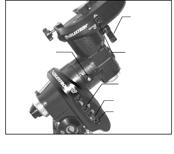
The Advanced Series mount comes with a declination cable that connects from the R.A. motor drive electronic panel
to the Dec motor drive. To attach the motor cable:
Locate the Declination cable and plug one end of the
cable into the port on the electronics panel labeled
DEC Port and plug the other end of the cable into the
port located on the declination motor drive (see Fig
2-16).
P
Po
ow
we
er
ri
in
ng
g
t
th
he
e
T
Te
el
le
es
sc
co
op
pe
e
The Advanced GT can be powered by the supplied
car battery adapter or optional 12v AC adapter. Use
only adapters supplied by Celestron. Using any other
adapter may damage the electronics or cause the
telescope not to operate properly, and will void your
manufacturer's warranty.
1. To power the telescope with the car battery
adapter (or 12v AC adapter), simply plug
the round post into the 12v outlet on the
electronic panel and plug the other end into your cars cigarette lighter
outlet or portable power supply (see Optional Accessories). Note: to
prevent the power cord from being accidentally pulled out, wrap the
power cord around the strain relief located below the power switch.
2. Turn on the power to the telescope by flipping the switch, located on the electronics panel, to the "On"
position.
Figure 2-16
Declination Cable
Output Port
Declination Cable
Input Port
12v Power Input
On/Off Switch
DEC Locking
Clamp
R.A. Locking
Clamp
Figure 2-16
15
The Advanced Series GT, computerized version of each telescope has a hand controller designed to give you instant
access to all the functions that your telescope has to offer. With automatic slewing to over 40,000 objects, and
common sense menu descriptions, even a beginner can master its variety of features in just a few observing sessions.
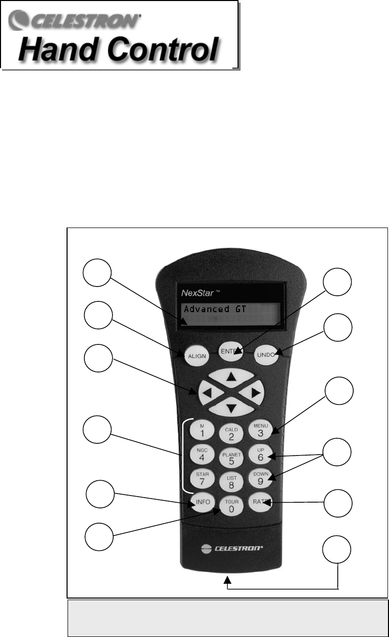
Below is a brief description of the individual components of the computerized hand controller:
1. Liquid Crystal Display (LCD) Window: Has a dual-line, 16 character display screen that is backlit for
comfortable viewing of telescope information and scrolling text.
2. Align: Instructs the telescope to use a selected star or object as an alignment position.
3. Direction Keys: Allows complete control of the telescope in any direction. Use the direction keys to move
the telescope to the initial alignment stars or for centering objects in the eyepiece.
Figure 3-1
The Advanced GT Hand Control
1
2
3
7
8
9
10
4
5
6
11
12

16
4. Catalog Keys: The Advanced Series has keys on the hand control to allow direct access to each of the
catalogs in its database. The hand control contains the following catalogs in its database:
Messier – Complete list of all Messier objects.
NGC – Complete list of all the deep-sky objects in the Revised New General Catalog.
Caldwell – A combination of the best NGC and IC objects.
Planets - All 8 planets in our Solar System plus the Moon.
Stars – A compiled list of the brightest stars from the SAO catalog.
List – For quick access, all of the best and most popular objects in the Advanced GT database have
been broken down into lists based on their type and/or common name:
Named Stars Common name listing of the brightest stars in the
sky.
Named Objects Alphabetical listing of over 50 of the most popular
deep sky objects.
Double Stars Numeric-alphabetical listing of the most visually
stunning double, triple and quadruple stars in the
sky.
Variable Stars Select list of the brightest variable stars with the
shortest period of changing magnitude.
Asterisms A unique list of some of the most recognizable star
patterns in the sky.
CCD Objects A custom list of many interesting galaxy pairs, trios
and clusters that are well suited for CCD imaging
with the Advanced GT telescope.
IC Objects A complete list of all the Index Catalog deep-sky
objects.
Abell Objects A custom list of the Abell Catalog deep-sky
galaxies.
Constellation A complete list of all 88 constellations.
5. Info: Displays coordinates and useful information about objects selected from the Advanced GT database.
6. Tour: Activates the tour mode, which seeks out all the best objects for the current date and time, and
automatically slews the telescope to those objects.
7. Enter: Pressing Enter allows you to select any of the Advanced GT functions and accept entered
parameters.
8. Undo: Undo will take you out of the current menu and display the previous level of the menu path. Press
Undo repeatedly to get back to a main menu or use it to erase data entered by mistake.
9. Menu: Displays the many setup and utilities functions such as tracking rates and user defined objects and
many others.
10. Scroll Keys: Used to scroll up and down within any of the menu lists. A double-arrow will appear on the
right side of the LCD when there are sub-menus below the displayed menu. Using these keys will scroll
through those sub-menus.
11. Rate: Instantly changes the rate of speed of the motors when the direction buttons are pressed.
12. RS-232 Jack: Allows you to interface with a computer and control the telescope remotely.
H
Ha
an
nd
d
C
Co
on
nt
tr
ro
ol
l
O
Op
pe
er
ra
at
ti
io
on
n
This section describes the basic hand control procedures needed to operate the GT Series Telescopes. These
procedures are grouped into three categories: Alignment, Setup and Utilities. The alignment section deals with the
initial telescope alignment as well as finding objects in the sky; the setup section discusses changing parameters
such as tracking mode and tracking rate; finally, the last section reviews all of the utilities functions such as
calibrating your mount, polar alignment and backlash compensation.

17
A
Al
li
ig
gn
nm
me
en
nt
t
P
Pr
ro
oc
ce
ed
du
ur
re
es
s
In order for the telescope to accurately point to objects in the sky, it must first be aligned to three known positions
(stars) in the sky. With this information, the telescope can create a model of the sky, which it uses to locate any
object with known coordinates. There are many ways to align your telescope with the sky depending on what
information the user is able to provide: Auto Align allows the telescope to select three stars and uses the entered
time/location information to align the telescope; Auto Three Star Align involves the same process as Auto Align,
however it allows the user to select which star to use to align the telescope. Quick-Align will ask you to input all the
same information as you would for the Auto Align procedure. However, instead of slewing to the alignment stars
for centering and alignment, the telescope bypasses this step and simply models the sky based on the information
given. Finally, Last Alignment restores your last saved star alignment and switch position. Last Alignment also
serves as a good safeguard in case the telescope should lose power.
S
St
ta
ar
rt
tu
up
p
P
Pr
ro
oc
ce
ed
du
ur
re
e
Before any of the described alignments are performed, the telescope mount needs to be positioned so that the index
marks are aligned on both the right ascension and declination axes (see Fig 2-8).
First index its switch position so that each axis has an equal amount of
travel to move in either direction. Once the index position has been set,
the hand control will display the last entered date and time information
stored in the hand control. Once the telescope is powered on:
1. Press ENTER begin the alignment process.
2. The hand control will ask the user to set the mount to its index
position. Move the telescope mount, either manually or with
the hand control, so that the index marked in both R.A. and
Dec are aligned (see Fig 2-8). Press Enter to continue.
3. The hand control will then display the last entered local time,
date, time zone, longitude and latitude.
• Use the Up/Down keys (10) to view the current
parameters.
• Press ENTER to accept the current parameters.
• Press UNDO to enter current date and time
information into the hand control. The following
information will be displayed:
Time - Enter the current local time for your area. You can
enter either the local time (i.e. 08:00), or you can enter
military time (i.e. 20:00 ).
• Select PM or AM. If military time was entered,
the hand control will bypass this step.
• Choose between Standard time or Daylight
Savings time. Use the Up and Down scroll buttons
(10) to toggle between options.
• Select the time zone that you are observing from. Again, use the Up and Down buttons (10) to
scroll through the choices. Refer to Time Zone map in Appendix for more information.
Date - Enter the month, day and year of your observing session.
• Finally, you must enter the longitude and latitude of the location of your observing site. Use
the table in Appendix C to locate the closest longitude and latitude for your current observing
location and enter those numbers when asked in the hand control, pressing ENTER after each
entry. Remember to select "West" for longitudes in North America and "North" for latitudes in
the North Hemisphere. For international cities, the correct hemisphere is indicated in the
Appendix listings.
4. Select one of the four alignment methods as described below.
Mount Calibration
A
fter an Auto Align is successfully
completed, the hand control will
display the message, Calibrating...
This automatic calibration routine is
necessary to calculate and
compensates for "cone" erro
r
inherent in all German equatorial
mounts. Cone error is the
inaccuracy that results from the
optical tube not being exactly
perpendicular to the mounts
declination axis as well as various
other inaccuracies such as backlash
in the mounts gears. The telescope
is able to automatically determine
the cone error value by always using
alignment stars on both sides of the
Meridian (see Figure 3-2).
Mechanical errors can be reduced
further by always centering
alignment stars using the up and
right arrow buttons as described in
the Pointing Accuracy box below.
18
Note: If incorrect information is entered into the hand control, the UNDO button acts like a back space button
allowing the user to re-enter the correct data.
A
Au
ut
to
o
A
Al
li
ig
gn
n
Auto Align allows the telescope to automatically choose three stars
(two on one side of the Meridian, and one on the opposite side) on
which to align itself. To Auto Align your telescope:
1. Select Auto Align from the alignment choices given.
Based on the date and time information entered, the
telescope will automatically select and go to a bright star
that is above the horizon.
• If for some reason the chosen star is not visible
(perhaps behind a tree or building) press UNDO to
automatically select the next bright star from the
database star list.
2. Once the telescope is finished slewing to your first
alignment star, the display will ask you to use the arrow
buttons to align the selected star with the crosshairs in the
center of the finderscope. Once centered in the finder,
press ENTER.
3. The display will then instruct you to center the star in the
field of view of the eyepiece. When the star is centered,
press ALIGN to accept this star as your first alignment
star.
4. After the first alignment star has been entered the telescope will automatically select a second alignment
star on the same side of the Meridian and have you repeat this procedure for that star.
5. For the third alignment star, the telescope will select a bright star on the opposite side of the Meridian and
slew to it. Once again center the star in the crosshairs of the finderscope and then center the star in the
eyepiece, pressing ENTER when complete.
When the telescope has been aligned on all three stars the display will read Alignment Successful, and you are
now ready to find your first object.
A
Au
ut
to
o
T
Th
hr
re
ee
e-
-S
St
ta
ar
r
A
Al
li
ig
gn
n
Auto Three-Star Alignment works much the same way as Auto Align, however
instead of automatically slewing to the alignment stars, the user is allowed to
select the alignment stars from a list. To use Auto Three-Star Align:
1. Select Auto Three Star Align from the alignment choices given.
2. The hand control will display a recommended alignment star to
begin.
• Press UNDO to display the next recommended star on the same
side of the Meridian, or
• Press the UP and DOWN arrows keys to scroll through the
compete list of available alignment stars to choose from.
3. Once the desired alignment star is displayed on the hand control
press ENTER to slew the telescope to the star.
4. As with the Auto Align procedure, you will be asked to center the
star in the crosshairs of the finderscope and then center the star in
the eyepiece, pressing ENTER when complete.
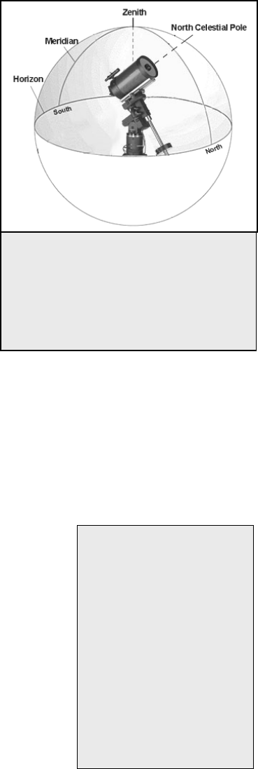
Figure 3-2
The Meridian is an imaginary line in the sk
y
that starts at the North celestial pole and
ends at the South celestial pole and passes
through the zenith. If you are facing South,
the meridian starts from your Southern
horizon and passes directly overhead to the
North celestial pole.
Pointing Accuracy
For the best possible
pointing accuracy, always
center the alignment stars
using the up arrow button
and the right arrow button.
A
pproaching from this
direction when looking
through the eyepiece will
eliminate much of the
backlash between the
gears and assures the
most accurate alignmen
t
possible.
19
NOTE: Although the telescope allows the user to select the alignment stars, for best all-sky pointing accuracy it is still necessary
to select two alignment stars on one side of the Meridian and the third star on the opposite side of the Meridian. For this reason,
the hand control will only display stars that are on the same side of the Meridian for the first two alignment stars, then will only
display stars on the opposite side of the Meridian for the third alignment star.
Q
Qu
ui
ic
ck
k-
-A
Al
li
ig
gn
n
Quick-Align uses all the date and time information entered at startup to align the telescope. However, instead of slewing to the
alignment stars for centering and alignment, the telescope bypasses this step and simply models the sky based on the information
given. This will allow you to roughly slew to the coordinates of bright objects like the moon and planets and gives the telescope
the information needed to track objects in any part of the sky (depending on accuracy of polar alignment). Quick-Align is not
meant to be used to accurately locate small or faint deep-sky objects or to track objects accurately for photography.
To use Quick-Align, simply select Quick Align from the alignment options and press ENTER. The telescope will automatically
use the entered date/time parameters to align itself with the sky and display Alignment Successful.
NOTE: Once a Quick-Align has been done, you can use the Re-alignment feature (see below) to improve your
telescopes pointing accuracy.
L
La
as
st
t
A
Al
li
ig
gn
nm
me
en
nt
t
The Last Alignment method will automatically recall the last stored index positions to continue using the alignment
that was saved when the telescope was last powered down. This is a useful feature should your telescope
accidentally lose power or be powered down.
NOTE: Just like with Quick-Align, you can use the Re-alignment feature (see below) to improve your telescopes
pointing accuracy after using the Last Alignment method. To maintain a more accurate alignment over a series of
observing sessions, use the Hibernate feature described later in this chapter.
R
Re
e-
-A
Al
li
ig
gn
nm
me
en
nt
t
The Advanced Series telescopes have a re-alignment feature which allows you to replace any of the original
alignment stars with a new star or celestial object. This can be useful in several situations:
• If you are observing over a period of a few hours, you may notice that your original two alignment
stars have drifted towards the west considerably. (Remember that the stars are moving at a rate of 15º
every hour). Aligning on a new star that is in the eastern part of the sky will improve your pointing
accuracy, especially on objects in that part of the sky.
• If you have aligned your telescope using the Quick-Align method, you can use re-align to align on
actual objects in the sky. This will improve the pointing accuracy of your telescope without having to
re-enter addition information.
To replace an existing alignment star with a new alignment star:
1. Select the desired star (or object) from the database and slew to it.
2. Carefully center the object in the eyepiece.
3. Once centered, press the UNDO button until you are at the main menu.
4. With Advanced GT displayed, press the ALIGN key on the hand control.
5. The display will then ask you which alignment star you want to replace. Use the UP and Down scroll keys
to select the alignment star to be replaced. It is usually best to replace the star closest to the new object.
This will space out your alignment stars across the sky.
6. Press ALIGN to make the change.

20
O
Ob
bj
je
ec
ct
t
C
Ca
at
ta
al
lo
og
g
Selecting an Object
Now that the telescope is properly aligned, you can choose an object from any of the catalogs in the telescope's
extensive database. The hand control has a key (4) designated for each of the catalogs in its database. There are two
ways to select objects from the database: scrolling through the named object lists and entering object numbers.
Pressing the LIST key on the hand control will access all objects in the database that have common names or
types. Each list is broken down into the following categories: Named Stars, Named Object, Double Stars,
Variable Stars, Asterisms and CCD Objects. Selecting any one of these catalogs will display a numeric-
alphabetical listing of the objects under that list. Pressing the Up and Down keys (10) allows you to scroll through
the catalog to the desired object.
When scrolling through a long list of objects, holding down either the Up or Down key will allow you to scroll
through the catalog more rapidly by only displaying every fifth catalog object.
Pressing any of the other catalog keys (M, CALD, NGC, or STAR) will display a blinking cursor below the name of
the catalog chosen. Use the numeric key pad to enter the number of any object within these standardized catalogs.
For example, to find the Orion Nebula, press the "M" key and enter "042".
Slewing to an Object
Once the desired object is displayed on the hand control screen, choose from the following options:
• Press the INFO Key. This will give you useful information about the selected object such as R.A.
and declination, magnitude size and text information for many of the most popular objects.
• Press the ENTER Key. This will automatically slew the telescope to the coordinates of the object.
Caution: Never slew the telescope when someone is looking into the eyepiece. The telescope can move at fast
slew speeds and may hit an observer in the eye.
Object information can be obtained without having to do a star alignment. After the telescope is powered on,
pressing any of the catalog keys allows you to scroll through object lists or enter catalog numbers and view the
information about the object as described above.
Finding Planets
Your telescope can locate all 8 of our solar systems planets plus the Moon. However, the hand control will only
display the solar system objects that are above the horizon (or within its filter limits). To locate the planets, press the
PLANET key on the hand control. The hand control will display all solar system objects that are above the horizon:
• Use the Up and Down keys to select the planet that you wish to observe.
• Press INFO to access information on the displayed planet.
• Press ENTER to slew to the displayed planet.
Hel
p
ful
Hint
21
Tour Mode
The Advanced Series telescopes include a tour feature which automatically allows the user to choose from a list of
interesting objects based on the date and time in which you are observing. The automatic tour will display only those
objects that are within your set filter limits (see Filter Limits in the Setup Procedures section of the manual). To
activate the Tour mode, press the TOUR key (6) on the hand control. The hand control will display the best objects
to observe that are currently in the sky.
• To see information and data about the displayed object, press the INFO key.
• To slew to the object displayed, press ENTER.
• To see the next tour object, press the Up key.
Constellation Tour
In addition to the Tour Mode, your telescope has a Constellation Tour that allows the user to take a tour of all the
best objects in each of the 88 constellations. Selecting Constellation from the LIST menu will display all the
constellation names that are above the user defined horizon (filter limits). Once a constellation is selected, you can
choose from any of the database object catalogs to produce a list of all the available objects in that constellation.
• To see information and data about the displayed object, press the INFO key.
• To slew to the object displayed, press ENTER.
• To see the next tour object, press the Up key.
Direction Buttons
The hand control has four direction buttons (3) in the center of the hand control which control the telescope's motion
in altitude (up and down) and azimuth (left and right). The telescope can be controlled at nine different speed rates.
Rate Button
Pressing the RATE key (11) allows you to instantly change the speed rate of the motors from high speed slew rate to
precise guiding rate or anywhere in between. Each rate corresponds to a number on the hand controller key pad.
The number 9 is the fastest rate (3º per second, depending on power source) and is used for slewing between objects
and locating alignment stars. The number 1 on the hand control is the slowest rate (.5x sidereal) and can be used for
accurate centering of objects in the eyepiece and photographic guiding. To change the speed rate of the motors:
• Press the RATE key on the hand control. The LCD will display the current speed rate.
• Press the number on the hand control that corresponds to the desired speed. The number will
appear in the upper-right corner of the LCD display to indicate that the rate has been changed.
The hand control has a "double button" feature that allows you to instantly speed up the motors without having to
choose a speed rate. To use this feature, simply press the arrow button that corresponds to the direction that you
want to move the telescope. While holding that button down, press the opposite directional button. This will
increase the slew rate to the maximum slew rate.
The direction that a star moves in the eyepiece when a direction is pressed will change depending on which side of
the Meridian the telescope tube is positioned. In order to change the direction of the arrow buttons, see Scope Setup
Features later in this section.

22
1 = .5x 6 = 64x
2 = 1x (sidereal) 7 = .5º / sec
3 = 4x 8 = 2º / sec
4 = 8x 9 = 3º / sec
5 = 16x
S
Se
et
tu
up
p
P
Pr
ro
oc
ce
ed
du
ur
re
es
s
The Advanced GT contains many user defined setup functions designed to give the user control over the telescope's
many advanced features. All of the setup and utility features can be accessed by pressing the MENU key and
scrolling through the options:
Tracking Mode This allows you to change the way the telescope tracks depending on the type of mount
being used to support the telescope. The telescope has three different tracking modes:
EQ North Used to track the sky when the telescope is polar aligned in the
Northern Hemisphere.
EQ South Used to track the sky when the telescope is polar aligned in the
Southern Hemisphere.
Off When using the telescope for terrestrial (land) observation, the
tracking can be turned off so that the telescope never moves.
Tracking Rate In addition to being able to move the telescope with the hand control buttons, your
telescope will continually track a celestial object as it moves across the night sky. The
tracking rate can be changed depending on what type of object is being observed:
Sidereal This rate compensates for the rotation of the Earth by moving the
telescope at the same rate as the rotation of the Earth, but in the
opposite direction. When the telescope is polar aligned, this can
be accomplished by moving the telescope in right ascension only.
Lunar Used for tracking the moon when observing the lunar landscape.
Solar Used for tracking the Sun when solar observing with the proper
filter.
View Time-Site - Displays the current time and longitude/latitude downloaded from the optional CN-16 GPS
receiver. It will also display other relevant time-site information like time zone, daylight saving and local sidereal
time. Local sidereal time (LST) is useful for knowing the right ascension of celestial objects that are located on the
Meridian at that time. View Time-Site will always display the last saved time and location entered while it is linking
with the GPS. Once current information has been received, it will update the displayed information. If GPS is
switched off or not present, the hand control will only display the last saved time and location.
User Defined Objects - Your telescope can store up to 400 different user defined objects in its memory. The
objects can be daytime land objects or an interesting celestial object that you discover
Nine available slew speeds

23
that is not included in the regular database. There are several ways to save an object to
memory depending on what type of object it is:
GoTo Object: To go to any of the user defined objects stored in the database, scroll down to either
GoTo Sky Obj or Goto Land Obj and enter the number of the object you wish to
select and press ENTER. The telescope will automatically retrieve and display the
coordinates before slewing to the object.
Save Sky Object: Your telescope stores celestial objects to its database by saving its right ascension and
declination in the sky. This way the same object can be found each time the telescope is
aligned. Once a desired object is centered in the eyepiece, simply scroll to the "Save
Sky Obj" command and press ENTER. The display will ask you to enter a number
between 1-200 to identify the object. Press ENTER again to save this object to the
database.
Enter R.A. - Dec: You can also store a specific set of coordinates for an object just by entering the R.A.
and declination for that object. Scroll to the "Enter RA-DEC " command and press
ENTER. The display will then ask you to enter first the R.A. and then the declination of
the desired object.
Save Land Object: The telescope can also be used as a spotting scope on terrestrial objects. Fixed land
objects can be stored by saving their altitude and azimuth relative to the location of the
telescope at the time of observing. Since these objects are relative to the location of the
telescope, they are only valid for that exact location. To save land objects, once again
center the desired object in the eyepiece. Scroll down to the "Save Land Obj"
command and press ENTER. The display will ask you to enter a number between 1-200
to identify the object. Press ENTER again to save this object to the database.
To replace the contents of any of the user defined objects, simply save a new object using one of the existing
identification numbers; the telescope will replace the previous user defined object with the current one.
Get RA/DEC - Displays the right ascension and declination for the current position of the telescope.
Goto R.A/ Dec - Allows you to input a specific R.A. and declination and slew to it.
To store a set of coordinates (R.A./Dec) permanently into the database, save it as a User Defined Object as
described above.
Identify
Identify Mode will search any of the telescope's database catalogs or lists and display the name and offset distances
to the nearest matching objects. This feature can serve two purposes. First, it can be used to identify an unknown
object in the field of view of your eyepiece. Additionally, Identify Mode can be used to find other celestial objects
that are close to the objects you are currently observing. For example, if your telescope is pointed at the brightest
star in the constellation Lyra, choosing Identify and then searching the Named Star catalog will no doubt return the
star Vega as the star you are observing. However, by selecting Identify and searching by the Named Object or
Messier catalogs, the hand control will let you know that the Ring Nebula (M57) is approximately 6° from your
current position. Searching the Double Star catalog will reveal that Epsilon Lyrae is only 1° away from Vega. To
use the Identify feature:
• Press the Menu button and select the Identify option.
• Use the Up/Down scroll keys to select the catalog that you would like to search.
• Press ENTER to begin the search.
Hel
p
ful
Hint
24
Note: Some of the databases contain thousands of objects, and can therefore take several minutes to return the
closest objects.
Precise GoTo
The Advanced Series telescopes have a precise goto function that can assist in finding extremely faint objects and
centering objects closer to the center of the field of view for astrophotography and CCD imaging. Precise Goto
automatically searches out the closest bright star to the desired object and asks the user to carefully center it in the
eyepiece. The hand control then calculates the small difference between its goto position and its centered position.
Using this offset, the telescope will then slew to the desired object with enhanced accuracy. To use Precise Goto:
1. Press the MENU button and use the Up/Down keys to select Precise Goto.
• Choose Database to select the object that you want to observe from any of
the database catalogs listed or;
• Choose RA/DEC to enter a set of celestial coordinates that you wish to slew
to.
2. Once the desired object is selected, the hand control will search out and display
the closest bright star to your desired object. Press ENTER to slew to the bright
alignment star.
3. Use the direction buttons to carefully center the alignment star in the eyepiece.
4. Press ENTER to slew to the desired object.
Scope Setup Features
Setup Time-Site - Allows the user to customize the telescope's display by changing
time and location parameters (such as time zone and daylight savings).
Anti-backlash – All mechanical gears have a certain amount of backlash or play
between the gears. This play is evident by how long it takes for a star to move in the
eyepiece when the hand control arrow buttons are pressed (especially when changing
directions). The Advanced GT's anti-backlash features allows the user to compensate for
backlash by inputting a value which quickly rewinds the motors just enough to eliminate
the play between gears. The amount of compensation needed depends on the slewing
rate selected; the slower the slewing rate the longer it will take for the star to appear to
move in the eyepiece. There are two values for each axis, positive and negative. Positive
is the amount of compensation applied when you press the button, in order to get the
gears moving quickly without a long pause. Negative is the amount of compensation applied when you release the
button, winding the motors back in the other direction to resume tracking. Normally both values should be the same.
You will need to experiment with different values (from 0-99); a value between 20 and 50 is usually best for most
visual observing, whereas a higher value may be necessary for photographic guiding.
To set the anti-backlash value, scroll down to the anti-backlash option and press ENTER. While viewing an object
in the eyepiece, observe the responsiveness of each of the four arrow buttons. Note which directions you see a pause
in the star movement after the button has been pressed. Working one axis at a time, adjust the backlash settings
high enough to cause immediate movement without resulting in a pronounced jump when pressing or releasing the
button. Now, enter the same values for both positive and negative directions. If you notice a jump when releasing
the button, but setting the values lower results in a pause when pressing the button, go with the higher value for
positive, but use a lower value for negative. The telescope will remember these values and use them each time it is
turned on until they are changed.
Filter Limits – When an alignment is complete, the telescope automatically knows which celestial objects are
above the horizon. As a result, when scrolling through the database lists (or selecting the Tour function), the hand
control will display only those objects that are known to be above the horizon when you are observing. You can
customize the object database by selecting altitude limits that are appropriate for your location and situation. For
SETUP TIME-SITE
AZM POSITIVE
AZM NEGATIVE
ALT POSITIVE
ALT NEGATIVE
ANTI-BACKLASH
ALTMAX IN LIST
ALTMIN IN LIST
FILTER LIMITS
AZM BUTTONS
ALT BUTTONS
DIRECTION BUTTONS
AZM APPROACH
ALT APPROACH
GOTO APPROACH
AZM RATE
ALT RATE
AUTOGUIDE RATES
AZM MIN LIMIT
AZM MAX LIMIT
AZIMUTH LIM ITS
FILTERING ON
FILTERING OFF
E/W FILTERING
SCOPE SETUP
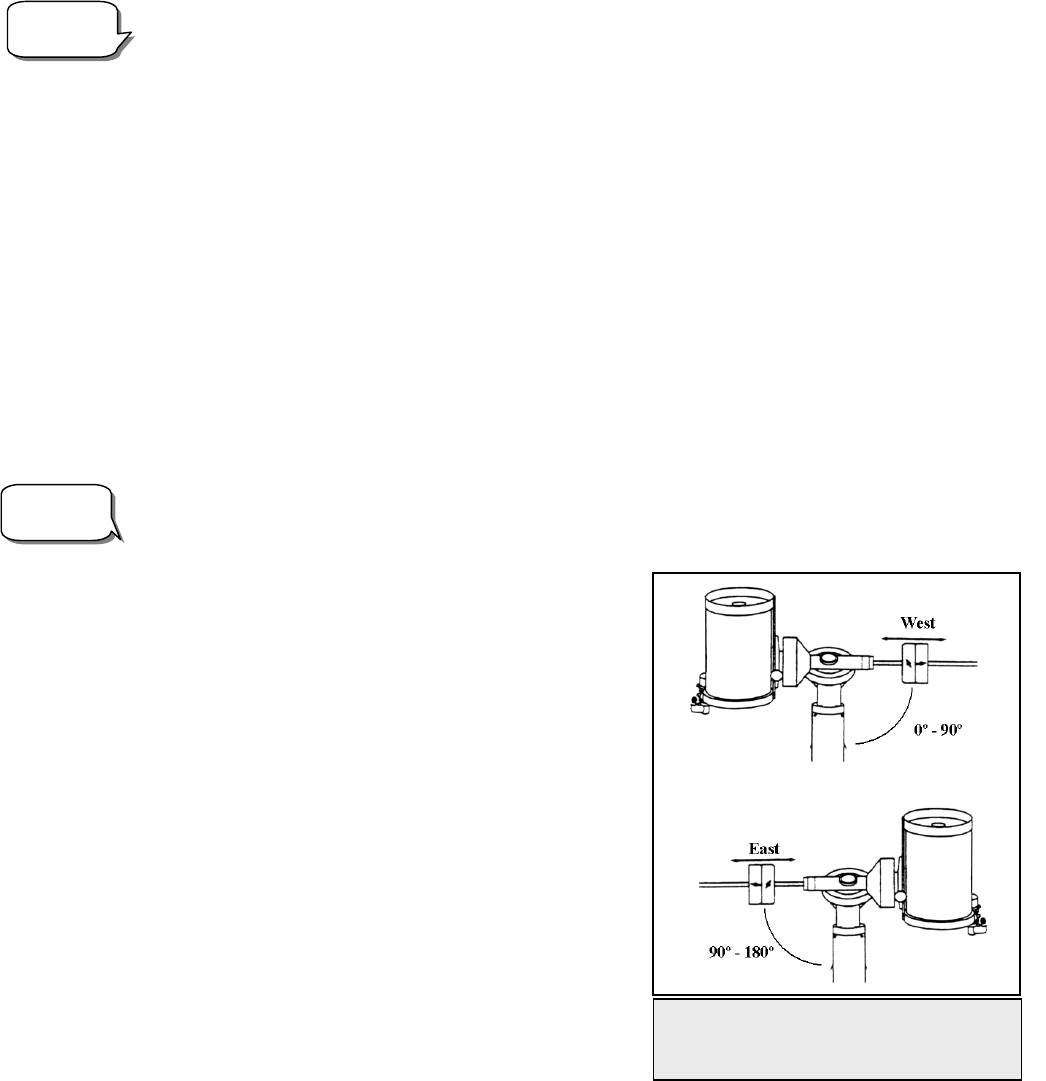
25
example, if you are observing from a mountainous location where the horizon is partially obscured, you can set your
minimum altitude limit to read +20º. This will make sure that the hand control only displays objects that are higher
in altitude than 20º.
If you want to explore the entire object database, set the maximum altitude limit to 90º and the minimum limit to –
90º. This will display every object in the database lists regardless of whether it is visible in the sky from your
location.
Direction Buttons –The direction a star appears to move in the eyepiece changes depending on which side of the
Meridian the telescope tube is on. This can create confusion especially when guiding on a star when doing
astrophotography. To compensate for this, the direction of the drive control keys can be changed. To reverse the
button logic of the hand control, press the MENU button and select Direction Buttons from the Utilities menu. Use
the Up/Down arrow keys (10) to select either the azimuth (right ascension) or altitude (declination) button direction
and press ENTER. Select either positive or negative for both axes and press ENTER to save. Setting the azimuth
button direction to positive will move the telescope in the same direction that the telescope tracks (i.e. towards the
west). Setting the altitude buttons to positive will move the telescope counterclockwise along the DEC axis.
Goto Approach - lets the user define the direction that the telescope will approach when slewing to an object.
This allows the user the ability to minimize the affects of backlash when slewing from object to object. Just like
with Direction Buttons, setting GoTo Approach to positive will make the telescope approach an object from the
same direction as tracking (west) for azimuth and counterclockwise in declination. Declination Goto approach will
only apply while the telescope tube is on one side of the Meridian. Once the tube passes over to the other side of the
Meridian, the Goto approach will need to be reversed.
To change the Goto approach direction, simply choose Goto Approach from the Scope Setup menu, select either
Altitude or Azimuth approach, choose positive or negative and press ENTER.
In order to minimize the affect of gear backlash on pointing accuracy, the settings for Button Direction should
ideally match the settings for GoTo Approach. By default,
using the up and right direction buttons to center alignment
stars will automatically eliminate much of the backlash in
the gears. If you change the Goto approach of your
telescope it is not necessary to change the Button Direction
as well. Simply take notice of the direction the telescope
moves when completing it final goto approach. If the
telescope approaches its alignment star from the west
(negative azimuth) and clockwise (negative altitude) then
make sure that the buttons used to center the alignment
stars also move the telescope in the same directions.
Autoguide Rate – Allows the user to set an autoguide
rate as a percentage of sidereal rate. This is helpful when
calibrating your telescope to a CCD autoguider for long
exposure photography.
Azimuth Limits - Sets the limits that the telescope can
slew in azimuth (R.A.) The slew limits are set to 0º to
180º; with zero being the position of the telescope when the
counterweight bar is extended out towards the west and 180º
being the position when the counterweight bar is extended out
toward the east (see Fig 3-3). However, the slew limits can
be customized depending on your needs. For example, if you are using CCD imaging equipment that has cables
that are not long enough to move with the telescope as it slews across the sky, you can adjust the azimuth slew limit
on the side of the mount that is restricted by the cables. Using the example above, the user could slew the telescope
Observing
Tip!
Helpful
Hint!
Fig 3-3 – Azimuth Slew Limits- This
figure shows the full range of motion
for the R.A.
(
azimuth
)
axis
26
in R.A. (azimuth) until it reaches the point that the cables are extended to their maximum. Then by displaying the
telescopes azimuth in this position (by looking at Get Alt-Az under the Utilities menu) you can determine the
telescopes azimuth at its most extended position. Enter this azimuth reading for either the maximum or minimum
azimuth slew limit to ensure that the telescope will not slew beyond this point.
Warning: In order for the telescope to be able to slew to a star from the direction that minimizes the amount of
backlash in the gears, it may be necessary for the telescope to slew beyond the specified slew limit in order to
approach the star from the correct direction. This can limit your ability to slew to an object by as much as 6º from
the azimuth slew limit set in the hand control. If this proves to be a problem, the direction that the telescope takes
to center an object can be changed. To change the telescopes slewing direction, see Goto Approach under the Scope
Setup menu. In order to guaranty that the telescope will have a full range of motion in R.A. (azimuth), set the
azimuth slew limits to 354 and 186. This will allow the mount to slew without regard to the slew limits.
East/West (E/W) Filtering - In order to ensure the best possible full sky pointing accuracy, the Advanced series
telescopes automatically filters and chooses its initial alignment stars so that the first two alignment stars are located
on one side of the Meridian and the third star is on the opposite side of the Meridian. East/West Filtering allows you
to turn off this automatic filtering feature, allowing the hand control to display all of its alignment stars when doing
a Auto Three Star Align, without regard to the Meridian.
U
Ut
ti
il
li
it
ty
y
F
Fe
ea
at
tu
ur
re
es
s
Scrolling through the MENU (9) options will also provide access to several advanced utility functions within the
Advanced Series telescopes such as; Calibrate Goto, Polar Alignment, Hibernate as well as many others.
Calibrate Goto - Goto Calibration is a useful tool when attaching heavy visual or photographic accessories to the
telescope. Goto Calibration calculates the amount of distance and time it takes for the
mount to complete its final slow goto when slewing to an object. Changing the
balance of the telescope can prolong the time it takes to complete the final slew.
Goto Calibration takes into account any slight imbalances and changes the final goto
distance to compensate.
Home Position – The telescopes "home" position is a user-definable position that is
used to store the telescope when not in use. The home position is useful when storing
the telescope in a permanent observatory facility. By default the Home position is the
same as the index position used when aligning the mount. To set the Home position
for your mount simply use the arrow buttons on the hand control to move the
telescope mount to the desired position. Select the Set option and press Enter.
Polar Align- The Advanced GT has a polar alignment function that will help you
polar align your telescope for increased tracking precision and astrophotography.
After performing an Auto Alignment, the telescope will slew to where Polaris should
be. By using the equatorial head to center Polaris in the eyepiece, the mount will then
be pointed towards the actual North Celestial Pole. Once Polar Align is complete,
you must re-align your telescope again using any of the alignment methods described
earlier. To polar align the mount in the Northern Hemisphere:
1. With the telescope set up and roughly positioned towards Polaris, align the
mount using the Auto Align or Auto Three Star method.
2. Select Polar Align from the Utilities menu and press Enter.
Based on your current alignment, the telescope will slew to where it thinks Polaris
CALIBRATE GOTO
GOTO
SET
HOME POSTION
POLAR ALIGN
KEYPAD OFF
KEYPAD ON
DISPLAY OFF
DISPLAY ON
LIGHT CONTROL
PRESS UNDO
PRESS "0"
FACTORY SETTING
VERSION
GET ALT-AZ
GOTO ATL-AZ
HIBERNATE
TURN ON/OFF GPS
UTILITIES

27
should be. Use the equatorial head latitude and azimuth adjustments to place Polaris in the center of the eyepiece.
Do not use the direction buttons to position Polaris. Once Polaris is centered in the eyepiece press ENTER; the
polar axis should then be pointed towards the North Celestial Pole.
Light Control – This feature allows you to turn off both the red key pad light and LCD display for daytime use to
conserve power and to help preserve your night vision.
Factory Settings – Returns the Advanced GT hand control to its original factory settings. Parameters such as
backlash compensation values, initial date and time, longitude/latitude along with slew and filter limits will be reset.
However, stored parameters such as user defined objects will remain saved even when Factory Settings is selected.
The hand control will ask you to press the "0" key before returning to the factory default setting.
Version - Selecting this option will allow you to see the current version number of the hand control, motor control
and GPS software (if using optional CN-16 GPS accessory). The first set of numbers indicate the hand control
software version. For the motor control, the hand control will display two sets of numbers; the first numbers are for
azimuth and the second set are for altitude. On the second line of the LCD, the GPS and serial bus versions are
displayed.
Get Alt-Az - Displays the relative altitude and azimuth for the current position of the telescope.
Goto Alt-Az - Allows you to enter a specific altitude and azimuth position and slew to it.
Hibernate - Hibernate allows the telescope to be completely powered down and still retain its alignment when
turned back on. This not only saves power, but is ideal for those that have their telescopes permanently mounted or
leave their telescope in one location for long periods of time. To place your telescope in Hibernate mode:
1. Select Hibernate from the Utility Menu.
2. Move the telescope to a desire position and press ENTER.
3. Power off the telescope. Remember to never move your telescope manually while in Hibernate mode.
Once the telescope is powered on again the display will read Wake Up. After pressing Enter you have the option of
scrolling through the time/site information to confirm the current setting. Press ENTER to wake up the telescope.
Pressing UNDO at the Wake Up screen allows you to explore many of the features of the hand control without
waking the telescope up from hibernate mode. To wake up the telescope after UNDO has been pressed, select
Hibernate from the Utility menu and press ENTER. Do not use the direction buttons to move the telescope while in
hibernate mode.
Turn On/Off GPS - If using your Advanced GT telescope with the optional CN-16 GPS accessory (see Optional
Accessories section of the manual), you will need to turn the GPS on the first time you use the accessory. . If you
want to use the telescope's database to find the coordinates of a celestial object for a future or past dates you would
need to turn the GPS off in order to manually enter a time other than the present.
H
He
el
lp
pf
fu
ul
l
H
Hi
in
nt
t
28
EQ NORT
H
EQ SOUTH
OFF
MODE
SIDEREAL
SOLAR
LUNAR
RATE
TRACKING
VIEW TIME-SITE
SETUP TIME-SIT
E
ANTI-BACKLASH
FILTER LIMITS
DIRECTION BUTTONS
GOTO APPROAC
H
AUTOGUIDE RATE
AZIMUTH LIMITS
EAST/WEST FILTERING
SCOPE SETUP
CALIBRATE GOTO
HOME POSITIO
N
POLAR ALIG
N
LIGHT CONTROL
FACTORY SETTING
VERSION
GET ALT-A
Z
GOTO ALT-A
Z
HIBERNATE
TURN ON/OFF GPS
UTILITIES
GOTO SKY OBJ
SAVE SKY OBJ
ENTER RA & DEC
SAVE LAND OB
J
GOTO LAND OBJ
USER OBJECTS
GET RA-DEC
GOTO RA-DEC
SELECT CATALOG
IDENTIFY
GOTO TYPE
PRECISE GOTO
MENU
SET TO INDEX
ENTER TIM
E
DLS/ST
TIME ZONE
ENTER DATE- MM/DD/YY
CENTER STAR 3
CENTER STAR 2
CENTER STAR 1
AUTO ALIGN
CENTER STAR 1
SELECT STAR 1
CENTER STAR 2
SELECT STAR 2
CENTER STAR 3
SELECT STAR 3
AUTO THREE-STAR ALIG N
LAST ALIGNMENT
QUICK-ALIGN
ENTER LONG/LAT
START-UP PROCUDURE
ALIGNMENT
NAMED STAR
NAMED OBJECT
ASTERISM
TOUR
VARIABLE STAR
DOUBLE STAR
CCD OBJECTS
ABELL
IC CATALOG
CALDWELL
MESSIER
NGC
SAO
SOLAR SYSTEM
CONSTELLATION
LIST
ADVANCED GT
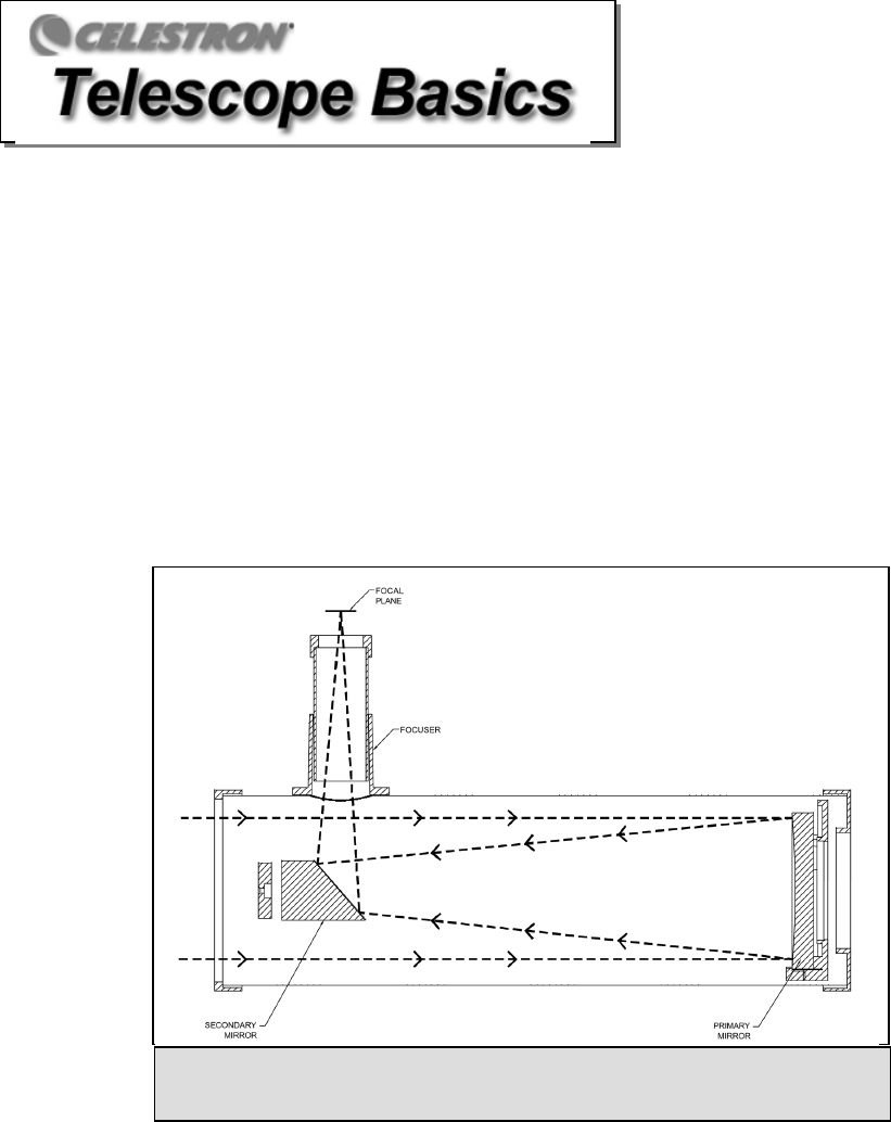
29
A telescope is an instrument that collects and focuses light. The nature of the optical design determines how the light is focused.
Some telescopes, known as refractors, use lenses. Other telescopes, known as reflectors, use mirrors. A Newtonian reflector
uses a single concave mirror as its primary. Light enters the tube traveling to the mirror at the back end. There light
is bent forward in the tube to a single point, its focal point. Since putting your head in front of the telescope to look
at the image with an eyepiece would keep the reflector from working, a flat mirror called a diagonal intercepts the
light and points it out the side of the tube at right angles to the tube. The eyepiece is placed there for easy viewing.
Newtonian Reflector telescopes replace heavy lenses with mirrors to collect and focus the light, providing much
more light-gathering power for the dollar. Because the light path is intercepted and reflected out to the side, you can
have focal lengths up to 1000mm and still enjoy a telescope that is relatively compact and portable. A Newtonian
Reflector telescope offers such impressive light-gathering characteristics you can take a serious interest in deep
space astronomy even on a modest budget. Newtonian Reflector telescopes do require more care and maintenance
because the primary mirror is exposed to air and dust. However, this small drawback does not hamper this type of
telescope’s popularity with those who want an economical telescope that can still resolve faint, distant objects.
I
Im
ma
ag
ge
e
O
Or
ri
ie
en
nt
ta
at
ti
io
on
n
Newtonian reflectors produce a right-side-up image but the image will appear rotated based on the location of the
eyepiece holder in relation to the ground. Newtonian reflectors are best for astronomical use where right-side-up
does not matter.
Figure 4-1
A
A c
cu
ut
ta
aw
wa
ay
y
v
vi
ie
ew
w
o
of
f
t
th
he
e
l
li
ig
gh
ht
t
p
pa
at
th
h
o
of
f
t
th
he
e N
Ne
ew
wt
to
on
ni
ia
an
n
o
op
pt
ti
ic
ca
al
l
d
de
es
si
ig
gn
n
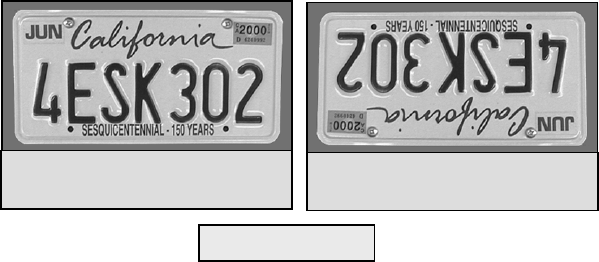
30
Actual image orientation as seen
with the unaided eye
Upside-down image, as viewed
though a Newtonian telescope
F
Fo
oc
cu
us
si
in
ng
g
To focus your telescope, simply turn the focus knob located directly below the eyepiece holder. Turning the knob
clockwise allows you to focus on an object that is farther than the one you are currently observing. Turning the
knob counterclockwise from you allows you to focus on an object closer than the one you are currently observing.
• If you wear corrective lenses (specifically glasses), you may want to remove them when observing with an
eyepiece attached to the telescope. However, when using a camera you should always wear corrective lenses to
ensure the sharpest possible focus. If you have astigmatism, corrective lenses must be worn at all times.
A
Al
li
ig
gn
ni
in
ng
g
t
th
he
e
F
Fi
in
nd
de
er
rs
sc
co
op
pe
e
Accurate alignment of the finder makes it easy to find objects with the telescope, especially celestial objects. To
make aligning the finder as easy as possible, this procedure should be done in the daytime when it is easy to find
and identify objects. The finderscope has a spring-loaded adjustment screw that puts pressure on the finderscope
while the remaining screws are used to adjust the finder horizontally and vertically. To align the finder:
1 Choose a target that is in excess of one mile away. This eliminates any possible parallax effect between the
telescope and finder.
2 Release the R.A. and DEC clamps and point the telescope at your target.
3 Center your target in the main optics of the telescope. You may have to move the telescope slightly to center it.
4 Adjust the screw on the finder bracket that is on the right (when looking through the finder) until the crosshairs are
centered horizontally on the target seen through the telescope.
5 Adjust the screw on the top of the finder bracket until the crosshairs are centered vertically on the target seen
through the telescope.
Image orientation through the finder is inverted (i.e., upside down and backwards left-to-right). This is normal for
any finder that is used straight-through. Because of this, it may take a few minutes to familiarize yourself with the
directional change each screw makes on the finder.
C
Ca
al
lc
cu
ul
la
at
ti
in
ng
g
M
Ma
ag
gn
ni
if
fi
ic
ca
at
ti
io
on
n
You can change the power of your telescope just by changing the eyepiece (ocular). To determine the magnification of your
telescope, simply divide the focal length of the telescope by the focal length of the eyepiece used. In equation format, the
formula looks like this:
Fi
g
ure 4-2
31
Focal Length of Telescope (mm)
Magnification =
Focal Length of Eyepiece (mm)
Let’s say, for example, you are using the 20mm eyepiece. To determine the magnification you simply divide the focal length of
your telescope (the C8-N for example has a focal length of 1000mm) by the focal length of the eyepiece, 20mm. Dividing 1000
by 20 yields a magnification of 50 power.
Although the power is variable, each instrument under average skies has a limit to the highest useful magnification. The general
rule is that 60 power can be used for every inch of aperture. For example, the C8-N is 8 inches in diameter. Multiplying 8 by 60
gives a maximum useful magnification of 480 power. Although this is the maximum useful magnification, most observing is
done in the range of 20 to 35 power for every inch of aperture which is 160 to 280 times for the C8-N telescope.
D
De
et
te
er
rm
mi
in
ni
in
ng
g
F
Fi
ie
el
ld
d
o
of
f
V
Vi
ie
ew
w
Determining the field of view is important if you want to get an idea of the angular size of the object you are observing. To
calculate the actual field of view, divide the apparent field of the eyepiece (supplied by the eyepiece manufacturer) by the
magnification. In equation format, the formula looks like this:
Apparent Field of Eyepiece
True Field =
Magnification
As you can see, before determining the field of view, you must calculate the magnification. Using the example in the previous
section, we can determine the field of view using the same 20mm eyepiece. The 20mm eyepiece has an apparent field of view of
50°. Divide the 50° by the magnification, which is 50 power. This yields an actual field of 1°, or a full degree.
To convert degrees to feet at 1,000 yards, which is more useful for terrestrial observing, simply multiply by 52.5. Continuing
with our example, multiply the angular field 1° by 52.5. This produces a linear field width of 52.5 feet at a distance of one
thousand yards. The apparent field of each eyepiece that Celestron manufactures is found in the Celestron Accessory Catalog
(#93685).
G
Ge
en
ne
er
ra
al
l
O
Ob
bs
se
er
rv
vi
in
ng
g
H
Hi
in
nt
ts
s
When working with any optical instrument, there are a few things to remember to ensure you get the best possible image.
• Never look through window glass. Glass found in household windows is optically imperfect, and as a result, may vary in
thickness from one part of a window to the next. This inconsistency can and will affect the ability to focus your telescope.
In most cases you will not be able to achieve a truly sharp image, while in some cases, you may actually see a double image.
• Never look across or over objects that are producing heat waves. This includes asphalt parking lots on hot summer days or
building rooftops.
• Hazy skies, fog, and mist can also make it difficult to focus when viewing terrestrially. The amount of detail seen under
these conditions is greatly reduced. Also, when photographing under these conditions, the processed film may come out a
little grainier than normal with lower contrast and underexposed.
• If you wear corrective lenses (specifically glasses), you may want to remove them when observing with an eyepiece
attached to the telescope. When using a camera, however, you should always wear corrective lenses to ensure the sharpest
possible focus. If you have astigmatism, corrective lenses must be worn at all times.
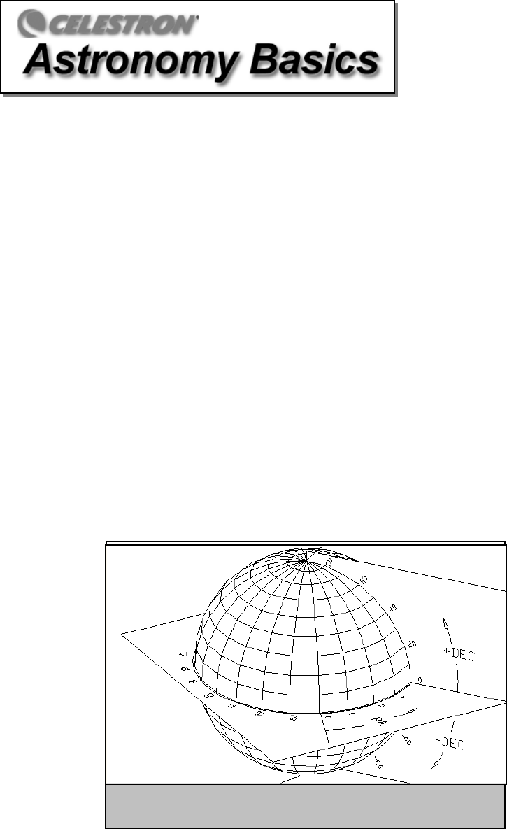
32
Up to this point, this manual covered the assembly and basic operation of your telescope. However, to understand your
telescope more thoroughly, you need to know a little about the night sky. This section deals with observational
astronomy in general and includes information on the night sky and polar alignment.
T
Th
he
e
C
Ce
el
le
es
st
ti
ia
al
l
C
Co
oo
or
rd
di
in
na
at
te
e
S
Sy
ys
st
te
em
m
To help find objects in the sky, astronomers use a celestial coordinate system that is similar to our geographical
coordinate system here on Earth. The celestial coordinate system has poles, lines of longitude and latitude, and an
equator. For the most part, these remain fixed against the background stars.
The celestial equator runs 360 degrees around the Earth and separates the northern celestial hemisphere from the
southern. Like the Earth's equator, it bears a reading of zero degrees. On Earth this would be latitude. However, in the
sky this is referred to as declination, or DEC for short. Lines of declination are named for their angular distance above
and below the celestial equator. The lines are broken down into degrees, minutes of arc, and seconds of arc.
Declination readings south of the equator carry a minus sign (-) in front of the coordinate and those north of the
celestial equator are either blank (i.e., no designation) or preceded by a plus sign (+).
The celestial equivalent of longitude is called Right Ascension, or R.A. for short. Like the Earth's lines of longitude,
they run from pole to pole and are evenly spaced 15 degrees apart. Although the longitude lines are separated by an
angular distance, they are also a measure of time. Each line of longitude is one hour apart from the next. Since the
Earth rotates once every 24 hours, there are 24 lines total. As a result, the R.A. coordinates are marked off in units of
time. It begins with an arbitrary point in the constellation of Pisces designated as 0 hours, 0 minutes, 0 seconds. All
other points are designated by how far (i.e., how long) they lag behind this coordinate after it passes overhead moving
toward the west.
Figure 5-1
The celestial sphere seen from the outside showing R.A. and DEC.
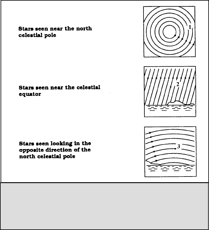
33
M
Mo
ot
ti
io
on
n
o
of
f
t
th
he
e
S
St
ta
ar
rs
s
The daily motion of the Sun across the sky is familiar to even the most casual observer. This daily trek is not the Sun
moving as early astronomers thought, but the result of the Earth's rotation. The Earth's rotation also causes the stars to
do the same, scribing out a large circle as the Earth completes one rotation. The size of the circular path a star follows
depends on where it is in the sky. Stars near the celestial equator form the largest circles rising in the east and setting in
the west. Moving toward the north celestial pole, the point around which the stars in the northern hemisphere appear to
rotate, these circles become smaller. Stars in the mid-celestial latitudes rise in the northeast and set in the northwest.
Stars at high celestial latitudes are always above the horizon, and are said to be circumpolar because they never rise and
never set. You will never see the stars complete one circle because the sunlight during the day washes out the starlight.
However, part of this circular motion of stars in this region of the sky can be seen by setting up a camera on a tripod
and opening the shutter for a couple hours. The processed film will reveal semicircles that revolve around the pole.
(This description of stellar motions also applies to the southern hemisphere except all stars south of the celestial equator
move around the south celestial pole.)
Figure 5-2
All stars appear to rotate around the celestial poles. However, the appearance of this motion
varies depending on where you are looking in the sky. Near the north celestial pole the stars
scribe out recognizable circles centered on the pole (1). Stars near the celestial equator also
follow circular paths around the pole. But, the complete path is interrupted by the horizon.
These appear to rise in the east and set in the west (2). Looking toward the opposite pole, stars
curve or arc in the opposite direction scribing a circle around the opposite pole (3).
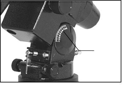
34
Latitude Scales
The easiest way to polar align a telescope is with a latitude scale. Unlike other methods that require you to find the
celestial pole by identifying certain stars near it, this method works off of a known constant to determine how high the
polar axis should be pointed. The Advanced Series mount can be adjusted from 30 to 60 degrees (see figure 5-3).
The constant, mentioned above, is a relationship
between your latitude and the angular distance the
celestial pole is above the northern (or southern)
horizon; The angular distance from the northern
horizon to the north celestial pole is always equal to
your latitude. To illustrate this, imagine that you are
standing on the north pole, latitude +90°. The north
celestial pole, which has a declination of +90°, would
be directly overhead (i.e., 90 above the horizon).
Now, let’s say that you move one degree south — your
latitude is now +89° and the celestial pole is no longer
directly overhead. It has moved one degree closer
toward the northern horizon. This means the pole is
now 89° above the northern horizon. If you move one
degree further south, the same thing happens again.
You would have to travel 70 miles north or south to change your latitude by one degree. As you can see from this
example, the distance from the northern horizon to the celestial pole is always equal to your latitude.
If you are observing from Los Angeles, which has a latitude of 34°, then the celestial pole is 34° above the northern
horizon. All a latitude scale does then is to point the polar axis of the telescope at the right elevation above the northern
(or southern) horizon. To align your telescope:
1. Make sure the polar axis of the mount is pointing due north. Use a landmark that you know faces north.
2. Level the tripod. There is a bubble level built into the mount for this purpose.
NOTE: Leveling the tripod is only necessary if using this method of polar alignment. Perfect polar alignment is still
possible using other methods described later in this manual without leveling the tripod.
3. Adjust the mount in altitude until the latitude indicator points to your latitude. Moving the mount affects the angle the
polar axis is pointing. For specific information on adjusting the equatorial mount, please see the section “Adjusting the
Mount.”
This method can be done in daylight, thus eliminating the need to fumble around in the dark. Although this method
does NOT put you directly on the pole, it will limit the number of corrections you will make when tracking an object.
It will also be accurate enough for short exposure prime focus planetary photography (a couple of seconds) and short
exposure piggyback astrophotography (a couple of minutes).
Pointing at Polaris
This method utilizes Polaris as a guidepost to the celestial pole. Since Polaris is less than a degree from the celestial
pole, you can simply point the polar axis of your telescope at Polaris. Although this is by no means perfect alignment,
it does get you within one degree. Unlike the previous method, this must be done in the dark when Polaris is visible.
1. Set the telescope up so that the polar axis is pointing north.
2. Loosen the DEC clutch knob and move the telescope so that the tube is parallel to the polar axis. When this is done,
the declination setting circle will read +90°. If the declination setting circle is not aligned, move the telescope so that
the tube is parallel to the polar axis.
3. Adjust the mount in altitude and/or azimuth until Polaris is in the field of view of the finder.
4. Center Polaris in the field of the telescope using the fine adjustment controls on the mount.
Figure 5-3
Latitude
Scale
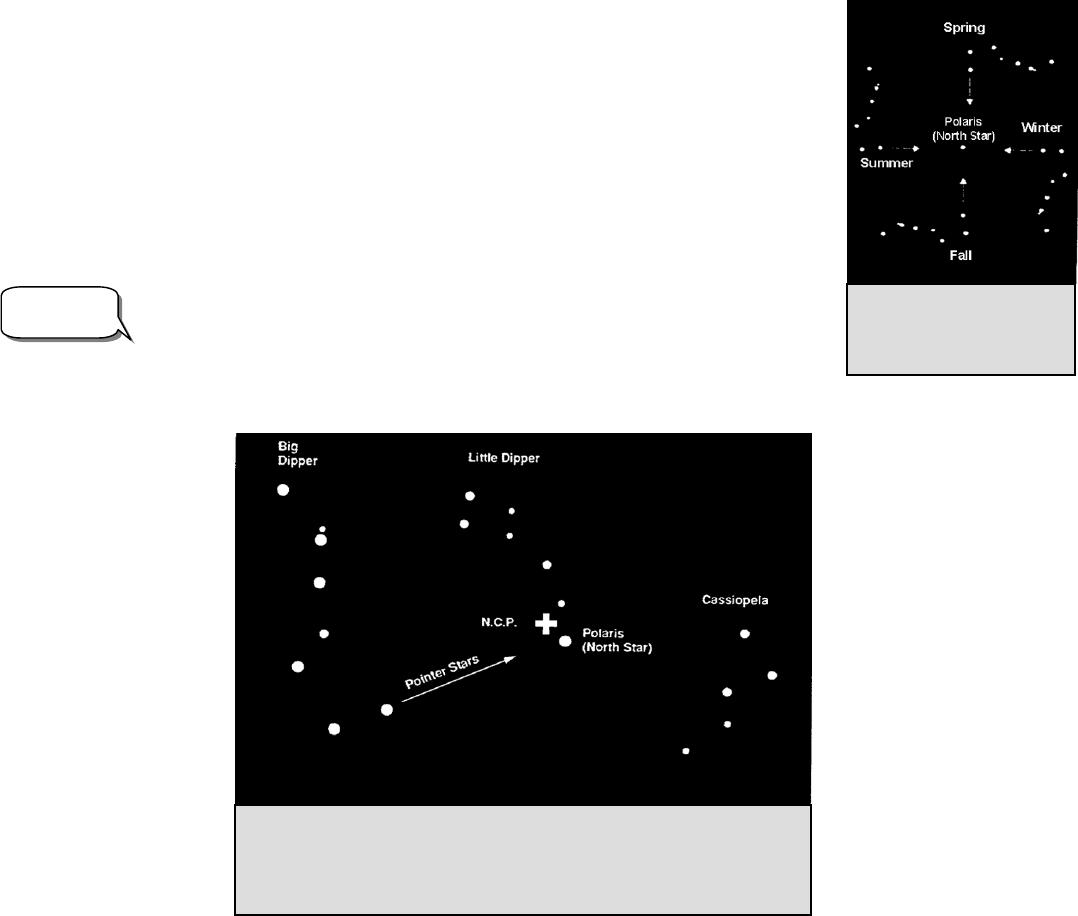
35
Remember, while Polar aligning, do NOT move the telescope in R.A. or DEC. You do not want to move the
telescope itself, but the polar axis. The telescope is used simply to see where the polar axis is pointing.
Like the previous method, this gets you close to the pole but not directly on it. The following methods help improve
your accuracy for more serious observations and photography.
F
Fi
in
nd
di
in
ng
g
t
th
he
e
N
No
or
rt
th
h
C
Ce
el
le
es
st
ti
ia
al
l
P
Po
ol
le
e
In each hemisphere, there is a point in the sky around which all the other stars appear to rotate. These points are called
the celestial poles and are named for the hemisphere in which they reside. For example, in the northern hemisphere all
stars move around the north celestial pole. When the telescope's polar axis is pointed at the celestial pole, it is parallel
to the Earth's rotational axis.
Many methods of polar alignment require that you know how to find the celestial pole by
identifying stars in the area. For those in the northern hemisphere, finding the celestial pole is
not too difficult. Fortunately, we have a naked eye star less than a degree away. This star,
Polaris, is the end star in the handle of the Little Dipper. Since the Little Dipper (technically
called Ursa Minor) is not one of the brightest constellations in the sky, it may be difficult to
locate from urban areas. If this is the case, use the two end stars in the bowl of the Big Dipper
(the pointer stars). Draw an imaginary line through them toward the Little Dipper. They point
to Polaris (see Figure 5-5). The position of the Big Dipper changes during the year and
throughout the course of the night (see Figure 5-4). When the Big Dipper is low in the sky
(i.e., near the horizon), it may be difficult to locate. During these times, look for Cassiopeia
(see Figure 5-5). Observers in the southern hemisphere are not as fortunate as those in the
northern hemisphere. The stars around the south celestial pole are not nearly as bright as those
around the north. The closest star that is relatively bright is Sigma Octantis. This star is just
within naked eye limit (magnitude 5.5) and lies about 59 arc minutes from the pole.
The north celestial pole is the point in the northern hemisphere around which all
stars appear to rotate. The counterpart in the southern hemisphere is referred to as
the south celestial pole.
Definition Figure 5-4 The position of the
Big Dipper changes
throughout the year and the
night.
Figure 5-5
The two stars in the front of the bowl of the Big Dipper point to Polaris which is less
than one degree from the true (north) celestial pole. Cassiopeia, the “W” shaped
constellation, is on the opposite side of the pole from the Big Dipper. The North
Celestial Pole (N.C.P.) is marked by the “+” sign.
36
D
De
ec
cl
li
in
na
at
ti
io
on
n
D
Dr
ri
if
ft
t
M
Me
et
th
ho
od
d
o
of
f
P
Po
ol
la
ar
r
A
Al
li
ig
gn
nm
me
en
nt
t
This method of polar alignment allows you to get the most accurate alignment on the celestial pole and is required if
you want to do long exposure deep-sky astrophotography through the telescope. The declination drift method requires
that you monitor the drift of selected stars. The drift of each star tells you how far away the polar axis is pointing from
the true celestial pole and in what direction. Although declination drift is simple and straight-forward, it requires a
great deal of time and patience to complete when first attempted. The declination drift method should be done after
any one of the previously mentioned methods has been completed.
To perform the declination drift method you need to choose two bright stars. One should be near the eastern horizon
and one due south near the meridian. Both stars should be near the celestial equator (i.e., 0° declination). You will
monitor the drift of each star one at a time and in declination only. While monitoring a star on the meridian, any
misalignment in the east-west direction is revealed. While monitoring a star near the east/west horizon, any
misalignment in the north-south direction is revealed. It is helpful to have an illuminated reticle eyepiece to help you
recognize any drift. For very close alignment, a Barlow lens is also recommended since it increases the magnification
and reveals any drift faster. When looking due south, insert the diagonal so the eyepiece points straight up. Insert the
cross hair eyepiece and align the cross hairs so that one is parallel to the declination axis and the other is parallel to the
right ascension axis. Move your telescope manually in R.A. and DEC to check parallelism.
First, choose your star near where the celestial equator and the meridian meet. The star should be approximately within
1/2 an hour of the meridian and within five degrees of the celestial equator. Center the star in the field of your
telescope and monitor the drift in declination.
• If the star drifts south, the polar axis is too far east.
• If the star drifts north, the polar axis is too far west.
Make the appropriate adjustments to the polar axis to eliminate any drift. Once you have eliminated all the drift, move
to the star near the eastern horizon. The star should be 20 degrees above the horizon and within five degrees of the
celestial equator.
• If the star drifts south, the polar axis is too low.
• If the star drifts north, the polar axis is too high.
Again, make the appropriate adjustments to the polar axis to eliminate any drift. Unfortunately, the latter adjustments
interact with the prior adjustments ever so slightly. So, repeat the process again to improve the accuracy checking both
axes for minimal drift. Once the drift has been eliminated, the telescope is very accurately aligned. You can now do
prime focus deep-sky astrophotography for long periods.
NOTE: If the eastern horizon is blocked, you may choose a star near the western horizon, but you must reverse the
polar high/low error directions. Also, if using this method in the southern hemisphere, the direction of drift is
reversed for both R.A. and DEC.
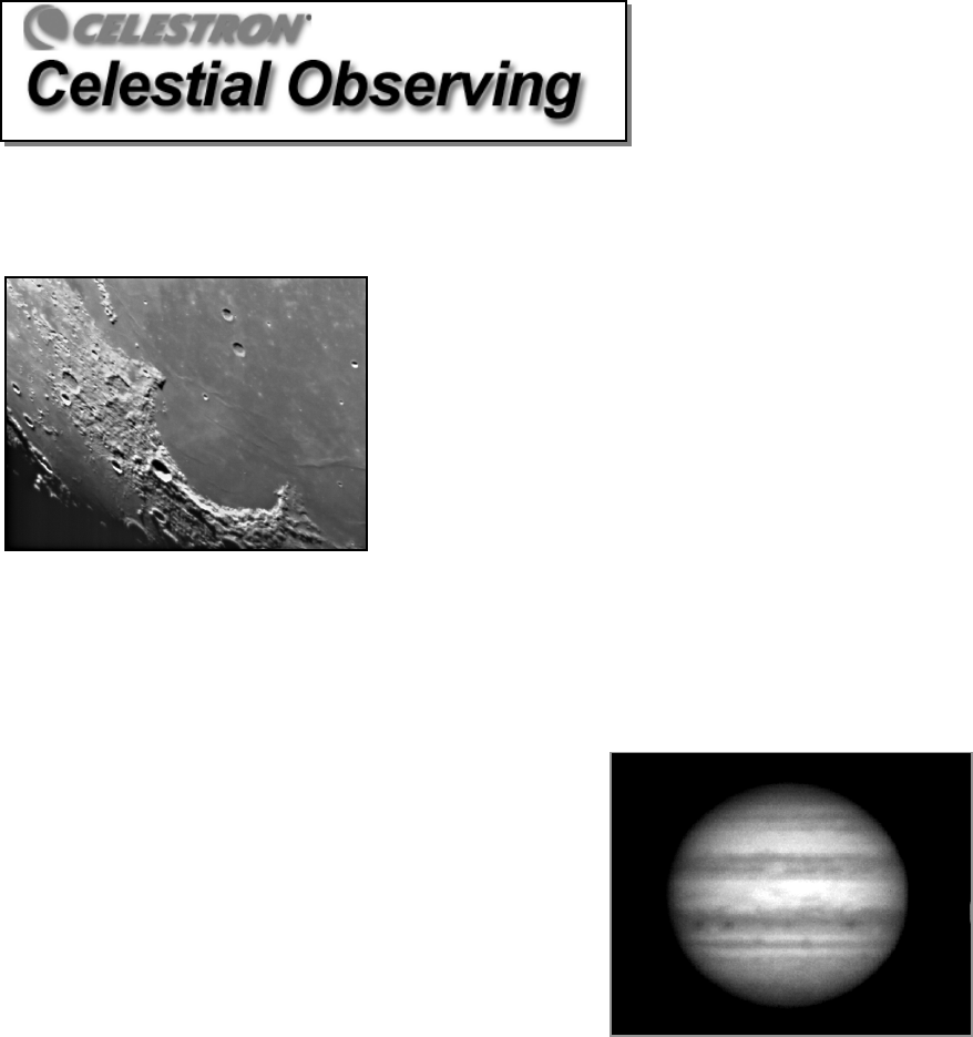
37
With your telescope set up, you are ready to use it for observing. This section covers visual observing hints for both
solar system and deep sky objects as well as general observing conditions which will affect your ability to observe.
O
Ob
bs
se
er
rv
vi
in
ng
g
t
th
he
e
M
Mo
oo
on
n
Often, it is tempting to look at the Moon when it is full. At this time,
the face we see is fully illuminated and its light can be overpowering.
In addition, little or no contrast can be seen during this phase.
One of the best times to observe the Moon is during its partial phases
(around the time of first or third quarter). Long shadows reveal a great
amount of detail on the lunar surface. At low power you will be able to
see most of the lunar disk at one time. Change to higher power
(magnification) to focus in on a smaller area. Choose the lunar tracking
rate from the hand control's MENU tracking rate options to keep the
moon centered in the eyepiece even at high magnifications.
L
Lu
un
na
ar
r
O
Ob
bs
se
er
rv
vi
in
ng
g
H
Hi
in
nt
ts
s
To increase contrast and bring out detail on the lunar surface, use filters. A yellow filter works well at improving
contrast while a neutral density or polarizing filter will reduce overall surface brightness and glare.
O
Ob
bs
se
er
rv
vi
in
ng
g
t
th
he
e
P
Pl
la
an
ne
et
ts
s
Other fascinating targets include the five naked eye planets. You can
see Venus go through its lunar-like phases. Mars can reveal a host of
surface detail and one, if not both, of its polar caps. You will be able to
see the cloud belts of Jupiter and the great Red Spot (if it is visible at
the time you are observing). In addition, you will also be able to see the
moons of Jupiter as they orbit the giant planet. Saturn, with its beautiful
rings, is easily visible at moderate power.
Planetary Observing Hints
• Remember that atmospheric conditions are usually the
limiting factor on how much planetary detail will be visible.
So, avoid observing the planets when they are low on the
horizon or when they are directly over a source of radiating
heat, such as a rooftop or chimney. See the "Seeing Conditions" section later in this section.
• To increase contrast and bring out detail on the planetary surface, try using Celestron eyepiece filters.
O
Ob
bs
se
er
rv
vi
in
ng
g
t
th
he
e
S
Su
un
n
Although overlooked by many amateur astronomers, solar observation is both rewarding and fun. However, because
the Sun is so bright, special precautions must be taken when observing our star so as not to damage your eyes or your
telescope.
Never project an image of the Sun through the telescope. Because of the folded optical design, tremendous heat build-
up will result inside the optical tube. This can damage the telescope and/or any accessories attached to the telescope.
38
For safe solar viewing, use a solar filter that reduces the intensity of the Sun's light, making it safe to view. With a
filter you can see sunspots as they move across the solar disk and faculae, which are bright patches seen near the Sun's
edge.
S
So
ol
la
ar
r
O
Ob
bs
se
er
rv
vi
in
ng
g
H
Hi
in
nt
ts
s
• The best time to observe the Sun is in the early morning or late afternoon when the air is cooler.
• To center the Sun without looking into the eyepiece, watch the shadow of the telescope tube until it forms a
circular shadow.
• To ensure accurate tracking, be sure to select the solar tracking rate.
O
Ob
bs
se
er
rv
vi
in
ng
g
D
De
ee
ep
p
S
Sk
ky
y
O
Ob
bj
je
ec
ct
ts
s
Deep-sky objects are simply those objects outside the boundaries of our solar system. They include star clusters,
planetary nebulae, diffuse nebulae, double stars and other galaxies outside our own Milky Way. Most deep-sky objects
have a large angular size. Therefore, low-to-moderate power is all you need to see them. Visually, they are too faint to
reveal any of the color seen in long exposure photographs. Instead, they appear black and white. And, because of their
low surface brightness, they should be observed from a dark-sky location. Light pollution around large urban areas
washes out most nebulae making them difficult, if not impossible, to observe. Light Pollution Reduction filters help
reduce the background sky brightness, thus increasing contrast.
S
Se
ee
ei
in
ng
g
C
Co
on
nd
di
it
ti
io
on
ns
s
Viewing conditions affect what you can see through your telescope during an observing session. Conditions include
transparency, sky illumination, and seeing. Understanding viewing conditions and the effect they have on observing
will help you get the most out of your telescope.
T
Tr
ra
an
ns
sp
pa
ar
re
en
nc
cy
y
Transparency is the clarity of the atmosphere which is affected by clouds, moisture, and other airborne particles. Thick
cumulus clouds are completely opaque while cirrus can be thin, allowing the light from the brightest stars through.
Hazy skies absorb more light than clear skies making fainter objects harder to see and reducing contrast on brighter
objects. Aerosols ejected into the upper atmosphere from volcanic eruptions also affect transparency. Ideal conditions
are when the night sky is inky black.
S
Sk
ky
y
I
Il
ll
lu
um
mi
in
na
at
ti
io
on
n
General sky brightening caused by the Moon, aurorae, natural airglow, and light pollution greatly affect transparency.
While not a problem for the brighter stars and planets, bright skies reduce the contrast of extended nebulae making
them difficult, if not impossible, to see. To maximize your observing, limit deep sky viewing to moonless nights far
from the light polluted skies found around major urban areas. LPR filters enhance deep sky viewing from light
polluted areas by blocking unwanted light while transmitting light from certain deep sky objects. You can, on the other
hand, observe planets and stars from light polluted areas or when the Moon is out.
S
Se
ee
ei
in
ng
g
Seeing conditions refers to the stability of the atmosphere and directly affects the amount of fine detail seen in extended
objects. The air in our atmosphere acts as a lens which bends and distorts incoming light rays. The amount of bending
depends on air density. Varying temperature layers have different densities and, therefore, bend light differently. Light
rays from the same object arrive slightly displaced creating an imperfect or smeared image. These atmospheric
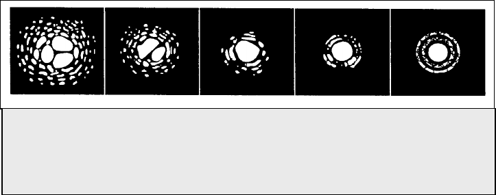
39
disturbances vary from time-to-time and place-to-place. The size of the air parcels compared to your aperture
determines the "seeing" quality. Under good seeing conditions, fine detail is visible on the brighter planets like Jupiter
and Mars, and stars are pinpoint images. Under poor seeing conditions, images are blurred and stars appear as blobs.
The conditions described here apply to both visual and photographic observations.
Figure 6-1
Seeing conditions directly affect image quality. These drawings represent a
point source (i.e., star) under bad seeing conditions (left) to excellent conditions
(right). Most often, seeing conditions produce images that lie some where
between these two extremes.

40
After looking at the night sky for a while you may want to try photographing it. Several forms of photography are
possible with your telescope, including terrestrial and celestial photography. Both of these are discussed in moderate
detail with enough information to get you started. Topics include the accessories required and some simple techniques.
More information is available in some of the publications listed at the end of this manual.
In addition to the specific accessories required for each type of celestial photography, there is the need for a camera -
but not just any camera. The camera does not have to have many of the features offered on today's state-of-the-art
equipment. For example, you don't need auto focus capability or mirror lock up. Here are the mandatory features a
camera needs for celestial photography. First, a “B” setting which allows for time exposures. This excludes point and
shoot cameras and limits the selection to SLR cameras, the most common type of 35mm camera on the market today.
Second, the “B” or manual setting should NOT run off the battery. Many new electronic cameras use the battery to
keep the shutter open during time exposures. Once the batteries are drained, usually after a few minutes, the shutter
closes, whether you were finished with the exposure or not. Look for a camera that has a manual shutter when
operating in the time exposure mode. Olympus, Nikon, Minolta, Pentax, Canon and others have made such camera
bodies.
The camera must have interchangeable lenses so you can attach it to the telescope and so you can use a variety of
lenses for piggyback photography. If you can't find a new camera, you can purchase a used camera body that is not
100-percent functional. The light meter, for example, does not have to be operational since you will be determining the
exposure length manually.
You also need a cable release with a locking function to hold the shutter open while you do other things. Mechanical
and air release models are available.
P
Pi
ig
gg
gy
yb
ba
ac
ck
k
The easiest way to enter the realm of deep-sky, long exposure astrophotography is via the piggyback
method. Piggyback photography is done with a camera and its normal lens riding on top of the telescope.
Through piggyback photography you can capture entire constellations and record large scale nebulae that
are too big for prime focus photography. Because you are photographing with a low power lens and
guiding with a high power telescope, the margin for error is very large. Small mistakes made while guiding
the telescope will not show up on film. To attach the camera to the telescope, use the piggyback adapter
screw located on the top of the tube mounting ring. It may be necessary to remove the finder scope bracket
before attaching the camera
As with any form of deep-sky photography, it should be done from a dark sky observing site. Light
pollution around major urban areas washes out the faint light of deep-sky objects. You can still practice
from less ideal skies.
1. Polar align the telescope (using one of the methods described earlier) and start the motor drive.
2. Load your camera with slide film, ISO 100 or faster, or print film, ISO 400 or faster!
3. Set the f/ratio of your camera lens so that it is a half stop to one full stop down from completely open.
4. Set the shutter speed to the “B” setting and focus the lens to the infinity setting.
5. Locate the area of the sky that you want to photograph and move the telescope so that it points in that
direction.
41
6. Find a suitable guide star in the telescope eyepiece field of view. This is relatively easy since you can
search a wide area without affecting the area covered by your camera lens. If you do not have an
illuminated cross hair eyepiece for guiding, simply defocus your guide star until it fills most of the field of
view. This makes it easy to detect any drift.
7. Release the shutter using a cable release.
8. Monitor your guide star for the duration of the exposure making the neccessary corrections needed to keep
the star centered.
S
Sh
ho
or
rt
t
E
Ex
xp
po
os
su
ur
re
e
P
Pr
ri
im
me
e
F
Fo
oc
cu
us
s
P
Ph
ho
ot
to
og
gr
ra
ap
ph
hy
y
Short exposure prime focus photography is the best way to begin recording celestial objects. It is done with
the camera attached to the telescope without an eyepiece or camera lens in place. To attach your camera,
you need the T-adapter and a T-Ring for your specific camera (i.e., Minolta, Nikon, Pentax, etc.). The
C8-N and C10-N focuser have a built-in T-adapter and are ready to accept a 35mm camera body. The T-
Ring replaces the 35mm SLR camera’s normal lens. Prime focus photography allows you to capture the
entire solar disk (if using the proper filter) as well as the entire lunar disk. To attach your camera to your
telescope:
1 Remove the eyepiece from the 1 1/4
" eyepiece holder.
2 Unthread the 1 1/4
" eyepiece holder from the focuser assembly. This will expose the male thread of the built-
in T-adapter.
3 Thread the T-ring onto the exposed T-adapter threads.
4 Mount your camera body onto the T-Ring the same as you would any other lens.
With your camera attached to the telescope, you are ready for prime focus photography. Start with an easy
object like the Moon. Here’s how to do it:
1. Load your camera with film that has a moderate-to-fast speed (i.e., ISO rating). Faster films are more
desirable when the Moon is a crescent. When the Moon is near full, and at its brightest, slower films are
more desirable. Here are some film recommendations:
• T-Max 100
• T-Max 400
• Any 100 to 400 ISO color slide film
• Fuji Super HG 400
2. Center the Moon in the field of your telescope.
3. Focus the telescope by turning the focus knob until the image is sharp.
4. Set the shutter speed to the appropriate setting (see table 7-1).
5. Trip the shutter using a cable release.
6. Advance the film and repeat the process.

42
Lunar Phase ISO 50 ISO 100 ISO 200 ISO 400
Crescent 1/2 1/4 1/8 1/15
Quarter 1/15 1/30 1/60 1/125
Full 1/30 1/60 1/125 1/250
The exposure times listed in table 7-1 should be used as a starting point. Always make exposures that are longer and
shorter than the recommended time. Also, take a few photos at each shutter speed. This will ensure that you will get a
good photo.
• If using black and white film, try a yellow filter to reduce the light intensity and to increase contrast.
• Keep accurate records of your exposures. This information is useful if you want to repeat your results or
if you want to submit some of your photos to various astronomy magazines for possible publication!
• This technique is also used for photographing the Sun with the proper solar filter.
T
Te
er
rr
re
es
st
tr
ri
ia
al
l
P
Ph
ho
ot
to
og
gr
ra
ap
ph
hy
y
Your telescope makes an excellent telephoto lens for terrestrial (land) photography. Terrestrial photography is best
done will the telescope tracking drive turned off. To turn the tracking drive off, press the MENU (9) button on the
hand control and scroll down to the Tracking Mode sub menu. Use the Up and Down scroll keys (10) to select the Off
option and press ENTER. This will turn the tracking motors off, so that objects will remain in your camera's field of
view.
M
Me
et
te
er
ri
in
ng
g
The Advanced Series telescope has a fixed aperture and, as a result, fixed f/ratios. To properly expose your subjects
photographically, you need to set your shutter speed accordingly. Most 35mm SLR cameras offer through-the-lens
metering which lets you know if your picture is under or overexposed. Adjustments for proper exposures are made by
changing the shutter speed. Consult your camera manual for specific information on metering and changing shutter
speeds.
R
Re
ed
du
uc
ci
in
ng
g
V
Vi
ib
br
ra
at
ti
io
on
n
Releasing the shutter manually can cause vibrations, producing blurred photos. To reduce vibration when tripping the
shutter, use a cable release. A cable release keeps your hands clear of the camera and lens, thus eliminating the
possibility of introducing vibration. Mechanical shutter releases can be used, though air-type releases are best.
Blurry pictures can also result from shutter speeds that are too slow. To prevent this, use films that produce shutter
speeds greater than 1/250 of a second when hand-holding the lens. If the lens is mounted on a tripod, the exposure
length is virtually unlimited.
Another way to reduce vibration is with the Vibration Suppression Pads (#93503). These pads rest between the
ground and tripod feet. They reduce the vibration amplitude and vibration time.
Table 7-1
Above is a listing of recommended exposure times when photographing the Moon at the
p
rime focus of
y
our telesco
p
e.
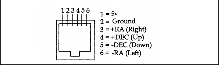
43
A
Au
ut
to
o
G
Gu
ui
id
di
in
ng
g
The Advanced GT telescope has a designated auto guiding port for use with a CCD autoguider. The
diagram below may be useful when connecting the CCD camera cable to the telescope and calibrating the
autoguider. Note that the four outputs are active-low, with internal pull-ups and are capable of sinking 25
mA DC.
44
While your telescope requires little maintenance, there are a few things to remember that will ensure your telescope performs at
its best.
C
Ca
ar
re
e
a
an
nd
d
C
Cl
le
ea
an
ni
in
ng
g
o
of
f
t
th
he
e
O
Op
pt
ti
ic
cs
s
Occasionally, dust and/or moisture may build up on the mirrors of your telescope. Special care should be taken when cleaning
any instrument so as not to damage the optics.
If dust has built up on the mirror, remove it with a brush (made of camel’s hair) or a can of pressurized air. Spray at an angle to
the mirror for approximately two to four seconds. Then, use an optical cleaning solution and white tissue paper to remove any
remaining debris. Apply the solution to the tissue and then apply the tissue paper to the mirror. Low pressure strokes should go
from the center of the mirror to the outer portion. Do NOT rub in circles!
You can use a commercially made lens cleaner or mix your own. A good cleaning solution is isopropyl alcohol mixed with
distilled water. The solution should be 60% isopropyl alcohol and 40% distilled water. Or, liquid dish soap diluted with water (a
couple of drops per one quart of water) can be used.
To minimize the need to clean your telescope, replace all lens covers once you have finished using it. Since the telescope tube is
NOT sealed, the cover should be placed over the opening when not in use. This will prevent contaminants from entering the
optical tube.
C
Co
ol
ll
li
im
ma
at
ti
io
on
n
The optical performance of most Newtonian reflecting telescopes can be optimized by re-collimating (aligning) the
telescope's optics, as needed. To collimate the telescope simply means to bring its optical elements into balance.
Poor collimation will result in optical aberrations and distortions.
Before collimating your telescope, take time to familiarize yourself with all its components. The primary mirror is
the large mirror at the back end of the telescope tube. This mirror is adjusted by loosening and tightening the three
screws, placed 120 degrees apart, at the end of the telescope tube. The secondary mirror (the small, elliptical mirror
under the focuser, in the front of the tube) also has three adjustment screws. To determine if your telescope needs
collimation first point your telescope toward a bright wall or blue sky outside.
Never look directly at the sun with the naked eye or with a telescope (unless you have the proper solar filter).
Permanent and irreversible eye damage may result.
Aligning the Secondary Mirror
The following describes the procedure for daytime collimation of your telescope using the optional Newtonian
Collimation Tool (#94183) offered by Celestron. To collimate the telescope without the Collimation Tool, read the
following section on night time star collimation.
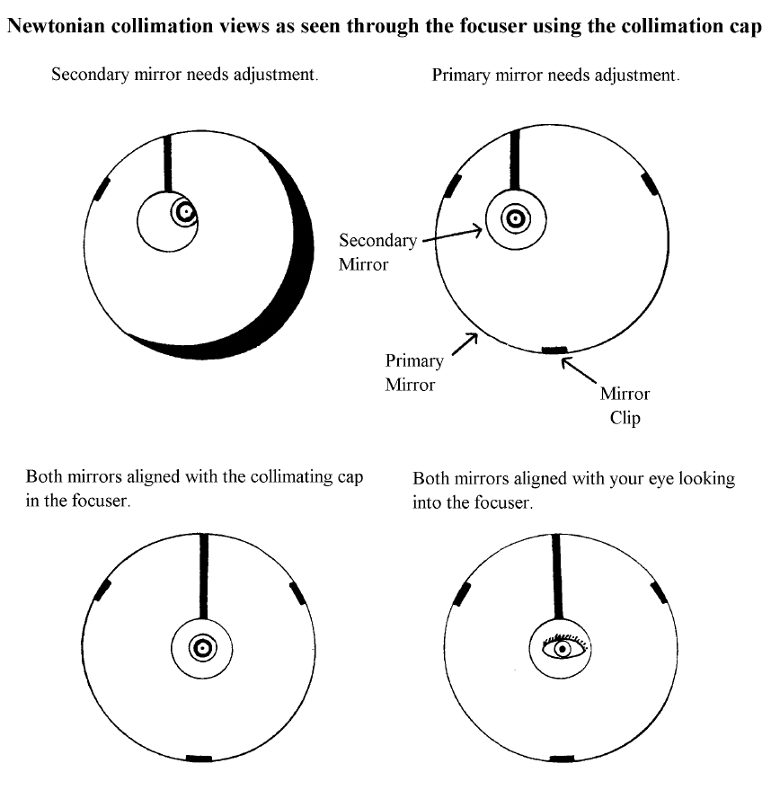
45
If you have an eyepiece in the focuser, remove it. Rack the focuser tube in completely, using the focusing knobs,
until its silver tube is no longer visible. You will be looking through the focuser at a reflection of the secondary
mirror, projected from the primary mirror. During this step, ignore the silhouetted reflection from the primary
mirror. Insert the collimating cap into the focuser and look through it. With the focus pulled in all the way, you
should be able to see the entire primary mirror reflected in the secondary mirror. If the primary mirror is not
centered in the secondary mirror, adjust the secondary mirror screws by alternately tightening and loosening them
until the periphery of the primary mirror is centered in your view. DO NOT loosen or tighten the center screw in the
secondary mirror support, because it maintains proper mirror position.
Aligning the Primary Mirror
Now adjust the primary mirror screws to re-center the reflection of the small secondary mirror, so it’s silhouetted
against the view of the primary. As you look into the focuser, silhouettes of the mirrors should look concentric.
Repeat steps one and two until you have achieved this.
Remove the collimating cap and look into the focuser, where you should see the reflection of your eye in the
secondary mirror.
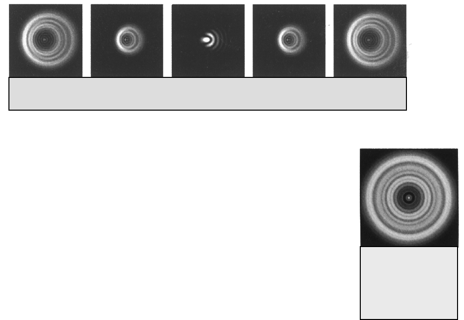
46
Figure 8-2
A collimated telescope
should appear as a
symmetrical ring pattern
similar to the diffraction
disk seen here.
Night Time Star Collimating
After successfully completing daytime collimation, night time star collimation can be done by closely adjusting the
primary mirror while the telescope tube is on its mount and pointing at a bright star. The telescope should be set up
at night and a star's image should be studied at medium to high power (30-60 power per inch of aperture). If a non-
symmetrical focus pattern is present, then it may be possible to correct this by re-collimating only the primary
mirror.
Procedure
(Please read this section completely before beginning)
To star collimate in the Northern Hemisphere, point at a stationary star like the North Star (Polaris). It can be found
in the north sky, at a distance above the horizon equal to your latitude. It’s also the end star in the handle of the Little
Dipper. Polaris is not the brightest star in the sky and may even appear dim, depending upon your sky conditions.
Prior to re-collimating the primary mirror, locate the collimation screws on the end of the telescope tube. These three
screws are to be adjusted one at a time. Normally, motions on the order of an 1/8 turn will make a difference, with
approximately a 1/2 to 3/4 turn being the maximum required.
With Polaris or a bright star centered within the field of view, focus with either the standard ocular or your highest
power ocular, i.e. the shortest focal length in mm, such as a 6mm or 4mm. Another option is to use a longer focal
length ocular with a Barlow lens. When a star is in focus it should look like a sharp pinpoint of light. If, when
focusing on the star, it is irregular in shape or appears to have a flare of light at its edge, this means your mirrors
aren’t in alignment. If you notice the appearance of a flare of light from the star that remains stable in location, just
as you go in and out of exact focus, then re-collimation will help sharpen the image.
Take note of the direction the light appears to flare. For example, if it appears to flare toward the three o'clock
position in the field of view, then you must move whichever screw or combination of collimation screws necessary
to move the star’s image toward the direction of the flaring. In this example, you
would want to move the image of the star in your eyepiece, by adjusting the
collimation screws, toward the three o'clock position in the field of view. It may only
be necessary to adjust a screw enough to move the star’s image from the center of the
field of view to about halfway, or less, toward the field's edge (when using a high
power ocular).
Collimation adjustments are best made while viewing the star's position in the field of
view and turning the adjustment screws simultaneously. This way, you can see exactly
which way the movement occurs. It may be helpful to have two people working
together: one viewing and instructing which screws to turn and by how much, and the
other performing the adjustments.
Fig 8-1 Even though the star pattern appears the same on both sides of focus, they are asymmetric. The dark
obstruction is skewed off to the left side of the diffraction pattern indicating poor collimation.
47
IMPORTANT: After making the first, or each adjustment, it is necessary to re-aim the telescope tube to re-center
the star again in the center of the field of view. The star image can then be judged for symmetry by going just inside
and outside of exact focus and noting the star's pattern. Improvement should be seen if the proper adjustments are
made. Since three screws are present, it may be necessary to move at least two of them to achieve the necessary
mirror movement.
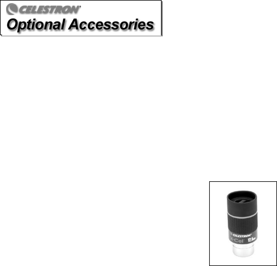
48
You will find that additional accessories enhance your viewing pleasure and expand the usefulness of your
telescope. For ease of reference, all the accessories are listed in alphabetical order.
Adapter AC (#18773) - Allow DC (battery powered) telescopes to be converted for use with 120 volt AC power.
Auxiliary Port Accessory (#93965) – This accessory plugs into the auxiliary port of the telescopes control panel to
provide additional ports for accessories like the CN-16 GPS as well as a PC programming port.
Barlow Lens - A Barlow lens is a negative lens that increases the focal length of a telescope. Used with any eyepiece, it
doubles the magnification of that eyepiece. Celestron offers two Barlow lens in the 1-1/4" size. The 2x Ultima Barlow
(#93506) is a compact triplet design that is fully multicoated for maximum light transmission and parfocal when used with
the Ultima eyepieces. The OMNI Barlow (#93326) is a compact achromatic Barlow lens that is under three inches long and
weighs only 4 oz. It works very well with all Celestron eyepieces.
Eyepieces - Like telescopes, eyepieces come in a variety of designs. Each design has its own advantages and
disadvantages. For the 1-1/4" barrel diameter there are four different eyepiece designs available.
• OMNI Plössl - Plössl eyepieces have a 4-element lens designed for low-to-high power observing. The Plössls offer
razor sharp views across the entire field, even at the edges! In the 1-1/4" barrel diameter, they are available in the
following focal lengths: 4mm, 6mm, 9mm, 12.5mm, 15mm, 20mm, 25mm, 32mm and
40mm.
• X-Cel - This 6 element design allows each X-Cel Eyepiece to have 20mm of eye relief, 55°
field of view and more than 25mm of lens aperture (even with the 2.3mm). In order to
maintain razor sharp, color corrected images across its 55° field of view, extra-low
dispersion glass is used for the most highly curved optical elements. The excellent refractive
properties of these high grade optical elements, make the X-Cel line especially well suited
for high magnification planetary viewing where sharp, color-free views are most
appreciated. X-Cel eyepiece come in the following focal lengths: 2.3mm, 5mm, 8mm,
10mm, 12.5mm, 18mm, 21mm, 25mm.
• Ultima - Ultima is our 5-element, wide field eyepiece design. In the 1-1/4" barrel diameter,
they are available in the following focal lengths: 5mm, 7.5mm, 10mm, 12.5mm, 18mm,
30mm, 35mm, and 42mm. These eyepieces are all parfocal. The 35mm Ultima gives the
widest possible field of view with a 1-1/4" diagonal.
• Axiom – As an extension of the Ultima line, a new wide angle series is offered – called the Axiom series. All units are
seven element designs and feature a 70º extra wide field of view (except the 50mm). All are fully multicoated and
contain all the features of the Ultimas.
Filters Sets, Eyepiece - Celestron offers four convenient filter sets, which contain four different filters per set. Not only
are these highly useful filter combinations, but they also offer an economical way to add versatility to your filter collection.
Series 1 – #94119-10
Orange, Light Blue, ND13%T, Polarizing (#s 21, 80A, #15, Polarizing)
Series 2 – #94119-20
Deep Yellow, Red, Light Green, ND25% T (#s 12, 25, 56, 96ND-25)
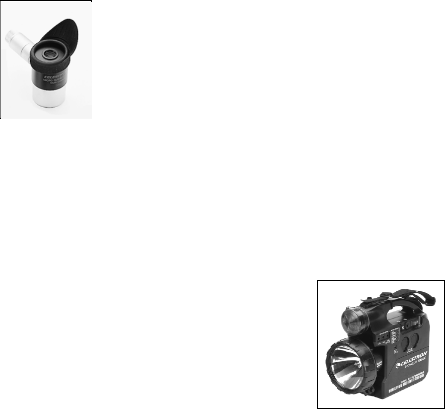
49
Series 3 – #94119-30
Light Red, Blue, Green, ND50% T (#s 23A, 38A, 58, 96ND-50)
Series 4 – #94119-40
Yellow, Deep Yellow, Violet, Pale Blue (#s 8, 47, 82A, 96ND-13)
Flashlight, Night Vision - (#93588) - Celestron’s premium model for astronomy, using two red LED's to preserve night
vision better than red filters or other devices. Brightness is adjustable. Operates on a single 9 volt battery (included).
CN16 GPS Accessory (#93963) - Plug in this 16-channel GPS module into your telescopes drive base port to link up and
automatically download information from one of many global positioning satellites. Controlled with the computerized hand
control, the CN-16 will greatly improve the accuracy of your star alignments.
CN16 GPS Bracket (#93964) – Support your CN-16 GPS accessory with this bracket and strap combination that securely
wraps around any of the tripod legs and holds the GPS module in place .
Light Pollution Reduction (LPR) Filters (#94126A) - These filters are designed to enhance your views of deep sky
astronomical objects when viewed from urban areas. LPR Filters selectively reduce the transmission of certain wavelengths
of light, specifically those produced by artificial lights. This includes mercury and high and low pressure sodium vapor
lights. In addition, they also block unwanted natural light (sky glow) caused by neutral oxygen
emission in our atmosphere.
Micro Guide Eyepiece (#94171) - This multipurpose 12.5mm illuminated reticle can be used for
guiding deep-sky astrophotos, measuring position angles, angular separations, and more. The
laser etched reticle provides razor sharp lines and the variable brightness illuminator is
completely cordless. The micro guide eyepiece produces 80 power with the C8-N and 96 power
with the C10-N.
Moon Filter (#94119-A) - Celestron’s Moon Filter is an economical eyepiece filter for reducing
the brightness of the moon and improving contrast, so greater detail can be observed on the lunar
surface. The clear aperture is 21mm and the transmission is about 18%.
Motor Drive, Single Axis (#93518) — This motor drive is a single axis (R.A.), DC motor drive. It is powered by four D-
cell batteries (not included). 2x and 4x sidereal speeds are available through the included hand controller. For non-
computerized Advanced Series Mounts.
Motor Drive, Dual Axis (#93523) - This dual axis motor drive, with drive corrector capabilities, are designed for
Celestron's Advanced CG-5 mounts. They precisely control the telescope's tracking speed during long, timed exposures of
celestial objects, producing the best possible image sharpness. Four speeds are available—1x (sidereal), 2x for guiding, 4x,
and 8x for centering. These precision, state-of-the-art DC motor drives operate from 4 D-cell batteries (not included). The
hand controller module is very compact and fits easily in the palm of your hand. Motors for both axes are included, along
with brackets, clutches and hardware. For non-computerized Advanced Series Mounts.
Polarizing Filter Set (#93608) - The polarizing filter set limits the transmission of light to a specific plane, thus increasing
contrast between various objects. This is used primarily for terrestrial, lunar and planetary observing.
Polar Axis Finderscope (#94220) – This useful accessory speeds accurate polar
alignment by providing a means of visually aligning your German equatorial mount
with Polaris and true north. As a result, you can spend more time observing and less
time setting up. The finderscope has an easy to use cross hair reticle.
PowerTank (#18774) – 12v 7Amp hour rechargeable power supply. Comes with
two 12v output cigarette outlets, built-in red flash light , Halogen emergency
spotlight. Switchable 110v/220v AC adapter and cigarette lighter adapter included.
50
RS-232 Cable (#93920) – Allows your Advanced Series telescope to be controlled using a laptop computer or PC. Once
connected, the telescope can be controlled using popular astronomy software programs.
Sky Maps (#93722) - Celestron Sky Maps are the ideal teaching guide for learning the night sky. You wouldn’t set off on a
road trip without a road map, and you don’t need to try to navigate the night sky without a map either. Even if you already
know your way around the major constellations, these maps can help you locate all kinds of fascinating objects.
T-Ring - The T-Ring couples your 35mm SLR camera body to the T-Adapter, radial guider, or tele-extender. This
accessory is mandatory if you want to do photography through the telescope. Each camera make (i.e., Minolta, Nikon,
Pentax, etc.) has its own unique mount and therefore, its own T-Ring. Celestron has 8 different models for 35mm cameras.
A full description of all Celestron accessories can be found in the Celestron Accessory Catalog (#93685)

51
Appendix A – Technical Specifications
Advanced Series 31061 / 31062 11047 / 11048
C8-N C10-N
Specifications:
Optical Design 200mm (8.0") reflector 254mm (10") reflector
Focal Length 1000mm F/5 Parabola 1200mm F/4.7 Parabola
Finderscope 9x50 9x50
Mount CG-5 Equatorial CG-5 Equatorial
Eyepiece 20mm - 1.25" (50x) 20mm – 1.25" (60x)
Accessory tray Yes Yes
Tripod 2" Stainless Steel 2" Stainless Steel
Technical Specs
Highest Useful Magnification 480x 600x
Lowest Useful Magnification 29x 36x
Limiting Stellar Magnitude 14 14.5
Resolution: Rayleigh .69 arc seconds .54 arc seconds
Dawes Limit .58 arc seconds .46 arc seconds
Photographic Resolution 400 line/mm 425 line/mm
Light Gathering Power 843x unaided eye 1316x unaided eye
Field of View: standard eyepiece 1º .83º
Linear FOV (@1000 yds) 52.5 ft. 43.8 ft.
Optical Coatings - Standard Aluminum Coating Aluminum Coating
Secondary Mirror Obstruction 2.2" 2.3"
by Area 8% 5%
by Diameter 28% 23%
Optical tube length 37 inches 45 inches
Telescope Weight 78 lbs 93 lbs
Advanced GT
Additional Specifications
Hand Control Double line, 16 character Liquid Crystal Display; 19 fiber optic backlit LED buttons
Motor: Type DC Servo motors with encoders, both axes
Max Slew Speed 3º/second
Software Precision 24bit, 0.08 arc sec calculation
Hand Control Ports RS-232 communication port on hand control
Motor Ports Aux Port, Autoguide Ports
Tracking Rates Sidereal, Solar and Lunar
Tracking Modes EQ North & EQ South
Alignment Procedures AutoAlign, 3-Star Alignment, Quick Align, Last Align
Database
40,000+ objects, 400 user defined programmable objects.
Enhanced information on over 200 objects
Complete Revised NGC Catalog 7,840
Complete Messier Catalog 110
Complete IC Catalog 5,386
Complete Caldwell 109
Abell Galaxies 2,712
Solar System objects 9
Famous Asterisms 20
Selected CCD Imaging Objects 25
Selected SAO Stars 29,500
Total Object Database 45,492
52
Appendix B - Glossary of Terms
A-
Absolute magnitude The apparent magnitude that a star would have if it were observed from a standard distance of 10
parsecs, or 32.6 light-years. The absolute magnitude of the Sun is 4.8. at a distance of 10 parsecs, it
would just be visible on Earth on a clear moonless night away from surface light.
Airy disk The apparent size of a star's disk produced even by a perfect optical system. Since the star can never
be focused perfectly, 84 per cent of the light will concentrate into a single disk, and 16 per cent into
a system of surrounding rings.
Alt-Azimuth Mounting A telescope mounting using two independent rotation axis allowing movement of the instrument in
Altitude and Azimuth.
Altitude In astronomy, the altitude of a celestial object is its Angular Distance above or below the celestial
horizon.
Aperture the diameter of a telescope's primary lens or mirror; the larger the aperture, the greater the
telescope's light-gathering power.
Apparent Magnitude A measure of the relative brightness of a star or other celestial object as perceived by an observer on
Earth.
Arcminute A unit of angular size equal to 1/60 of a degree.
Arcsecond A unit of angular size equal to 1/3,600 of a degree (or 1/60 of an arcminute).
Asterism A small unofficial grouping of stars in the night sky.
Asteroid A small, rocky body that orbits a star.
Astrology The pseudoscientific belief that the positions of stars and planets exert an influence on human
affairs; astrology has nothing in common with astronomy.
Astronomical unit (AU) The distance between the Earth and the Sun. It is equal to 149,597,900 km., usually rounded off to
150,000,000 km.
Aurora The emission of light when charged particles from the solar wind slams into and excites atoms and
molecules in a planet's upper atmosphere.
Azimuth The angular distance of an object eastwards along the horizon, measured from due north, between
the astronomical meridian (the vertical line passing through the center of the sky and the north and
south points on the horizon) and the vertical line containing the celestial body whose position is to
be measured. .
B -
Binary Stars Binary (Double) stars are pairs of stars that, because of their mutual gravitational attraction, orbit
around a common Center of Mass. If a group of three or more stars revolve around one another, it
is called a multiple system. It is believed that approximately 50 percent of all stars belong to binary
or multiple systems. Systems with individual components that can be seen separately by a telescope
are called visual binaries or visual multiples. The nearest "star" to our solar system, Alpha Centauri,
is actually our nearest example of a multiple star system, it consists of three stars, two very similar
to our Sun and one dim, small, red star orbiting around one another.
C -
Celestial Equator The projection of the Earth's equator on to the celestial sphere. It divides the sky into two equal
hemispheres.
Celestial pole The imaginary projection of Earth's rotational axis north or south pole onto the celestial sphere.
Celestial Sphere An imaginary sphere surrounding the Earth, concentric with the Earth's center.
Collimation The act of putting a telescope's optics into perfect alignment.
D -
Declination (DEC) The angular distance of a celestial body north or south of the celestial equator. It may be said to
correspond to latitude on the surface of the Earth.
E -
Ecliptic The projection of the Earth's orbit on to the celestial sphere. It may also be defined as "the apparent
yearly path of the Sun against the stars".
Equatorial mount A telescope mounting in which the instrument is set upon an axis which is parallel to the axis of the
Earth; the angle of the axis must be equal to the observer's latitude.
F -
Focal length The distance between a lens (or mirror) and the point at which the image of an object at infinity is
brought to focus. The focal length divided by the aperture of the mirror or lens is termed the focal
ratio.
53
J -
Jovian Planets Any of the four gas giant planets that are at a greater distance form the sun than the terrestrial
planets.
K -
Kuiper Belt A region beyond the orbit of Neptune extending to about 1000 AU which is a source of many short
period comets.
L -
Light-Year (LY) A light-year is the distance light traverses in a vacuum in one year at the speed of 299,792 km/ sec.
With 31,557,600 seconds in a year, the light-year equals a distance of 9.46 X 1 trillion km (5.87 X 1
trillion mi).
M -
Magnitude Magnitude is a measure of the brightness of a celestial body. The brightest stars are assigned
magnitude 1 and those increasingly fainter from 2 down to magnitude 5. The faintest star that can be
seen without a telescope is about magnitude 6. Each magnitude step corresponds to a ratio of 2.5 in
b
rightness. Thus a star of magnitude 1 is 2.5 times brighter than a star of magnitude 2, and 100 times
brighter than a magnitude 5 star. The brightest star, Sirius, has an apparent magnitude of -1.6, the
full moon is -12.7, and the Sun's brightness, expressed on a magnitude scale, is -26.78. The zero
point of the apparent magnitude scale is arbitrary.
Meridian A reference line in the sky that starts at the North celestial pole and ends at the South celestial pole
and passes through the zenith. If you are facing South, the meridian starts from your Southern
horizon and passes directly overhead to the North celestial pole.
Messier A French astronomer in the late 1700’s who was primarily looking for comets. Comets are hazy
diffuse objects and so Messier cataloged objects that were not comets to help his search. This
catalog became the Messier Catalog, M1 through M110.
N -
Nebula Interstellar cloud of gas and dust. Also refers to any celestial object that has a cloudy appearance.
North Celestial Pole The point in the Northern hemisphere around which all the stars appear to rotate. This is caused by
the fact that the Earth is rotating on an axis that passes through the North and South celestial poles.
The star Polaris lies less than a degree from this point and is therefore referred to as the "Pole Star".
Nova Although Latin for "new" it denotes a star that suddenly becomes explosively bright at the end of its
life cycle.
O -
Open Cluster One of the groupings of stars that are concentrated along the plane of the Milky Way. Most have an
asymmetrical appearance and are loosely assembled. They contain from a dozen to many hundreds
of stars.
P -
Parallax Parallax is the difference in the apparent position of an object against a background when viewed by
an observer from two different locations. These positions and the actual position of the object form a
triangle from which the apex angle (the parallax) and the distance of the object can be determined if
the length of the baseline between the observing positions is known and the angular direction of the
object from each position at the ends of the baseline has been measured. The traditional method in
astronomy of determining the distance to a celestial object is to measure its parallax.
Parfocal Refers to a group of eyepieces that all require the same distance from the focal plane of the
telescope to be in focus. This means when you focus one parfocal eyepiece all the other parfocal
eyepieces, in a particular line of eyepieces, will be in focus.
Parsec The distance at which a star would show parallax of one second of arc. It is equal to 3.26 light-years,
206,265 astronomical units, or 30,8000,000,000,000 km. (Apart from the Sun, no star lies within
one parsec of us.)
Point Source An object which cannot be resolved into an image because it to too far away or too small is
considered a point source. A planet is far away but it can be resolved as a disk. Most stars cannot
be resolved as disks, they are too far away.
R -
Reflector A telescope in which the light is collected by means of a mirror.
Resolution The minimum detectable angle an optical system can detect. Because of diffraction, there is a limit
to the minimum angle, resolution. The larger the aperture, the better the resolution.
Right Ascension: (RA) The angular distance of a celestial object measured in hours, minutes, and seconds along the
Celestial Equator eastward from the Vernal Equinox.
S -
Schmidt Telescope Rated the most important advance in optics in 200 years, the Schmidt telescope combines the best
features of the refractor and reflector for photographic purposes. It was invented in 1930 by
Bernhard Voldemar Schmidt (1879-1935).
Sidereal Rate This is the angular speed at which the Earth is rotating. Telescope tracking motors drive the
54
telescope at this rate. The rate is 15 arc seconds per second or 15 degrees per hour.
T -
Terminator The boundary line between the light and dark portion of the moon or a planet.
U -
Universe The totality of astronomical things, events, relations and energies capable of being described
objectively.
V -
Variable Star A star whose brightness varies over time due to either inherent properties of the star or something
eclipsing or obscuring the brightness of the star.
W -
Waning Moon The period of the moon's cycle between full and new, when its illuminated portion is decreasing.
Waxing Moon The period of the moon's cycle between new and full, when its illuminated portion is increasing.
Z -
Zenith The point on the Celestial Sphere directly above the observer.
Zodiac The zodiac is the portion of the Celestial Sphere that lies within 8 degrees on either side of the
Ecliptic. The apparent paths of the Sun, the Moon, and the planets, with the exception of some
portions of the path of Pluto, lie within this band. Twelve divisions, or signs, each 30 degrees in
width, comprise the zodiac. These signs coincided with the zodiacal constellations about 2,000 years
ago. Because of the Precession of the Earth's axis, the Vernal Equinox has moved westward by
about 30 degrees since that time; the signs have moved with it and thus no longer coincide with the
constellations.

55
A
AP
PP
PE
EN
ND
DI
IX
X
C
C
L
LO
ON
NG
GI
IT
TU
UD
DE
ES
S
A
AN
ND
D
L
LA
AT
TI
IT
TU
UD
DE
ES
S
LONGITUDE LATITUDE
degrees min degrees min
ALABAMA
Anniston 85 51 33 34.8
Auburn 85 26.4 32 40.2
Birmingham 86 45 33 34.2
Centreville 87 15 32 54
Dothan 85 27 31 19.2
Fort Rucker 85 43.2 31 16.8
Gadsden 86 5.4 33 58.2
Huntsville 86 46.2 34 39
Maxwell AFB 86 22.2 32 22.8
Mobile 88 15 30 40.8
Mobile Aeros 88 4.2 30 37.8
Montgomery 86 2.4 32 18
Muscle Shoal 87 37.2 34 45
Selma 86 59.4 32 20.4
Troy 86 1.2 31 52.2
Tuscaloosa 87 37.2 33 13.8
ALASKA
Anchorage 149 51 61 13.2
Barrow 156 46.8 71 18
Fairbanks 147 52.2 64 49.2
Haines Hrbor 135 25.8 59 13.8
Homer 151 3 59 37.8
Juneau 134 34.8 58 22.2
Ketchikan 131 4.2 55 21
Kodiak 152 3 57 45
Nome 165 25.8 64 30
Sitka 135 21 57 4.2
Sitkinak 154 1.2 56 52.8
Skagway 135 31.8 59 45
Valdez 146 21 61 7.8
ARIZONA
Davis-M AFB 110 52.8 32 10.2
Deer Valley 112 4.8 33 40.8
Douglas 109 3.6 31 27
Falcon Fld 111 43.8 33 28.2
Flagstaff 111 40.2 35 7.8
Fort Huachuc 110 21 31 36
Gila Bend 113 10.2 33 33
Goodyear 112 22.8 33 25.2
GrandCanyon 112 9 35 57
Kingman 113 57 35 16.2
Luke 112 22.8 33 31.8
Page 111 27 36 55.8
Payson 111 19.8 34 13.8
Phoenix 112 1.2 33 25.8
Prescott 112 25.8 34 39
Safford Awrs 109 40.8 32 49.2
Scottsdale 111 55.2 33 37.2
Show Low 110 0 34 16.2
Tucson 110 55.8 32 7.2
Williams AFB 111 40.2 33 18
Winslow 110 43.8 35 1.2
Yuma 115 0 33 6
Yuma Mcas 114 37.2 32 39
Yuma Prv Gd 114 2.4 32 51
ARKANSAS
Blytheville 89 57 35 58.2
Camden 92 2.4 33 31.2
El Dorado 92 4.8 33 13.2
Fayetteville 94 10.2 36 0
Ft Smith 94 22.2 35 19.8
Harrison 93 9 36 16.2
Hot Springs 93 0.6 34 28.8
Jonesboro 90 39 35 49.8
Little Rock 92 22.8 35 13.2
Pine Bluff 91 55.8 34 10.2
Springdale 94 7.8 36 10.8
Texarkana 94 0 33 27
Walnut Ridge 90 55.8 36 7.8
CALIFORNIA
Alameda 122 19.2 37 46.8
Alturas 120 31.8 41 28.8
Arcata 124 0.6 40 58.8
Bakersfield 119 3 35 25.8
Beale AFB 121 27 39 7.8
Beaumont 116 57 33 55.8
Bicycle Lk 116 37.2 35 16.8
Big Bear 116 40.8 34 16.2
Bishop 118 3.6 37 36
Blue Canyon 120 4.2 39 16.8
LONGITUDE LATITUDE
degrees min degrees min
Blythe 114 43.2 33 37.2
Burbank 118 22.2 34 12
Campo 116 28.2 32 37.2
Carlsbad 117 16.8 33 7.8
Castle AFB 120 34.2 37 22.8
Chico 121 51 39 46.8
China Lake 117 40.8 35 40.8
Chino 117 37.8 33 58.2
Concord 122 3 37 58.8
Crescent Cty 124 13.8 41 46.8
Daggett 116 46.8 34 52.2
Edwards AFB 117 52.8 34 54
El Centro 115 40.8 32 49.2
El Monte 118 1.8 34 4.8
El Toro 117 43.8 33 40.2
Eureka 124 16.8 41 19.8
Fort Hunter 121 19.2 36 0
Fort Ord 121 46.2 36 40.8
Fresno 119 43.2 36 46.2
Fullerton 117 58.2 33 52.2
George AFB 117 22.8 34 34.8
Hawthorne 118 19.8 33 55.2
Hayward 122 7.2 37 39
Imperial 115 34.2 32 49.8
Imperial Bch 117 7.2 32 34.2
La Verne 117 46.8 34 6
Lake Tahoe 120 0 38 54
Lancaster 118 13.2 34 43.8
Livermore 121 49.2 37 42
Long Beach 118 9 33 49.2
Los Alamitos 118 3 33 46.8
Los Angeles 118 2.4 33 55.8
Mammoth 118 55.2 37 37.8
March AFB 117 16.2 33 52.8
Marysville 121 34.2 39 6
Mather AFB 121 1.8 38 34.2
Mcclellan 121 2.4 38 40.2
Merced 120 31.2 37 16.8
Miramar NAS 117 9 32 52.2
Modesto 120 57 37 37.8
Moffet 122 3 37 25.2
Mojave 118 9 35 3
Montague 122 31.8 41 43.8
Monterey 121 51 36 34.8
Mount Shasta 122 19.2 41 19.2
Mount Wilson 118 4.2 34 13.8
Napa 122 16.8 38 13.2
Needles 114 37.2 34 46.2
North Is 117 1.2 32 42
Norton AFB 117 13.8 34 6
Oakland 122 13.2 37 43.8
Ontario Intl 117 37.2 34 3
Oxnard 119 1.2 34 12
Palm Springs 116 3 33 49.8
Palmdale 118 7.8 35 3
Palo Alto 122 7.2 37 28.2
Paso Robles 120 37.8 35 40.2
Pillaro Pt 122 49.8 37 49.8
Point Mugu 119 7.2 34 7.2
Pt Arena 124 13.2 39 34.8
Pt Arguello 121 7.2 34 57
Pt Piedras 121 16.8 35 40.2
Red Bluff 122 15 40 9
Redding 122 1.8 40 30
Riverside 117 27 33 57
Sacramento 121 3 38 31.2
Salinas 121 3.6 36 40.2
San Carlos 122 15 37 31.2
San
Clemente
117 37.2 33 25.2
San Diego 117 7.8 32 49.2
San
Francisco
122 22.8 37 37.2
San Jose 121 55.2 37 22.2
San Luis Obi 120 39 35 13.8
San Mateo 117 34.8 33 22.8
San Miguel 120 2.4 34 1.8
Sandburg 118 43.8 34 45
Santa Ana 117 52.8 33 40.2
Santa Barb 119 49.8 34 25.8
Santa Maria 120 27 34 54
Santa Monica 118 27 34 1.2
Santa Rosa 122 49.2 38 31.2
LONGITUDE LATITUDE
degrees min degrees min
Shelter Cove 124 4.2 40 1.8
Siskiyou 122 28.2 41 46.8
Stockton 121 15 37 54
Superior Val 117 0.6 35 19.8
Susanville 120 57 40 37.8
Thermal 116 10.2 33 37.8
Torrance 118 19.8 33 48
Travis AFB 121 55.8 38 16.2
Tahoe 120 7.8 39 19.2
Tustin Mcas 117 49.8 33 42
Ukiah 123 1.2 39 7.8
Van Nuys 118 28.8 34 13.2
Vandenberg 120 57 35 12
Visalia 119 2.4 36 19.2
COLORADO
Air Force A 105 21 39 31.2
Akron 103 13.2 40 10.2
Alamosa 105 52.2 37 27
Aspen 106 52.2 39 13.2
Brmfield/Jef 105 7.2 39 54
Buckley 104 45 39 43.2
Colo Sprgs 104 43.2 38 49.2
Cortez 108 37.8 37 18
Craig-Moffat 107 31.8 40 30
Denver 104 52.2 39 45
Durango 107 45 37 9
Eagle 106 55.2 39 39
Englewood 104 49.8 39 34.2
Fort Carson 104 46.2 38 40.8
Fraser 105 3 39 34.2
Ft Col/Lovel 105 1.2 40 27
Ft Collins 105 4.8 40 34.8
Grand Jct 108 31.8 39 7.2
Greeley-Wld 104 37.8 40 25.8
Gunnison 106 55.8 38 33
La Junta 103 31.2 38 3
Lamar 102 3.6 38 7.2
Leadville 106 1.8 39 15
Limon 103 4.2 39 10.8
Montrose 107 52.8 38 30
Pueblo 104 31.2 38 16.8
Rifle 107 4.8 39 31.8
Salida 106 3 38 31.8
Trinidad 104 19.8 37 15
Winter Park 105 52.2 40 0
CONNECTICUT
Bridgeport 73 7.8 41 10.2
Danbury 73 28.8 41 22.2
Groton 72 3 41 19.8
Hartford 72 39 41 43.8
New Haven 72 40.2 41 13.2
New London 72 4.8 41 18
Windsor Loc 72 40.8 41 55.8
DELAWARE
Dover 75 28.2 39 7.8
Wilmington 75 3.6 39 40.2
D.C. WASH
Washington 77 27.6 38 57
FLORIDA
Apalachicola 85 1.8 29 43.8
Astor NAS 81 34.2 29 7.2
Avon Park G 81 33 28 4.8
Cape
Canaveral
80 33 28 28.2
Cecil 81 52.8 30 13.2
Crestview 86 31.2 30 46.8
Cross City 83 0.6 29 37.2
Daytona Bch 81 3 29 10.8
Duke Fld 86 31.2 30 39
Eglin AFB 86 31.8 30 28.8
Egmont Key 82 46.2 27 36
Fort Myers 81 52.2 26 34.8
Ft Lauderdale 80 9 26 4.2
Ft Myers 81 52.2 26 39
Gainesville 82 16.2 29 40.8
Homestead 80 22.8 25 28.8
Hurlburt Fld 86 40.8 30 25.8
Jacksonville 81 40.8 30 13.8
Key West 81 45 24 33
Lakeland 81 57 28 1.8
Macdill AFB 82 31.2 27 51
Marianna 85 10.8 30 50.4
Mayport NAS 81 25.2 30 24

56
LONGITUDE LATITUDE
degrees min degrees min
Melbourne 80 37.8 28 6
Miami 80 16.8 25 49.2
Naples 81 4.8 26 7.8
Nasa Shuttle 80 40.8 28 37.2
Orlando 81 19.2 28 25.8
Panama City 85 40.8 30 12
Patrick AFB 80 3.6 28 13.8
Pensacola 87 19.2 30 21
Ruskin 82 3.6 27 58.2
Saint Peters 82 40.8 27 55.2
Sanford 81 15 28 46.8
Sarasota 82 33 27 24
Tallahassee 84 22.2 30 22.8
Tampa Intl 82 31.8 27 58.2
Titusville 80 4.8 28 31.2
Tyndall AFB 85 34.8 30 4.2
Vero Beach 80 25.2 27 39
West Palm
Beach
80 7.2 26 40.8
Whiting Fld 87 1.2 30 43.2
GEORGIA
Albany 84 10.8 31 31.8
Alma 82 31.2 31 31.8
Athens 83 19.2 33 57
Atlanta 84 25.2 33 39
Augusta/Bush 81 58.2 33 22.2
Brunswick 81 22.8 31 9
Columbus 84 55.8 32 31.2
Dobbins AFB 84 31.2 33 55.2
Fort Benning 85 0 32 19.8
Ft Stewart 81 34.2 31 52.8
Hunter Aaf 81 9 32 1.2
La Grange 85 4.2 33 0.6
Macon/Lewis 83 39 32 42
Moody AFB 83 1.2 30 58.2
Robins AFB 83 3.6 32 37.8
Rome/Russell 85 10.2 34 21
Valdosta 83 16.8 30 46.8
Waycross 82 2.4 31 15
HAWAII
Barbers Pt 158 7.2 21 31.8
Barking San 160 1.8 22 3
Fr Frigate 166 28.2 24 27
Hilo 155 4.2 19 43.2
Honolulu Int 157 55.8 21 21
Kahului Maui 156 25.8 20 54
Kaneohe Mca 158 16.8 21 45
Kilauea Pt 159 40.2 22 22.8
Lanai-Lanai 156 57 20 48
Lihue-Kauai 159 21 21 58.8
Maui 156 49.8 20 58.2
Molokai 157 0.6 21 9
Upolo Pt Ln 156 28.2 20 25.2
Waimea-
Koha
156 7.2 20 0
IDAHO
Boise 116 13.2 43 34.2
Burley 113 46.2 42 31.8
Challis 114 13.2 44 31.2
Coeur
d'Alene
116 49.2 47 46.2
Elk City 115 25.8 45 49.2
Gooding 115 10.2 43 0
Grangeville 116 7.8 45 55.2
Idaho Falls 112 4.2 43 31.2
Lewiston 117 1.2 46 22.8
Malad City 112 19.2 42 10.2
Malta 113 22.2 42 18
Mccall 116 0.6 44 52.8
Mullan 115 4.8 47 28.2
Pocatello 112 3.6 42 55.2
Salmon 113 5.4 45 10.8
Soda Springs 111 34.8 42 39
Sun Valley 114 1.8 43 30
Twin Falls 114 28.8 42 28.8
ILLINOIS
Alton 90 3 38 52.8
Aurora 88 19.2 41 46.2
Bistate Park 90 9 38 34.2
Bloomington 88 55.8 40 28.8
Bradford 89 3.6 41 9.6
Cairo 89 13.2 37 4.2
Carbondale 89 15 37 46.8
Centralia 89 5.4 38 30.6
Champaign 88 16.8 40 1.8
Chicago 87 39 41 54
Danville 87 3.6 40 12
DeKalb 88 43.2 41 55.8
Decatur 88 52.2 39 49.8
Du Page 88 15 41 55.2
Galesburg 90 25.8 40 55.8
LONGITUDE LATITUDE
degrees min degrees min
Glenview
NAS
87 49.2 42 4.8
Kankakee 87 51 41 4.2
Macomb 90 39.6 40 31.2
Marion 89 0 37 45
Marseilles 88 40.8 41 22.2
Mattoon 88 16.8 39 28.8
Moline/Quad 90 31.2 41 27
Mount
Vernon
88 51.6 38 19.2
Peoria 89 40.8 40 40.2
Quincy 91 1.2 39 55.8
Rockford 89 0.6 42 12
Salem 88 57.6 38 37.8
Scott AFB 89 51 38 33
Springfield 89 40.2 39 51
Sterling 89 40.2 41 44.4
Taylorville 89 19.8 39 31.8
Vandalia 89 10.2 38 59.4
INDIANA
Bakalar 86 3 39 22.8
Bloomington 86 37.2 39 7.8
Elkhart 86 0 41 43.2
Evansville 87 31.8 38 3
Fort Wayne 85 1.2 41 0
Gary 87 25.2 41 37.2
Grissom AFB 86 9 40 39
Indianapolis 86 16.2 39 43.8
Muncie 85 22.8 40 13.8
South Bend 86 19.2 41 42
Terre Haute 87 1.8 39 27
W Lafayette 86 55.8 40 25.2
IOWA
Burlington 91 7.2 40 46.8
Cedar Rapids 91 4.2 41 52.8
Des Moines 93 39 41 31.8
Dubuque 90 4.2 42 24
Estherville 94 45 43 24
Fort Dodge 94 10.8 42 33
Lamoni 93 55.8 40 37.2
Mason City 93 19.8 43 9
Ottumwa 92 27 41 6
Sioux City 96 22.8 42 24
Spencer 95 9 43 10.2
Waterloo Mun 92 2.4 42 33
KANSAS
Chanute 95 28.8 37 40.2
Col. J Jabar 97 13.2 37 45
Concordia 97 39 39 33
Dodge City 99 58.2 37 46.2
Elkhart 101 52.8 37 0
Emporia 96 1.2 38 19.8
Ft Leavnwrth 94 55.2 39 22.2
Ft Riley 96 46.2 39 3
Garden City 100 43.2 37 55.8
Goodland 101 4.2 39 22.2
Hays 99 16.2 38 51
Hill City 99 49.8 39 22.8
Hutchinson 97 52.2 38 4.2
Johnson Cnty 94 52.8 38 49.2
Liberal 100 58.2 37 3
Manhatten 96 40.2 39 9
Mcconnell Af 97 16.2 37 37.2
Medicine Ldg 98 34.8 37 18
Olathe 94 5.4 38 51
Russell 98 49.2 38 52.2
Salina 97 39 38 48
Topeka 95 37.2 39 4.2
Topeka/Forbe 95 40.2 38 57
Wichita 97 25.8 37 39
KENTUCKY
Bowling Gren 86 25.8 36 58.2
Ft Campbell 87 3 36 40.2
Ft Knox 85 58.2 37 54
Jackson 83 19.2 37 36
Lexington 85 0 38 3
London 84 4.2 37 4.8
Louisville 85 40.2 38 13.8
Owensboro 87 10.2 37 45
Paducah 88 46.2 37 4.2
Pikeville 82 31.2 37 28.8
LOUISIANA
Alexandria 92 1.8 31 22.8
Barksdale 93 40.2 32 30
Baton Rouge 91 9 30 31.8
Boothville 89 40.2 29 33
Cameron Heli 93 1.8 29 46.8
Claiborne R 92 57 31 13.2
England AFB 92 33 31 19.8
Eugene Is. 91 46.8 28 28.2
Fort Polk 93 1.2 31 3
LONGITUDE LATITUDE
degrees min degrees min
Grand Isle 90 4.2 29 10.8
High Island 94 2.4 28 7.8
Houma 90 39 29 34.2
Intercoastal 92 7.2 29 43.8
Lafayette 92 0 30 12
Lake Charles 93 13.2 30 7.2
Lk Palourde 91 0.6 29 42
Missippi Can 89 3 28 46.8
Monroe 92 3 32 31.2
Morgan City 91 1.2 29 42
New Iberia 91 52.8 30 1.8
New Orleans 90 15 29 58.8
S Marsh Isl 91 58.8 28 18
Shreveport 93 45 32 31.2
Slidel 89 49.2 30 21
MAINE
Augusta 69 4.8 44 19.2
Bangor 68 49.2 44 48
Bar Harbor 68 22.2 44 27
Brunswick 69 55.8 43 52.8
Caribou Mun 68 1.2 46 52.2
Greenville 69 33 45 27
Houlton 67 46.8 46 7.8
Loring AFB 67 52.8 46 57
Portland 70 19.2 43 39
Presque Isle 68 3 46 40.8
Rockland 69 7.2 44 4.2
Rumford 70 52.8 44 52.8
MARYLAND
Andrews AFB 76 52.2 38 49.2
Baltimore 76 40.2 39 10.8
Fort Meade 76 46.2 39 4.8
Hagerstown 77 43.2 39 42
Ocean City 75 7.8 38 33
Patuxent 76 2.4 38 16.8
Phillips 76 10.2 39 28.2
Salisbury 75 3 38 19.8
MASSACHUSETTS
Bedford 71 16.8 42 28.2
Beverly 70 55.2 42 34.8
Boston 71 1.8 42 22.2
Cape Cod 70 3 41 46.8
Chatham 69 58.2 41 40.2
Fort Devens 71 3.6 42 34.2
Hyannis 70 16.8 41 40.2
Lawrence 71 7.2 42 43.2
Marthas Vine 70 37.2 41 24
Nantucket 70 4.2 41 15
New Bedford 70 58.2 41 40.8
Norwood 71 10.8 42 10.8
Otis ANGB 70 31.2 41 39
Pittsfield 73 10.8 42 15.6
S Weymouth 70 55.8 42 9
Westfield 72 43.2 42 10.2
Westover 72 31.8 42 12
Worcester 71 52.2 42 16.2
MICHIGAN
Alpena 83 34.2 45 4.2
Ann Arbor 83 45 42 13.2
Battle Creek 85 13.8 42 18
Benton
Harbor
86 25.8 42 7.8
Chippewa 84 28.2 46 15
Coopersville 85 57 43 4.2
Copper Harb 87 51 47 28.2
Detroit 83 1.2 42 25.2
Escanaba 87 4.8 45 43.8
Flint/Bishop 83 45 42 58.2
Grand Rapids 85 31.2 42 52.8
Hancock 88 3 47 10.2
Harbor Beach 82 31.8 43 49.8
Houghton
Lake
84 40.8 44 22.2
Iron Mtn 88 7.2 45 49.2
Ironwood 90 7.8 46 31.8
Jackson 84 28.2 42 16.2
Kalamazoo 85 33 42 13.8
Lansing 84 3.6 42 46.2
Manistee 86 15 44 16.2
Marquette 87 57 46 52.8
Menominee 87 37.8 45 7.2
Muskegon 86 15 43 10.2
Pellston 84 4.8 45 34.2
Pontiac 83 25.2 42 40.2
Saginaw 84 4.8 43 31.8
Sault Ste M 84 22.2 46 28.2
Sawyer AFB 87 2.4 46 21
Selfridge 82 49.8 42 37.2
Seul Choix 85 55.2 45 55.2
Traverse Cty 85 34.8 44 43.8

57
LONGITUDE LATITUDE
degrees min degrees min
Wurtsmith 83 2.4 44 27
Ypsilanti 83 31.8 42 13.8
MINNESOTA
Albert Lea 93 22.2 43 40.8
Alexandria 95 22.8 45 52.2
Bemidji Muni 94 55.8 47 30
Brainerd-Crw 94 7.8 46 24
Detroit Laks 95 52.8 46 49.2
Duluth 92 10.8 46 49.8
Ely 91 49.2 47 54
Fairmont 94 25.2 43 39
Fergus Falls 96 4.2 46 18
Grand Rapids 93 31.2 47 13.2
Hibbing 92 51 47 22.8
Intl Falls 93 22.8 48 34.2
Litchfield 94 31.2 45 7.8
Mankato 93 55.2 44 13.2
Marshall Arpt 95 49.2 44 27
Minneapolis 93 28.2 44 49.8
Park Rapids 95 4.2 46 54
Pequot Lake 94 19.2 46 36
Rochester 92 3 43 55.2
Saint Paul 93 3 44 55.8
St Cloud 94 4.2 45 33
Thief River 96 10.8 48 4.2
Tofte 90 49.8 47 34.8
Warroad 95 21 48 55.8
Worthington 95 34.8 43 39
MISSISSIPPI
Columbus
AFB
88 27 33 39
Golden Trian 88 34.8 33 27
Greenville 90 58.8 33 28.8
Greenwood 90 4.8 33 30
Gulfport 89 4.2 30 24
Hattiesburg 89 19.8 31 28.2
Jackson 90 4.8 32 19.2
Keesler AFB 88 55.2 30 25.2
Laurel 89 10.2 31 40.2
Mccomb 90 28.2 31 10.8
Meridian NAS 88 34.2 32 33
Meridian/Key 88 45 32 19.8
Natchez 91 15 31 37.2
Oxford 89 32.4 34 23.4
Tupelo 88 46.2 34 16.2
MISSOURI
Columbia 92 13.2 38 49.2
Cape
Girardeau
89 34.8 37 13.8
Ft Leonard 92 7.8 37 45
Jefferson City 92 10.2 38 36
Joplin 94 3 37 10.2
Kansas City 94 43.2 39 19.2
Kirksville 92 33 40 6
Monett 94 21 37 19.8
Muskogee 95 21.6 35 39.6
Poplar Bluff 90 28.2 36 46.2
Richards-Geb 94 33 38 51
Spickard 93 43.2 40 15
Springfield 93 22.8 37 13.8
St Joseph 95 31.8 40 16.8
St Louis 90 22.2 38 45
Vichy/Rolla 91 46.2 38 7.8
West Plains 92 25.2 37 13.2
Whiteman
AFB
93 33 38 43.8
MONTANA
Billings 108 31.8 45 48
Bozeman 111 9 45 46.8
Broadus 105 40.2 45 40.2
Butte 112 3 45 57
Cut Bank 112 22.2 48 36
Dillon 112 33 45 15
Drummond 113 9 46 40.2
Glasgow 106 37.2 48 13.2
Glendive 104 4.8 47 7.8
Great Falls 111 22.2 47 28.8
Harlowton 109 49.8 46 25.8
Havre 109 46.2 48 33
Helena 112 0 46 36
Jordan 106 55.8 47 19.8
Kalispell 114 16.2 48 18
Lewiston 109 27 47 3
Livingston 110 25.8 45 42
Malmstrom 111 10.8 47 30
Miles City 105 52.2 46 25.8
Missoula 114 4.8 46 55.2
Monida 112 19.2 44 34.2
Sidney 104 10.8 47 43.2
W Yellowston 111 0.6 44 39
LONGITUDE LATITUDE
degrees min degrees min
NEBRASKA
Ainsworth 99 58.8 42 34.8
Alliance 102 4.8 42 3
Beatrice 96 45 40 19.2
Broken Bow 99 39 41 25.8
Burwell 99 9 41 46.8
Chadron 103 4.8 42 49.8
Columbus 97 21 41 27
Cozad 100 0 40 52.2
Falls City 95 34.8 40 4.2
Grand Island 98 19.2 40 58.2
Hastings 98 25.8 40 36
Imperial 101 23.4 40 19.8
Kearney 99 0 40 43.8
Lincoln Muni 96 45 40 51
Mccook 100 34.8 40 13.2
Mullen 101 3 42 3
Norfolk 97 25.8 41 58.8
North Omaha 96 1.2 41 22.2
North Platte 100 40.8 41 7.8
O'neill 98 40.8 42 28.2
Offutt AFB 95 55.2 41 7.2
Omaha 95 5.4 41 18
Ord/Sharp 98 57 41 37.2
Scottsbluff 103 3.6 41 52.2
Sidney Muni 102 58.8 41 6
Valentine 100 33 42 52.2
NEVADA
Austin 117 7.8 39 49.8
Battle Mtn 116 52.2 40 37.2
Caliente 114 31.2 37 37.2
Elko 115 46.8 40 49.8
Ely/Yelland 114 51 39 16.8
Eureka 115 58.2 39 30
Fallon NAS 118 4.2 39 25.2
Hawthorne 118 37.8 38 33
Ind Sprng Rn 115 34.2 36 31.8
Las Vegas 115 10.2 36 4.8
Lovelock 118 55.2 40 6
Mercury 116 1.2 36 37.2
Nellis AFB 115 1.8 36 13.8
Owyhee 116 10.2 42 34.8
Reno 119 46.8 39 30
Tonopah 117 4.8 38 4.2
Wildhorse 116 15 41 19.8
Winnemucca 117 4.8 40 54
Yucca Flat 116 4.8 37 34.8
NEW HAMPSHIRE
Berlin 71 10.8 44 34.8
Concord 71 3 43 12
Jaffrey 72 0 42 48
Keene 72 16.2 42 54
Laconia 71 25.8 43 34.2
Lebanon 72 1.8 43 37.8
Manchester 71 25.8 42 55.8
Mt Washingtn 71 1.8 44 16.2
Nashua 71 31.2 42 46.8
Pease AFB 70 49.2 43 4.8
Wolfeboro 71 22.8 44 0
NEW JERSEY
Atlantic CtIy 74 34.2 39 27
Barnegat Ls 74 16.8 40 16.8
Fairfield 74 16.8 40 52.2
Lakehurst 74 21 40 1.8
Mcguire AFB 74 3.6 40 1.2
Millville 75 4.2 39 22.2
Morristown 74 25.2 40 48
Newark Intl 74 10.2 40 42
Teterboro 74 3 40 51
Trenton 74 49.2 40 16.8
NEW MEXICO
Albuquerque 106 3.6 35 3
Cannon 103 19.2 34 22.8
Carlsbad 104 16.2 32 19.8
Clayton Arpt 103 9 36 27
Corona 105 40.8 34 6
Deming 107 4.2 32 15
Farmington 108 13.8 36 45
Gallup/Clark 108 46.8 35 31.2
Grants 107 5.4 35 10.2
Hobbs 103 1.2 32 40.8
Holloman
AFB
106 0.6 32 51
Las Cruces 106 46.2 32 18
Las Vegas 105 9 35 39
Los Alamos 106 16.8 35 52.8
Moriarity 106 3 34 58.8
Northrup Str 106 2.4 32 54
Raton 104 3 36 44.4
Roswell 104 31.8 33 18
LONGITUDE LATITUDE
degrees min degrees min
Santa Fe 106 4.8 35 37.2
Silver City 108 10.2 32 37.8
Socorro 106 5.4 34 4.2
Taos 105 34.2 36 25.2
Truth Or Con 107 16.2 33 13.8
Tucumcari 103 3.6 35 10.8
White Sands 106 2.4 32 37.8
NEW YORK
Albany 73 4.8 42 45
Ambrose 74 22.2 40 45
Binghamton 75 58.8 42 13.2
Buffalo 78 43.8 42 55.8
Dansville 78 1.2 42 58.2
Elmira 76 5.4 42 10.2
Farmingdale 73 25.8 40 43.8
Fort Drum 75 43.8 44 3
Glens Falls 73 37.2 43 21
Griffiss AFB 75 2.4 43 13.8
Islip 73 0.6 40 46.8
Ithaca 76 28.2 42 28.8
Jamestown 79 15 42 9
Massena 74 51 44 55.8
Monticello 74 4.8 41 42
New York 73 58.8 40 46.2
Newburgh 74 0.6 41 30
Niagara Fall 78 57 43 6
Ogdensburg 75 2.4 44 40.8
Oneonta 75 7.2 42 52.2
Plattsburgh 73 28.2 44 39
Rochester 77 40.2 43 7.2
Saranac Lk 74 1.2 44 22.8
Schenectady 73 55.8 42 51
Syracuse 76 7.2 43 7.2
Utica 75 22.8 43 9
Watertown 76 1.2 44 0
Westhampton 72 37.8 40 51
White Plains 73 43.2 41 4.2
NORTH CAROLINA
Asheville 82 33 35 25.8
Cape Hattera 75 33 35 16.2
Charlotte 80 55.8 35 13.2
Cherry Point 76 52.8 34 54
Dare Co Gr 76 3 36 7.8
Diamond Sho 75 3 35 15
Elizabeth 76 10.8 36 16.2
Fayetteville 78 52.8 35 0
Fort Bragg 78 55.8 35 7.8
Greensboro 79 57 36 4.8
Hickory 81 22.8 35 45
Hot Springs 82 49.2 35 54
Jacksonville 77 37.2 34 49.2
Kinston 77 37.8 35 19.2
Mackall Aaf 79 3 35 1.8
Manteo Arpt 75 40.8 35 55.2
New Bern 77 3 35 4.8
New River 77 25.8 34 42
Pope AFB 79 1.2 35 10.2
Raleigh-Durh 78 46.8 35 52.2
Rocky Mt 77 52.8 35 51
Southern Pin 79 23.4 35 14.4
Wilmington 77 55.2 34 16.2
Winston-
Salem
80 13.8 36 7.8
NORTH DAKOTA
Bismarck 100 45 46 46.2
Devil's Lake 98 5.4 48 7.2
Dickenson 102 4.8 46 46.8
Fargo 96 4.8 46 54
Grand Forks 97 10.8 47 57
Jamestown 98 40.8 46 55.2
Lidgerwood 97 9 46 6
Minot 101 16.8 48 16.2
Roseglen 101 49.8 47 45
Williston 103 37.8 48 10.8
OHIO
Athens 82 13.8 39 12.6
Canton 81 25.8 40 55.2
Cincinnati 84 40.2 39 3
Cleveland 81 40.8 41 31.2
Columbus 82 52.8 40 0
Dayton 84 1.2 39 54
Findlay 83 40.2 41 1.2
Mansfield 82 31.2 40 49.2
Rickenbacker 82 55.8 39 49.2
Toledo 83 4.8 41 36
Willoughby 81 2.4 41 37.8
Youngstown 80 40.2 41 16.2
Zanesville 81 5.4 39 57

58
LONGITUDE LATITUDE
degrees min degrees min
OKLAHOMA
Altus AFB 99 16.2 34 40.2
Ardmore 97 1.2 34 18
Bartlesville 96 0 36 45
Clinton 99 1.2 35 21
Enid 97 4.8 36 22.8
Fort Sill 98 2.4 34 39
Gage 99 46.2 36 18
Hobart 99 3 35 0
Lawton 98 25.2 34 34.2
Mcalester 95 46.8 34 52.8
Norman 97 28.2 35 13.8
Oklahoma 97 3.6 35 24
Page 94 37.2 34 40.8
Ponca City 97 0.6 36 43.8
Stillwater 97 5.4 36 9.6
Tinker AFB 97 22.8 35 25.2
Tulsa 95 5.4 36 12
Vance AFB 97 55.2 36 19.8
OREGON
Astoria 123 52.8 46 9
Aurora 122 45 45 15
Baker 117 49.2 44 49.8
Brookings 124 28.2 42 4.8
Burns Arpt 118 57 43 36
Cape Blanco 124 57 43 22.8
Cascade 121 52.8 45 40.8
Corvallis 123 16.8 44 30
Eugene 123 13.2 44 7.2
Hillsboro 122 57 45 31.8
Klamath Fall 121 43.8 42 9
La Grande 118 0 45 16.8
Lake View 120 21 42 10.8
Meacham 118 2.4 45 30
Medford 122 52.2 42 22.2
Newport 124 3 44 37.8
North Bend 124 15 43 25.2
Ontario 117 1.2 44 1.2
Pendleton 118 51 45 40.8
Portland 122 3.6 45 36
Redmond 121 9 44 16.2
Roseburg 123 22.2 43 13.8
Salem 123 0 44 55.2
Sexton 123 22.2 42 37.2
The Dalles 121 9 45 37.2
Troutdale 122 2.4 45 33
PENNSYLVANIA
Allentown 75 25.8 40 39
Altoona 78 19.2 40 18
Beaver Falls 80 19.8 40 45
Blairsville 79 5.4 40 16.2
Bradford 78 37.8 41 48
Dubois 78 5.4 41 10.8
Erie 80 10.8 42 4.8
Franklin 79 52.2 41 22.8
Harrisburg 76 51 40 13.2
Johnstown 78 49.8 40 19.2
Lancaster 76 1.8 40 7.8
Latrobe 79 2.4 40 16.8
Middletown 76 46.2 40 12
Muir 76 34.2 40 25.8
Nth Philadel 75 1.2 40 4.8
Philadelphia 75 15 39 52.8
Philipsburg 78 7.8 41 28.2
Pittsburgh 79 55.8 40 21
Reading 75 58.2 40 22.8
Site R 77 25.8 39 43.8
State Colleg 77 49.8 40 51
Wilkes-Barre 75 43.8 41 19.8
Williamsport 76 55.2 41 15
Willow Grove 75 9 40 12
RHODE ISLAND
Block Island 71 34.8 41 10.2
Nth Kingston 71 25.2 41 36
Providence 71 25.8 41 43.8
SOUTH CAROLINA
Anderson 82 43.2 34 30
Beaufort 80 43.2 32 28.8
Charleston 80 1.8 32 54
Columbia 81 7.2 33 57
Florence 79 43.2 34 10.8
Greenville 82 21 34 51
Mcentire 80 4.8 33 55.2
LONGITUDE LATITUDE
degrees min degrees min
Myrtle Beach 78 55.8 33 40.8
Shaw AFB 80 28.2 33 58.2
Spartanburg 81 57.6 34 55.2
SOUTH DAKOTA
Aberdeen 98 25.8 45 27
Brookings 96 4.8 44 18
Chamberlain 99 19.2 43 48
Custer 103 3.6 43 46.2
Ellsworth 103 0.6 44 9
Huron 98 13.2 44 22.8
Lemmon 102 10.2 45 55.8
Mitchell 98 1.8 43 46.2
Mobridge 100 25.8 45 31.8
Philip 101 3.6 44 3
Pierre 100 16.8 44 22.8
Rapid City 103 4.2 44 3
Redig 103 19.2 45 9.6
Sioux Falls 96 43.8 43 34.8
Watertown 97 9 44 55.2
Yankton 97 22.8 42 55.2
TENNESSEE
Bristol 82 2.4 36 28.8
Chattanooga 85 1.2 35 1.8
Clarksville 87 25.2 36 37.2
Crossville 85 4.8 35 57
Dyersburg 89 2.4 36 1.2
Jackson 88 55.2 35 36
Knoxville 83 58.8 35 49.2
Memphis Intl 90 0 35 3
Monteagle 85 30.6 35 9
Nashville 86 40.8 36 7.2
Smyrna 86 3 36 0
TEXAS
Abilene 99 40.8 32 25.2
Alice 98 1.8 27 43.8
Amarillo 101 4.2 35 13.8
Austin 97 4.2 30 18
Bergstrom Af 97 40.8 30 12
Big Sky 101 28.8 32 23.4
Big Spring 101 27 32 18
Brownsville 97 25.8 25 54
Brownwood 98 57.6 31 47.4
Carswell AFB 97 25.8 32 46.8
Chase NAS 97 40.2 28 22.2
Childress 100 16.8 34 25.8
College Stn 96 22.2 30 34.8
Corpus Chrst 97 3 27 46.2
Cotulla 99 13.2 28 27
Dalhart 102 33 36 1.2
Dallas/FW 97 1.8 32 54
Del Rio 100 55.2 29 22.2
Dyess AFB 99 51 32 25.8
El Paso 106 2.4 31 48
Ellington Af 95 10.2 29 37.2
Fort Worth 97 21 32 49.2
Ft Hood Aaf 97 43.2 31 9
Galveston 94 52.2 29 16.2
Gray AFB 97 49.8 31 4.2
Greenville 96 4.2 33 4.2
Guadalupe 104 4.8 31 49.8
Harlingen 97 40.2 26 13.8
Hondo 99 10.2 29 21
Houston 95 21 29 58.2
Junction 99 46.2 30 30
Kelly AFB 98 34.8 29 22.8
Kerrville 99 4.8 29 58.8
Killeen 97 40.8 31 4.8
Kingsville 97 49.2 27 30
Laredo Intl 99 28.2 27 31.8
Laughlin AFB 100 46.8 29 22.2
Longview 94 43.2 32 22.8
Lubbock 101 49.2 33 39
Lufkin 94 45 31 13.8
Marfa 104 1.2 30 22.2
Mcallen 98 13.8 26 10.8
Midland 102 10.8 31 57
Mineral Wlls 98 4.2 32 46.8
Palacios 96 15 28 43.2
Paris/Cox 95 27 33 37.8
Plainview 101 42.6 34 10.2
Port Arthur 94 1.2 30 34.8
Reese AFB 102 3 33 36
Rockport 97 1.8 28 4.8
LONGITUDE LATITUDE
degrees min degrees min
San Angelo 100 3 31 22.2
San Antonio 98 28.2 29 31.8
Sanderson 102 25.2 30 10.2
South Brazos 95 52.2 28 1.8
Stephenville 98 10.8 32 13.2
Temple 97 25.2 31 9
Tyler/Pounds 95 2.4 32 22.2
Victoria 96 55.2 28 51
Wichita Flls 98 3 33 58.8
Wink 103 1.2 31 46.8
UTAH
Blanding 109 46.8 38 1.8
Bullfrog Mar 110 4.2 37 30
Cedar City 113 0.6 37 42
Delta 112 34.8 39 19.8
Eagle Range 113 4.2 41 3
Green River 110 9 39 0
Hanksville 110 43.2 38 22.2
Hill AFB 111 58.2 41 7.2
Logan 111 51 41 46.8
Milford 113 1.8 38 43.2
Moab 109 45 38 46.2
Ogden 112 1.2 41 10.8
Price/Carbon 110 45 39 37.2
Provo 111 43.2 40 13.2
Roosevelt 110 37.8 40 30
Saint George 113 3.6 37 4.8
Salt Lake Ct 111 58.2 40 46.8
Tooele 112 1.2 40 10.2
Vernal 109 31.2 40 27
Wendover 114 3 41 13.2
VERMONT
Burlington 73 9 44 28.2
Montpelier 72 34.2 44 12
Newport 72 19.8 45 33
Rutland 73 57 43 31.8
St Johnsbury 72 1.2 44 25.2
Wilmington 72 52.8 42 52.8
VIRGINIA
Charlottes 78 27 38 7.8
Chesapeake 76 1.2 37 30
Danville 79 19.8 36 34.2
Fort Belvoir 77 10.8 38 43.2
Fort Eustis 76 37.2 37 7.8
Hot Springs 79 49.2 37 57
Langley AFB 76 22.2 37 4.8
Lynchburg 79 1.2 37 19.8
Newport
News
76 3 37 7.8
Norfolk NAS 76 16.8 36 55.8
Norfolk Rgnl 76 1.2 36 54
Oceana NAS 76 1.8 36 49.2
Quantico Mca 77 1.8 38 30
Richmond 77 19.8 37 30
Roanoke
Muni
79 58.2 37 19.2
Staunton 78 51 38 16.2
Volens 78 58.8 36 57
Wallops Sta 75 28.8 37 51
WASHINGTON
Bellingham 122 31.8 48 48
Bremerton 122 46.2 47 28.8
Burlington 122 19.8 48 30
Colville 118 28.2 48 52.8
Ephrata 119 31.2 47 19.2
Everet/Paine 122 16.8 47 55.2
Fairchild 117 39 47 37.2
Fort Lewis 122 34.8 47 4.8
Hanford 119 3.6 46 34.2
Hoquiam 123 58.2 46 58.2
Mcchord AFB 122 28.8 47 9
Moses Lake 119 19.2 47 12
Oak Harbor 122 40.8 48 15
Olympia 122 5.4 46 58.2
Omak 119 31.8 48 25.2
Pasco 119 7.2 46 16.2
Port Angeles 123 3 48 7.2
Pullman 117 7.2 46 45
Quillayute 124 33 47 57
Renton 122 13.2 47 30
Seattle 122 1.8 47 27
Shelton 123 9 47 15
Spokane 117 31.8 47 37.8
Tacoma 122 34.8 47 16.2
Toledo 122 4.8 46 28.8

59
LONGITUDE LATITUDE
degrees min degrees min
Walla Walla 118 16.8 46 6
Wenatchee 120 1.2 47 24
Whidbey Is 122 39 48 21
Yakima 120 31.8 46 34.2
WEST VIRGINIA
Beckley 81 7.2 37 46.8
Bluefield 81 13.2 37 18
Charleston 81 3.6 38 22.2
Clarksburg 80 13.8 39 16.8
Elkins 79 51 38 52.8
Huntington 82 33 38 22.2
Lewisburg 80 2.4 37 52.2
Martinsburg 77 58.8 39 24
Morgantown 79 55.2 39 39
Parkersburg 81 25.8 39 21
Wheeling 80 39 40 10.8
Wh Sulphur 80 1.2 37 27.6
LONGITUDE LATITUDE
degrees min degrees min
WISCONSIN
Appleton 88 31.2 44 15
Eau Claire 91 28.8 44 52.2
Green Bay 88 7.8 44 28.8
Janesville 89 1.8 42 37.2
La Crosse 91 15 43 52.2
Lone Rock 90 10.8 43 12
Madison 89 19.8 43 7.8
Manitowac 87 40.2 44 7.8
Milwaukee 87 5.4 42 57
Mosinee 89 40.2 44 46.8
Neenah 88 31.8 44 13.2
Oshkosh 88 34.2 44 0
Rhinelander 89 27 45 37.8
Rice Lake 91 43.2 45 28.8
Volk Fld 90 16.2 43 55.8
Wausau 89 37.2 44 55.2
LONGITUDE LATITUDE
degrees min degrees min
WYOMING
Big Piney 110 0.6 42 34.2
Casper 106 28.2 42 55.2
Cheyenne 104 49.2 41 9
Cody 109 1.2 44 31.2
Douglas 105 22.8 42 45
Evanston 111 0 41 19.8
Gillette 105 31.8 44 21
Jackson 110 43.8 43 36
Lander 108 43.8 42 49.2
Laramie 105 40.8 41 19.2
Moorcroft 104 48.6 44 21
Rawlins 107 1.2 41 48
Riverton 108 27 43 3
Rock Springs 109 4.2 41 36
Sheridan 106 58.2 44 46.2
Worland 107 58.2 43 58.2
Yellowstone 110 25.2 44 33
C
CA
AN
NA
AD
DA
A
CITY PROVINCE LONGITUDE LATITUDE CITY COUNTRY LONGITUDE LATITUDE
Calgary Alberta 114 7 51 14
Churchill Newfoundland 94 0 58 45
Coppermine Northwest Terr. 115 21 67 49
Edmonton Alberta 113 25 53 34
Frederickton New Brunswick 66 40 45 57
Ft Mcpherson Northwest Terr 134 50 67 29
Goose Bay Newfoundland 60 20 53 15
Halifax Nova Scotia 63 34 44 39
Hazelton BC 127 38 55 15
Kenora Ontario 94 29 49 47
Labrador City Labrador 66 52 52 56
Montreal Quebec 73 39 45 32
Mt. Logan Yukon 140 24 60 34
Nakina Yukon 132 48 59 12
Ottawa Ontario 75 45 45 18
Peace River Alberta 117 18 56 15
Pr. Edward Isl Nova Scotia 63 9 46 14
Quebec Quebec 71 15 46 50
Regina Saskatchewan 104 38 50 30
Saskatoon Saskatchewan 101 32 52 10
St. Johns Newfoundland 52 43 47 34
Toronto Ontario 79 23 43 39
Vancouver BC 123 7 49 16
Victoria BC 123 20 48 26
Whitehorse Yukon 135 3 60 43
Winnipeg Manitoba 97 9 49 53
I
IN
NT
TE
ER
RN
NA
AT
TI
IO
ON
NA
AL
L
Aberdeen Scotland 2 9 w 57 9 n
Adelaide Australia 138 36 e 34 55 s
Amsterdam Holland 4 53 e 52 22 n
Ankara Turkey 32 55 e 39 55 n
Asunción Paraguay 57 40 w 25 15 s
Athens Greece 23 43 e 37 58 n
Auckland New Zealand 174 45 e 36 52 s
Bangkok Thailand 100 30 e 13 45 n
Barcelona Spain 2 9 e 41 23 n
Belém Brazil 48 29 w 1 28 s
Belfast Northern Ireland 5 56 w 54 37 n
Belgrade Yugoslavia 20 32 e 44 52 n
Berlin Germany 13 25 e 52 30 n
Birmingham England 1 55 w 52 25 n
Bombay India 72 48 e 19 0 n
Bordeaux France 0 31 w 44 50 n
Bremen Germany 8 49 e 53 5 n
Brisbane Australia 153 8 e 27 29 s
Bristol England 2 35 w 51 28 n
Brussels Belgium 4 22 e 50 52 n
Bucharest Romania 26 7 e 44 25 n
Budapest Hungary 19 5 e 47 30 n
Buenos Aires Argentina 58 22 w 34 35 s
Cairo Egypt 31 21 e 30 2 n
Canton China 113 15 e 23 7 n
Cape Town South Africa 18 22 e 33 55 s
Caracas Venezuela 67 2 w 10 28 n
Chihuahua Mexico 106 5 w 28 37 n
Chongqing China 106 34 e 29 46 n
Copenhagen Denmark 12 34 e 55 40 n
Córdoba Argentina 64 10 w 31 28 s
Darwin Australia 130 51 e 12 28 s
Dublin Ireland 6 15 w 53 20 n
Durban South Africa 30 53 e 29 53 s
Edinburgh Scotland 3 10 w 55 55 n
Frankfurt Germany 8 41 e 50 7 n
Georgetown Guyana 58 15 w 6 45 n
Glasgow Scotland 4 15 w 55 50 n
Guatemala City Guatemala 90 31 w 14 37 n
Guayaquil Ecuador 79 56 w 2 10 s
Hamburg Germany 10 2 e 53 33 n
Hammerfest Norway 23 38 e 70 38 n
Havana Cuba 82 23 w 23 8 n
Helsinki Finland 25 0 e 60 10 n
Hobart Tasmania 147 19 e 42 52 s
Iquique Chile 70 7 w 20 10 s
Irkutsk Russia 104 20 e 52 30 n
Jakarta Indonesia 106 48 e 6 16 s
Johannesburg South Africa 28 4 e 26 12 s
Kingston Jamaica 76 49 w 17 59 n
La Paz Bolivia 68 22 w 16 27 s
Leeds England 1 30 w 53 45 n
Lima Peru 77 2 w 12 0 s
Liverpool England 3 0 w 53 25 n
London England 0 5 w 51 32 n
Lyons France 4 50 e 45 45 n
Madrid Spain 3 42 w 40 26 n
Manchester England 2 15 w 53 30 n
Manila Phillipines 120 57 e 14 35 n
Marseilles France 5 20 e 43 20 n
Mazatlán Mexico 106 25 w 23 12 n
Mecca Saudi Arabia 39 45 e 21 29 n
Melbourne Australia 144 58 e 37 47 s
Mexico City Mexico 99 7 w 19 26 n
Milan Italy 9 10 e 45 27 n
Montevideo Uruguay 56 10 w 34 53 s
Moscow Russia 37 36 e 55 45 n
Munich Germany 11 35 e 48 8 n
Nagasaki Japan 129 57 e 32 48 n
Nagoya Japan 136 56 e 35 7 n
Nairobi Kenya 36 55 e 1 25 s
Nanjing China 118 53 e 32 3 n
Naples Italy 14 15 e 40 50 n
Newcastle England 1 37 w 54 58 n
Odessa Ukraine 30 48 e 46 27 n
Osaka Japan 135 30 e 34 32 n
Oslo Norway 10 42 e 59 57 n
Panama City Panama 79 32 w 8 58 n
Paramaribo Surinam 55 15 w 5 45 n
Paris France 2 20 e 48 48 n
Beijing China 116 25 e 39 55 n
Perth Australia 115 52 e 31 57 s
Plymouth England 4 5 w 50 25 n
Rio de Janeiro Brazil 43 12 w 22 57 s
Rome Italy 12 27 e 41 54 n
Salvador Brazil 38 27 w 12 56 s
Santiago Chile 70 45 w 33 28 s
St. Petersburg Russia 30 18 e 59 56 n
Sao Paulo Brazil 46 31 w 23 31 s
Shanghai China 121 28 e 31 10 n
Sofia Bulgaria 23 20 e 42 40 n
Stockholm Sweden 18 3 e 59 17 n
Sydney Australia 151 0 e 34 0 s
Tananarive Madagascar 47 33 e 18 50 s
Teheran Iran 51 45 e 35 45 n
Tokyo Japan 139 45 e 35 40 n
Tripoli Libya 13 12 e 32 57 n
Venice Italy 12 20 e 45 26 n
Veracruz Mexico 96 10 w 19 10 n
Vienna Austria 16 20 e 48 14 n
Warsaw Poland 21 0 e 52 14 n
Wellington New Zealand 174 47 e 41 17 s
Zürich Switzerland 8 31 e 47 21 n
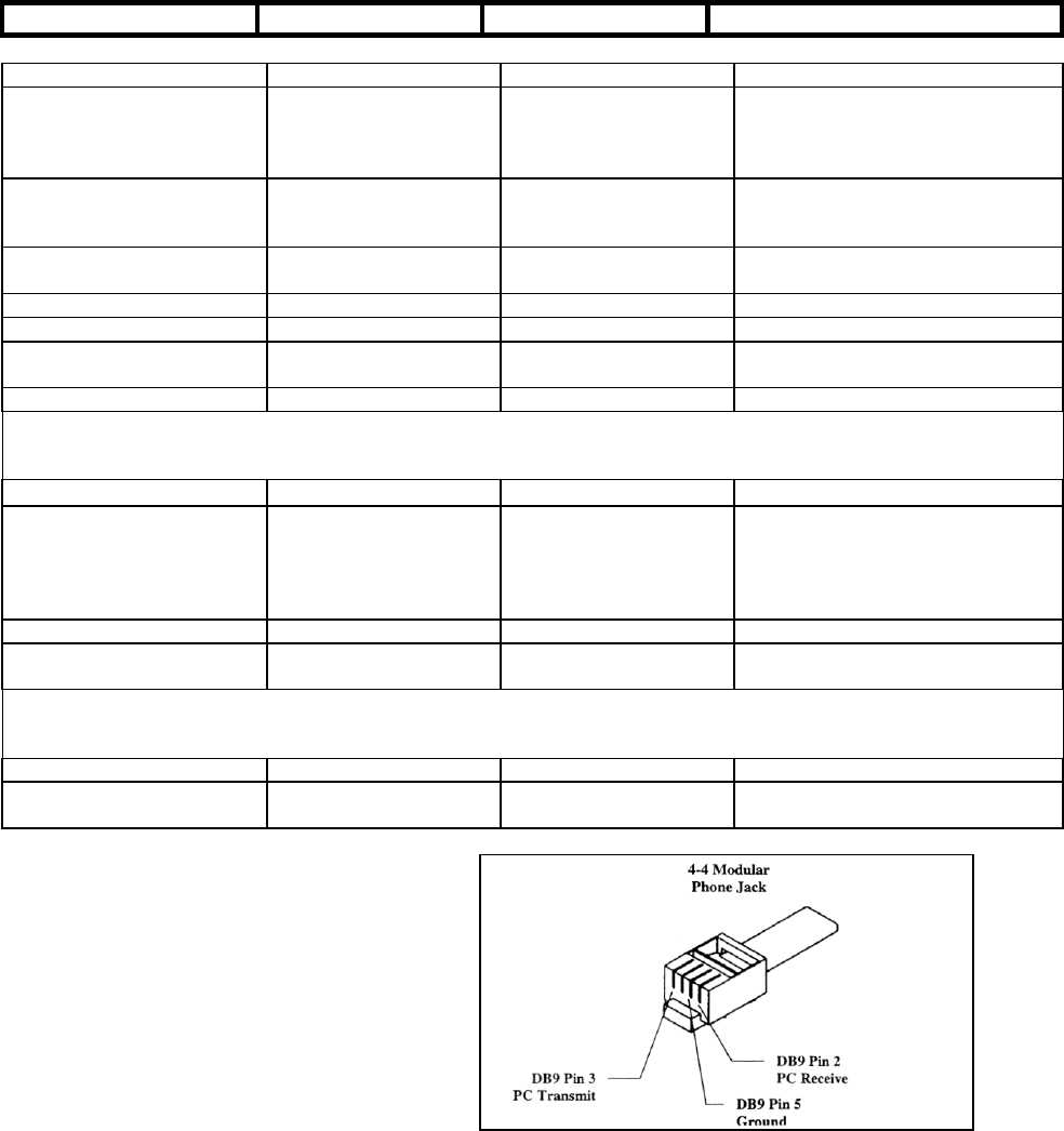
60
Appendix D - RS-232 Connection
You can control your telescope with a computer via the RS-232 port on the computerized hand control and using an
optional RS-232 cable (#93920). Once connected, the telescope can be controlled using popular astronomy software
programs.
Communication Protocol:
The Advanced GT communicates at 9600 bits/sec, No parity and a stop bit. All angles are communicated with 16 bit
angle and communicated using ASCII hexadecimal.
Description PC Command ASCII Hand Control Response Notes
Echo Kx X# Useful to check communication
Goto Azm-Alt B12AB, 4000 # 10 characters sent. B=Command,
12AB=Azm, comma, 4000=Alt. If
command conflicts with slew limits,
there will be no action.
Goto Ra-Dec R34AB, 12CE # Scope must be aligned. If
command conflicts with slew limits,
there will be no action.
Get Azm-Alt Z 12AB, 4000# 10 characters returned,
12AB=Azm, comma, 4000=Alt, #
Get RA-Dec E 34AB, 12CE# Scope must be aligned
Cancel Goto M #
Is Goto in Progress L 0# or 1# 0=No, 1=Yes; "0" is ASCII
character zero
Is Alignment Complete J 0# or 1# 0=No, 1=Yes
Commands below
available on version 1.6
or later
HC version V 22 Two bytes representing V2.2
Stop/Start Tracking Tx
x = 0 (Tracking off)
x = 1 (Alt-Az on)
x = 2 (EQ-N)
x = 3 (EQ-S)
# Alt-Az tracking requires alignment
32-bit goto RA-Dec r34AB0500,12CE0500 #
32-bit get RA-Dec e 34AB0500,12CE0500# The last two characters will always
be zero.
Commands below
available on version 2.2
or later
32-bit goto Azm-Alt b34AB0500,12CE0500 #
32-bit get Azm-Alt z 34AB0500,12CE0500# The last two characters will always
be zero.
The cable required to interface to the telescope
has an RS-232 male plug at one end and a 4-4
telephone jack at the other end. The wiring is
as follows:
61
Additional RS232 Commands
S
Se
en
nd
d
A
An
ny
y
T
Tr
ra
ac
ck
k
R
Ra
at
te
e
T
Th
hr
ro
ou
ug
gh
h
R
RS
S2
23
32
2
T
To
o
T
Th
he
e
H
Ha
an
nd
d
C
Co
on
nt
tr
ro
ol
l
1. Multiply the desired tracking rate (arcseconds/second) by 4. Example: if the desired trackrate is 150
arcseconds/second, then TRACKRATE = 600
2. Separate TRACKRATE into two bytes, such that (TRACKRATE = TrackRateHigh*256 +
rackRateLow). Example: TrackRateHigh = 2 TrackRateLow = 88
3. To send a tracking rate, send the following 8 bytes:
a. Positive Azm tracking: 80, 3, 16, 6, TrackRateHigh, TrackRateLow, 0, 0
b. Negative Azm tracking:80, 3, 16, 7, TrackRateHigh, TrackRateLow, 0, 0
c. Positive Alt tracking: 80, 3, 17, 6, TrackRateHigh, TrackRateLow, 0, 0
d. Negative Alt tracking: 80, 3, 17, 7, TrackRateHigh, TrackRateLow, 0, 0
4. The number 35 is returned from the handcontrol
Send A Slow-Goto Command Through RS232 To The Hand Control
(note: Only valid for motorcontrol version 4.1 or greater)
1. Convert the angle position to a 24bit number. Example: if the desired position is 220°, then
POSITION_24BIT = (220/360)*224 = 10,252,743
2. Separate POSITION_24BIT into three bytes such that (POSITION_24BIT = PosHigh*65536 +
PosMed*256 + PosLow). Exampe: PosHigh = 156, PosMed = 113, PosLow = 199
3. Send the following 8 bytes:
a. Azm Slow Goto: 80, 4, 16, 23, PosHigh, PosMed, PosLow, 0
b. Alt Slow Goto: 80, 4, 17, 23, PosHigh, PosMed, PosLow, 0
4. The number 35 is returned from the handcontrol
Reset The Position Of Azm Or Alt
1. Convert the angle position to a 24bit number, same as Slow-Goto example.
2. Send the following 8 bytes:
a. Azm Set Position: 80, 4, 16, 4, PosHigh, PosMed, PosLow, 0
b. Alt Set Position: 80, 4, 17, 4, PosHigh, PosMed, PosLow, 0
3. The number 35 is returned from the handcontrol
4. Note: If using Motorcontrol version less than 4.1, then send:
a. Azm Set Position: 80, 3, 16, 4, PosHigh, PosMed, PosLow, 0
b. Alt Set Position: 80, 3, 17, 4, PosHigh, PosMed, PosLow, 0
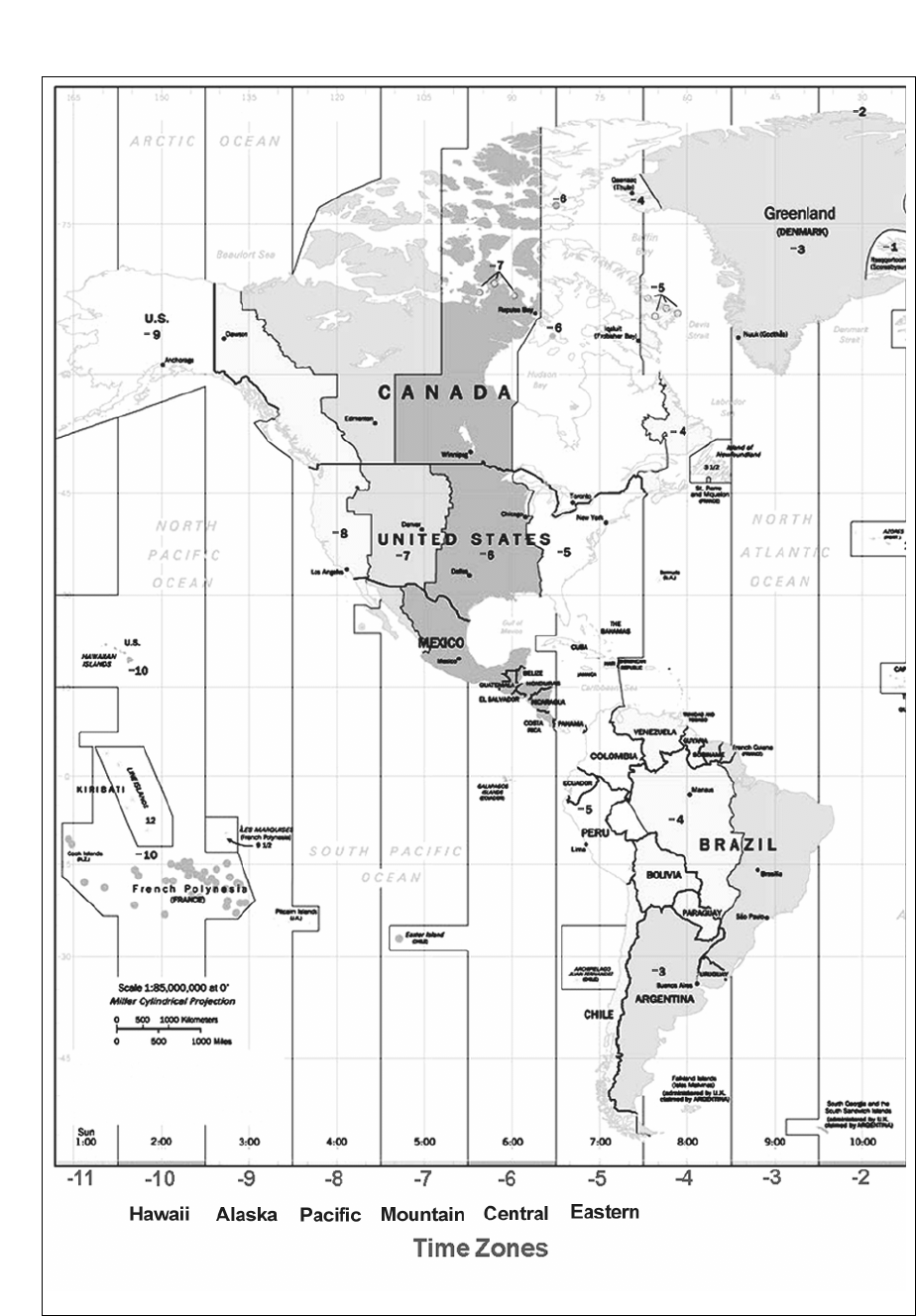
62
APPENDIX E – MAPS OF TIME ZONES

63
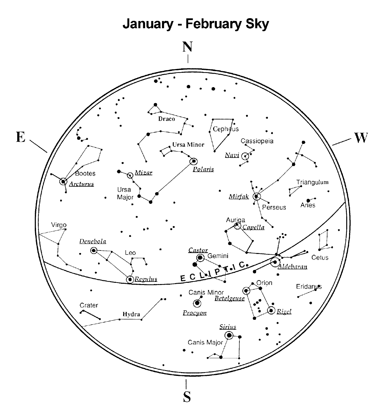
64
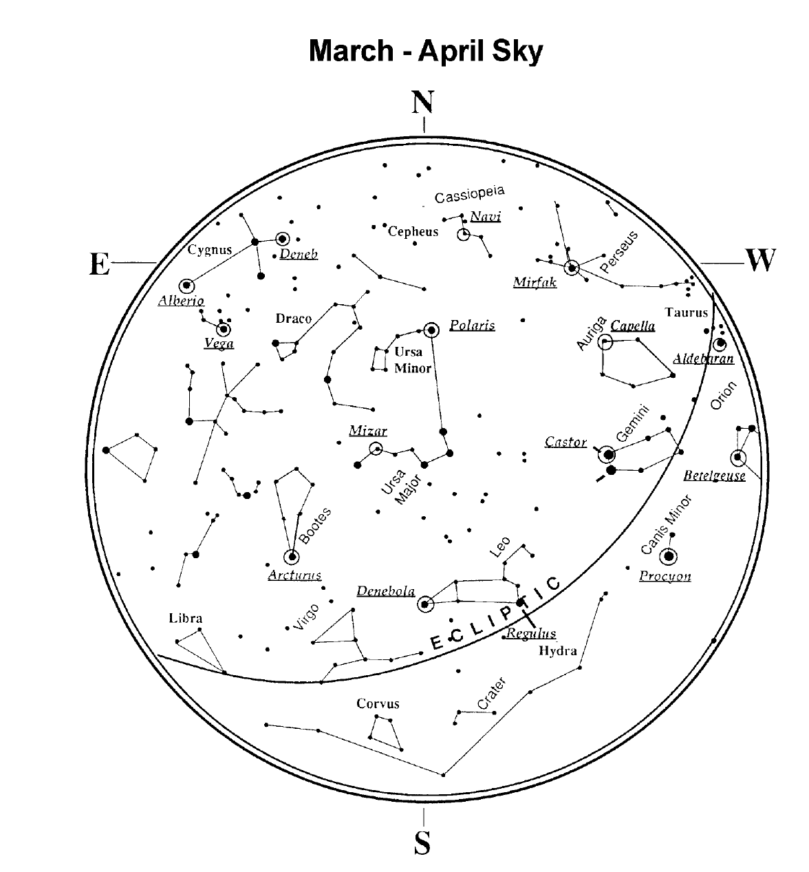
65
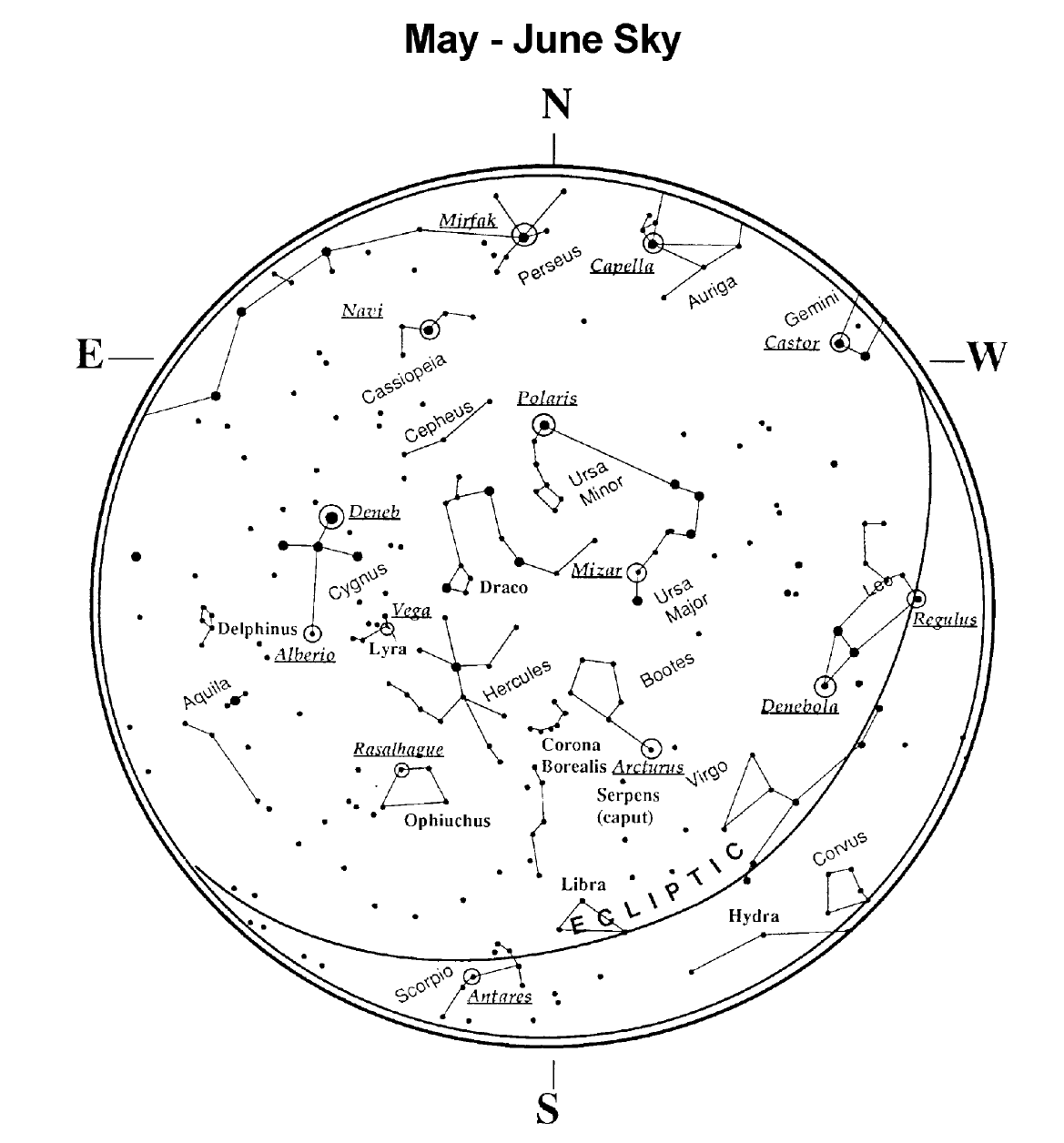
66
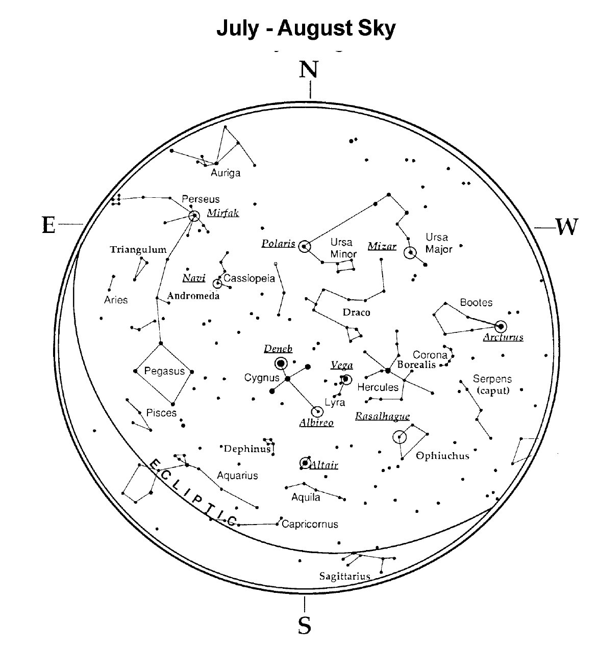
67
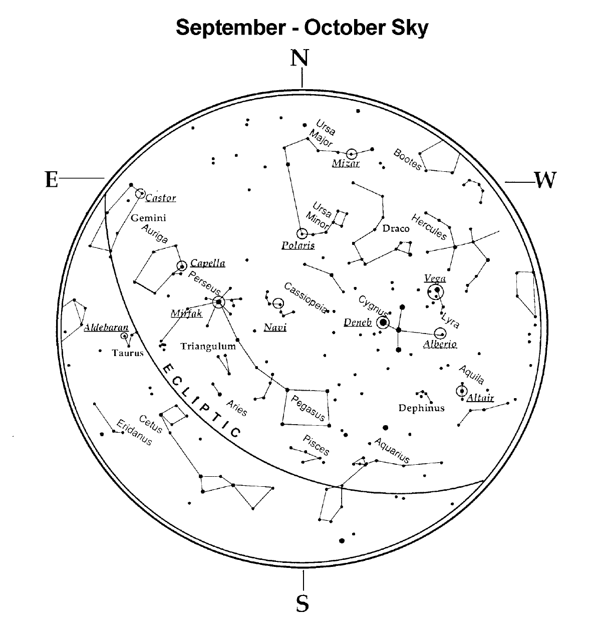
68
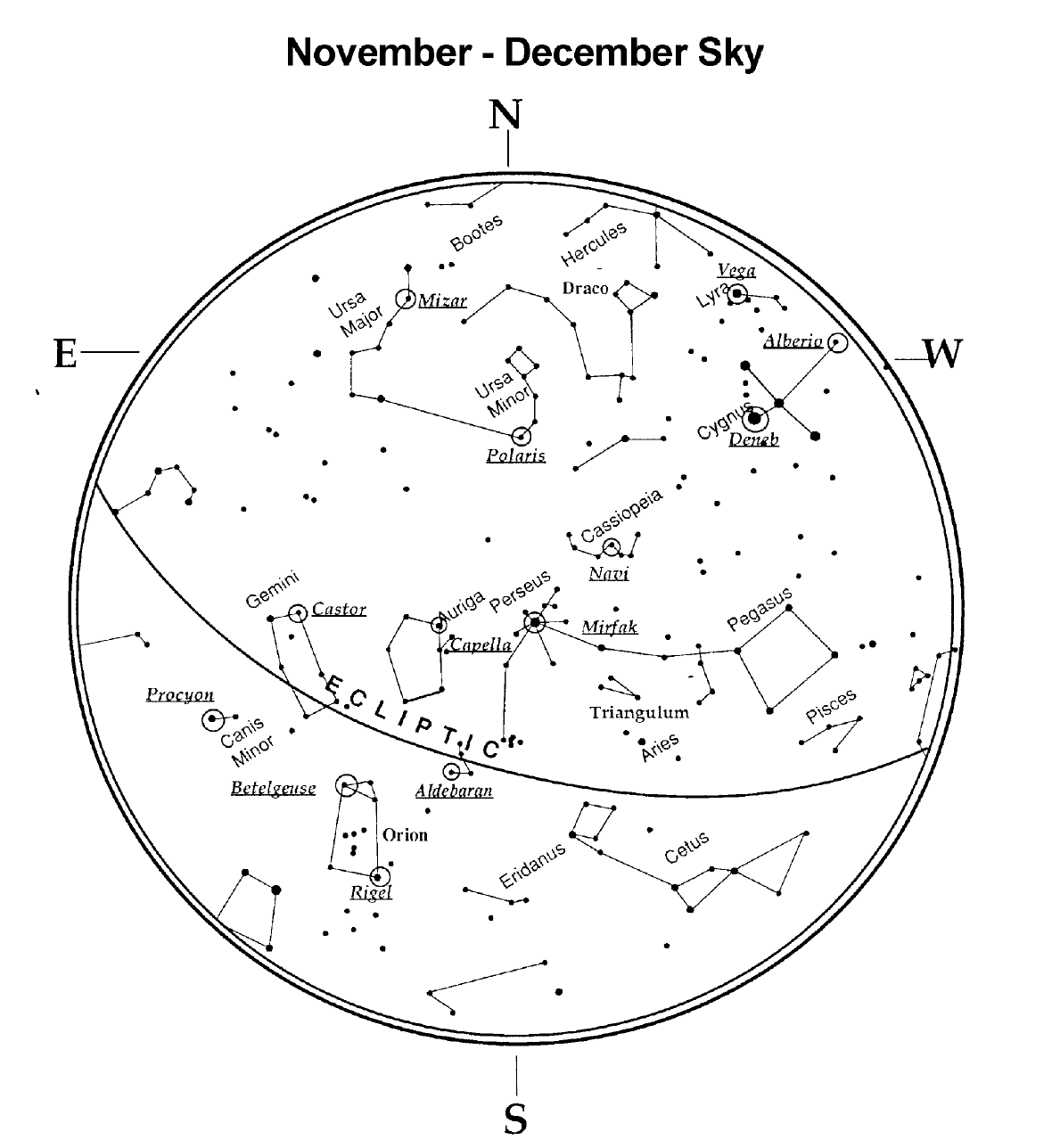
69
3

70
CELESTRON TWO YEAR WARRANTY
A. Celestron warrants this telescope to be free from defects in materials and workmanship for two years. Celestron will repair or
replace such product or part thereof which, upon inspection by Celestron, is found to be defective in materials or workmanship.
As a condition to the obligation of Celestron to repair or replace such product, the product must be returned to Celestron
together with proof-of-purchase satisfactory to Celestron.
B. The Proper Return Authorization Number must be obtained from Celestron in advance of return. Call Celestron at (310) 328-
9560 to receive the number to be displayed on the outside of your shipping container.
All returns must be accompanied by a written statement setting forth the name, address, and daytime telephone number of the
owner, together with a brief description of any claimed defects. Parts or product for which replacement is made shall become
the property of Celestron.
The customer shall be responsible for all costs of transportation and insurance, both to and from the factory of
Celestron, and shall be required to prepay such costs.
Celestron shall use reasonable efforts to repair or replace any telescope covered by this warranty within thirty days of receipt. In
the event repair or replacement shall require more than thirty days, Celestron shall notify the customer accordingly. Celestron
reserves the right to replace any product which has been discontinued from its product line with a new product of comparable
value and function.
This warranty shall be void and of no force of effect in the event a covered product has been modified in design or
function, or subjected to abuse, misuse, mishandling or unauthorized repair. Further, product malfunction or
deterioration due to normal wear is not covered by this warranty.
CELESTRON DISCLAIMS ANY WARRANTIES, EXPRESS OR IMPLIED, WHETHER OF MERCHANTABILITY OF
FITNESS FOR A PARTICULAR USE, EXCEPT AS EXPRESSLY SET FORTH HEREIN.
THE SOLE OBLIGATION OF CELESTRON UNDER THIS LIMITED WARRANTY SHALL BE TO REPAIR OR
REPLACE THE COVERED PRODUCT, IN ACCORDANCE WITH THE TERMS SET FORTH HEREIN. CELESTRON
EXPRESSLY DISCLAIMS ANY LOST PROFITS, GENERAL, SPECIAL, INDIRECT OR CONSEQUENTIAL DAMAGES
WHICH MAY RESULT FROM BREACH OF ANY WARRANTY, OR ARISING OUT OF THE USE OR INABILITY TO
USE ANY CELESTRON PRODUCT. ANY WARRANTIES WHICH ARE IMPLIED AND WHICH CANNOT BE
DISCLAIMED SHALL BE LIMITED IN DURATION TO A TERM OF TWO YEARS FROM THE DATE OF ORIGINAL
RETAIL PURCHASE.
Some states do not allow the exclusion or limitation of incidental or consequential damages or limitation on how long an implied
warranty lasts, so the above limitations and exclusions may not apply to you.
This warranty gives you specific legal rights, and you may also have other rights which vary from state to state.
Celestron reserves the right to modify or discontinue, without prior notice to you, any model or style telescope.
If warranty problems arise, or if you need assistance in using your telescope contact:
Celestron
Customer Service Department
2835 Columbia Street
Torrance, CA 90503 U.S.A.
Tel. (310) 328-9560
Fax. (310) 212-5835
Monday-Friday 8AM-4PM PST
This warranty supersedes all other product warranties.
NOTE: This warranty is valid to U.S.A. and Canadian customers who have purchased this product from an Authorized
Celestron Dealer in the U.S.A. or Canada. Warranty outside the U.S.A. and Canada is valid only to customers who purchased
from a Celestron Distributor or Authorized Celestron Dealer in the specific country and please contact them for any
warranty service.

Celestron
2835 Columbia Street
Torrance, CA 90503 U.S.A.
Tel. (310) 328-9560
Fax. (310) 212-5835
Web site at http//www.celestron.com
Copyright 2003 Celestron
All rights reserved.
(Products or instructions may change
without notice or obligation.)
Item # 31061-INST
Printed in China
$10.00
09-03
