Celletra C-BCL Cellular Multi-Channel Amplifier Antenna User Manual an
Celletra Ltd. Cellular Multi-Channel Amplifier Antenna an
UserManual.wiki
>
Celletra
>
C BCL User Manual
users manual
Navigation menu
Upload a User Manual
Namespaces
Wiki Guide
HTML
PDF
Info
Views
User Manual
Discussion / Help
Navigation
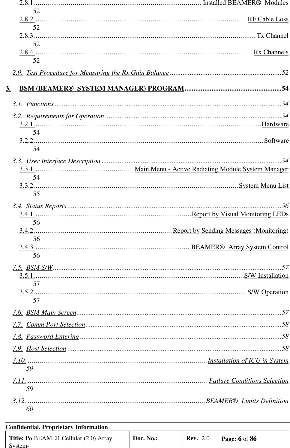
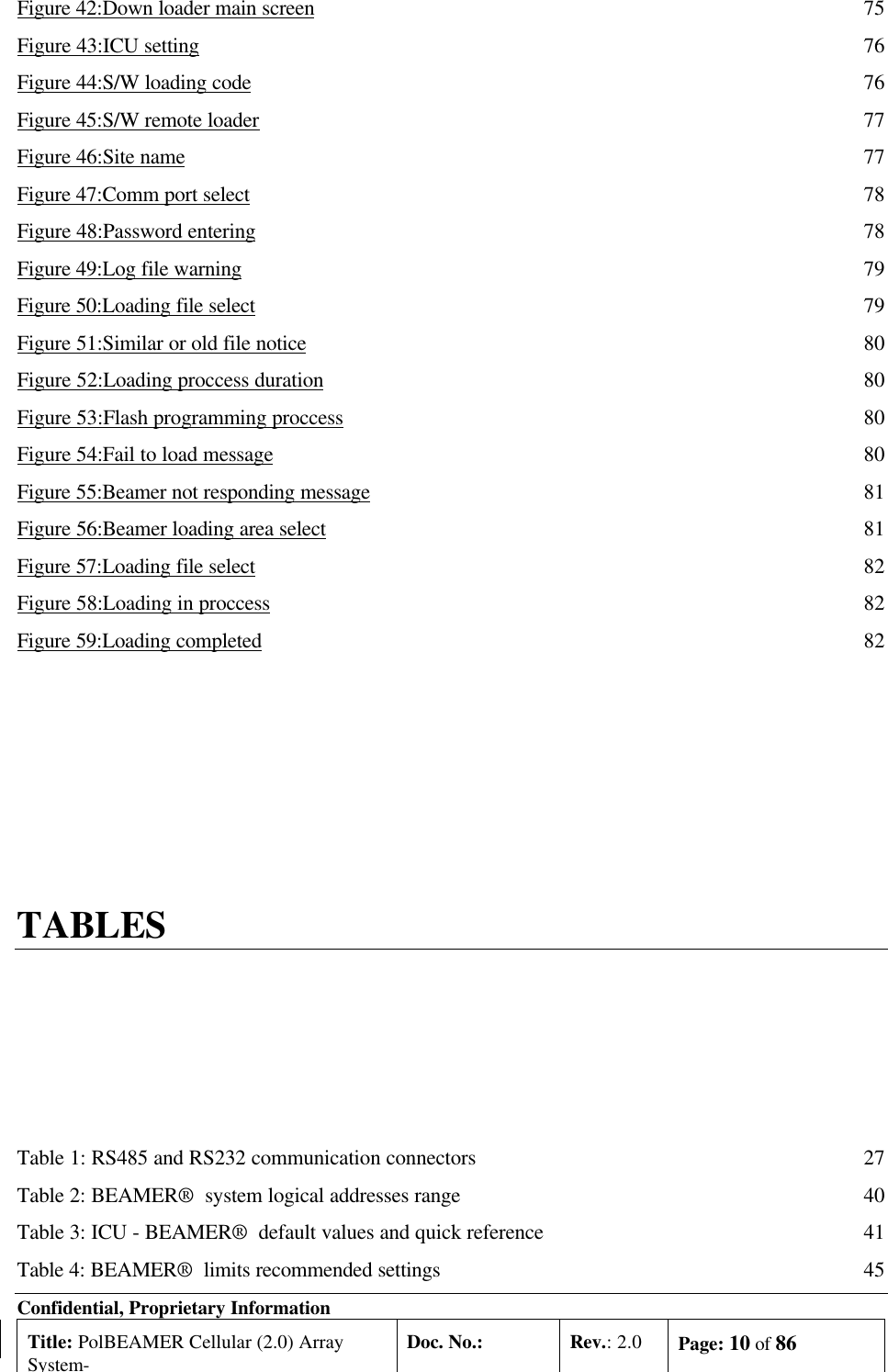
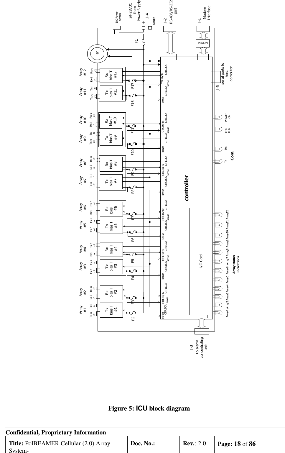
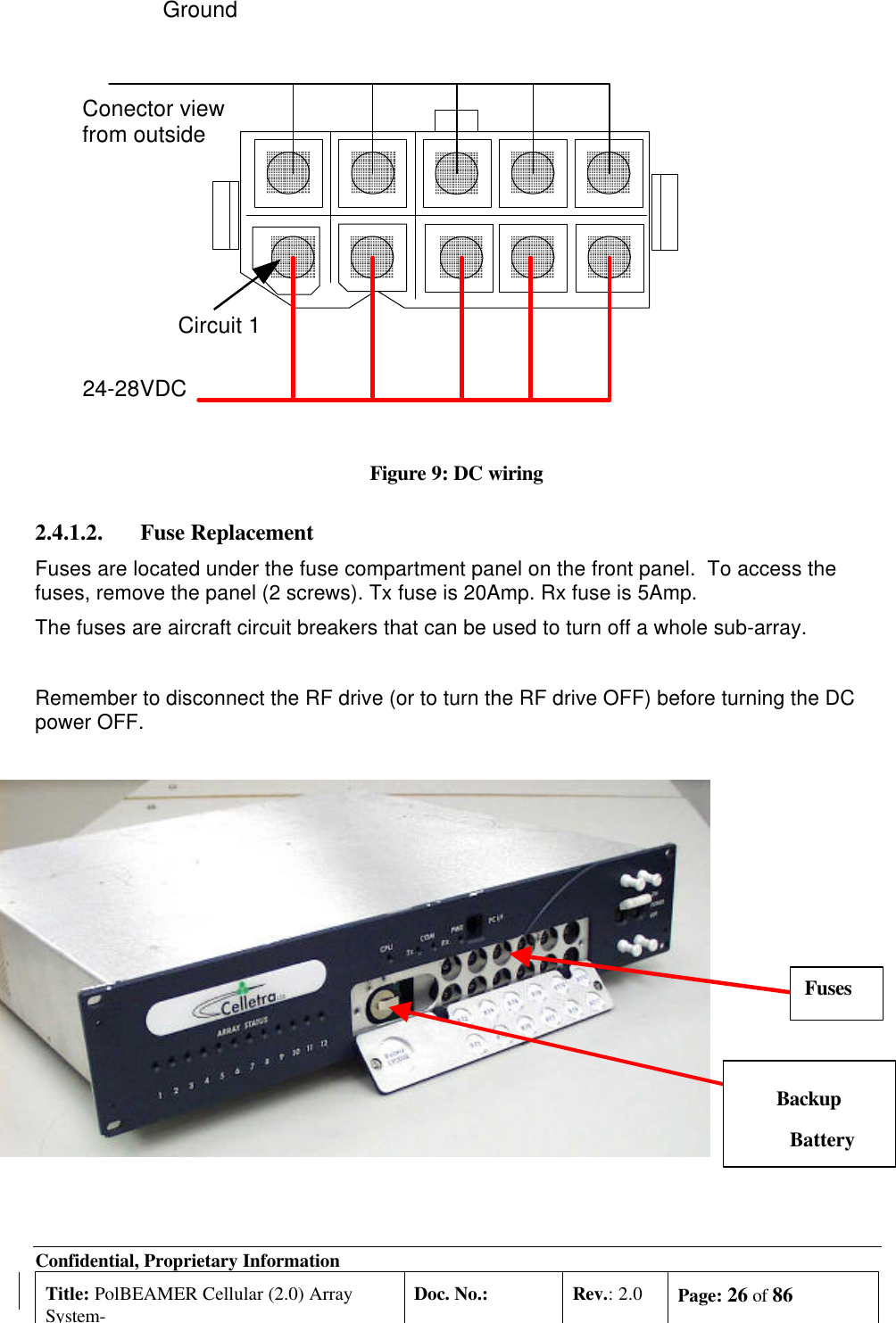
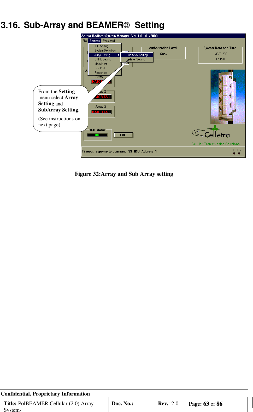
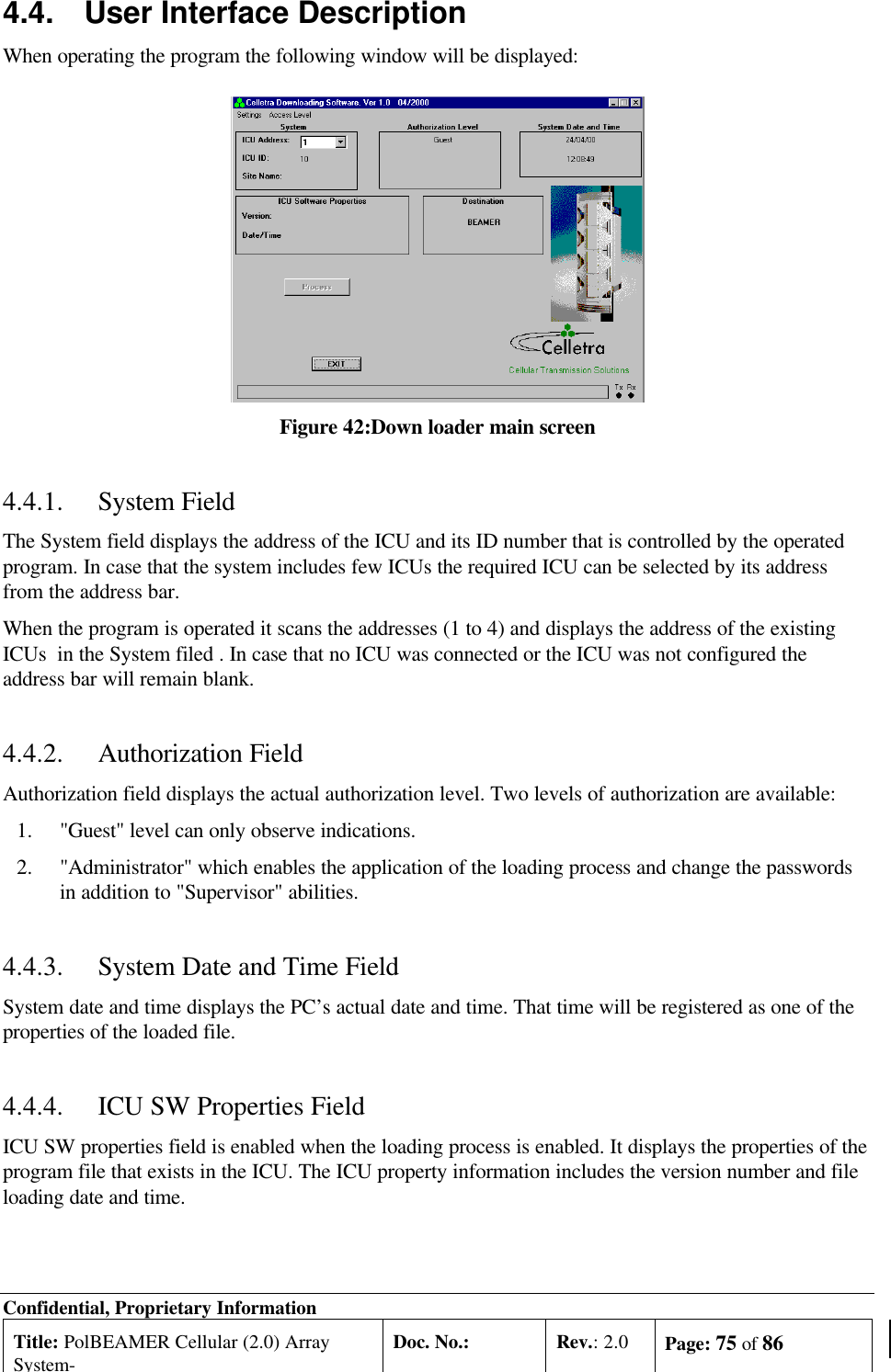
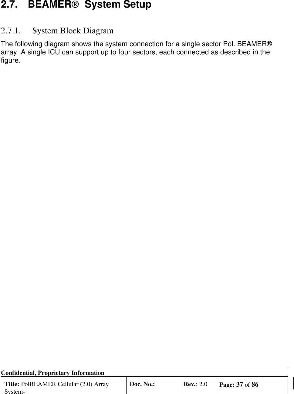
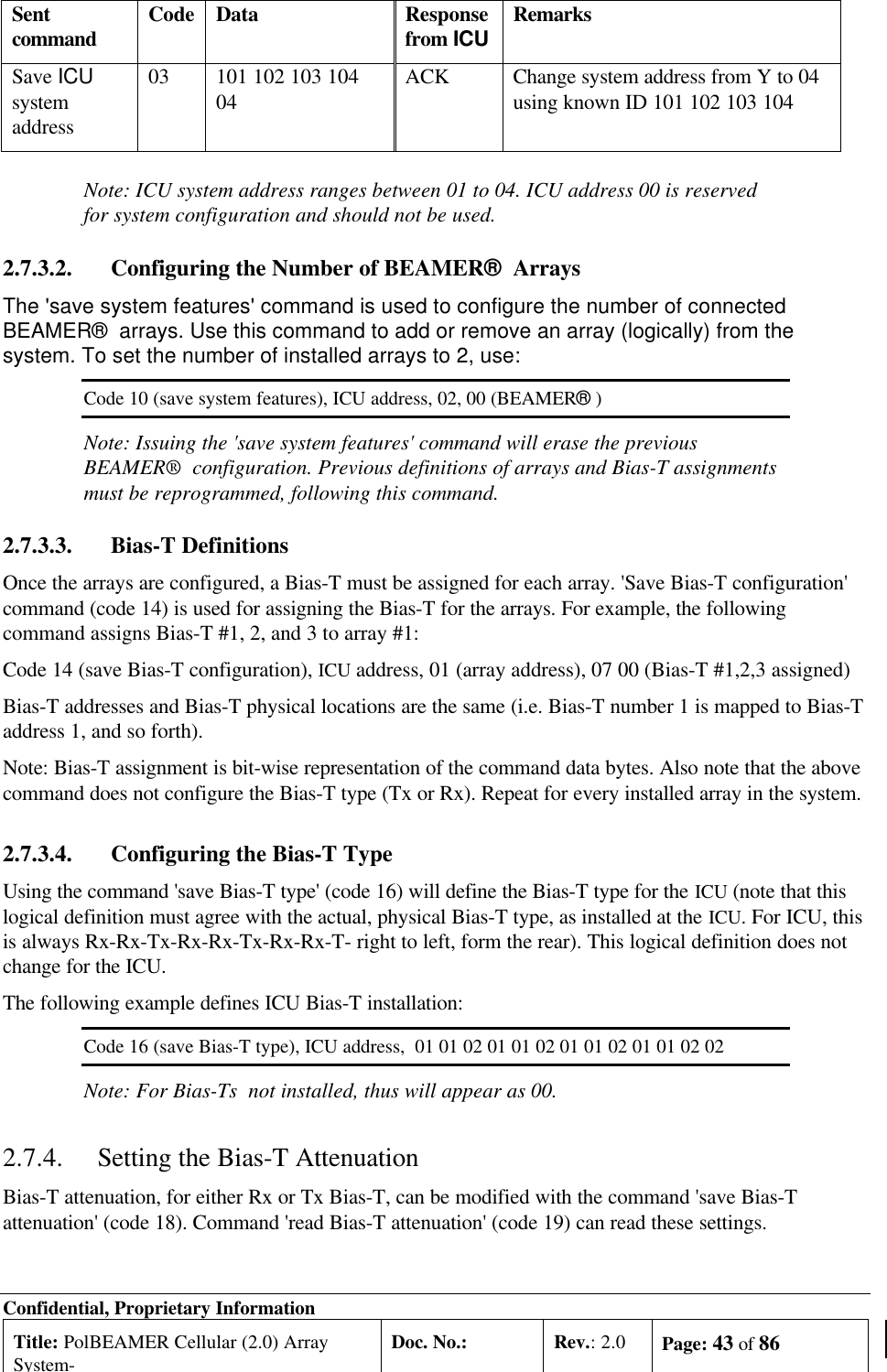
![Confidential, Proprietary InformationTitle: PolBEAMER Cellular (2.0) ArraySystem-Doc. No.: Rev.: 2.0 Page: 29 of 862.4.4. Bias-TsIn this manual, Bias-Ts are also termed 'sub-array', since each Bias-T can serves anindependent portion of an array (i.e., Tx sub-array or Rx1 and Rx2 sub-arrays, which are allphysically part of the same array, but are logically independent entities).The Bias-Ts serve four purposes:1.Supply DC voltage to the BEAMER® modules within the sub-array.2.Provide DCA controlled RF amplification stage, to overcome possible RF distribution losses andto provide control on the transmitted or received output power per sub-array.3.Connect the BEAMER® modules Telemetry to the ICU controller via the superimposed FSKlink.4.Enable the S/W downloading to each BEAMER® of the array using the Telemetry channel.The sub-array direction of the ICU Bias-T connector is N-type connector, capable ofsupporting the DC current to the sub-array. The BTS side is TNC type connector. Thefollowing figure shows the active Bias-T location on the ICU.Figure 12: Bias-T inputs / outputs and numberingViewed from right to left, the Bias-Ts are organized as:[Rx1-Rx2-Tx], [Rx1-Rx2-Tx], [Rx1-Rx2-Tx], [Rx1-Rx2-Tx]Bias-T number 1 is on the far right going to Bias-T number 12 at the near left. These(physical) numbers also serve as logical addresses for the Bias-T (sub-arrays) at the systemsetup.In case less arrays are integrated in the system, the number of Bias-Ts will bereduced.](https://usermanual.wiki/Celletra/C-BCL/User-Guide-182887-Page-29.png)


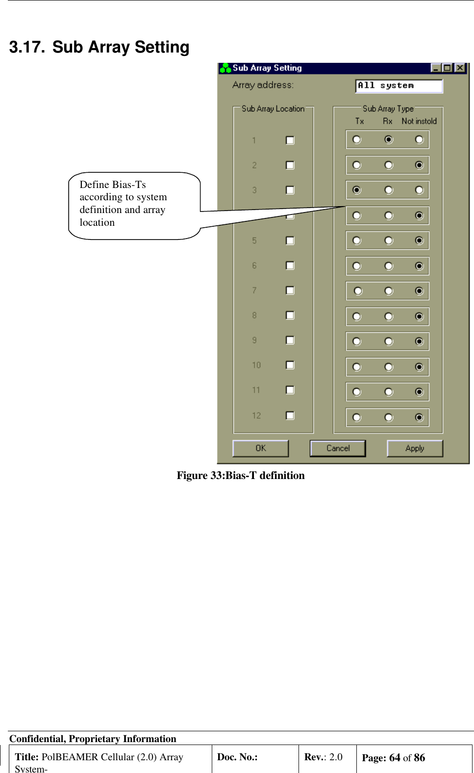
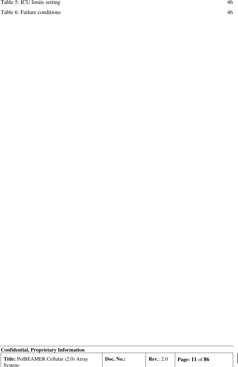
![Confidential, Proprietary InformationTitle: PolBEAMER Cellular (2.0) ArraySystem-Doc. No.: Rev.: 2.0 Page: 40 of 86• Sub-arrays (10,11,12) - array#4The following table summarizes the available address range for the system entities:Table 2: BEAMER® system logical addresses rangeName Address rangeICU 01 to 04. Address 00 reserved for testingArray 01 to 12(03). For Micro- ICU: maximum 03 (always pol. BEAMER® )Sub-array (Bias-T) 01 to 12(09). For Micro- ICU: Same as physical address, maximum 09.BEAMER® 01 to 16. Address 00 reserved for testing2.7.3. System Configuration and SettingSome of the ICU setup are already configured for the needed system configuration. This setup is savedon the ICU's Flash memory. Using the PC to ICU protocol commands, you can verify that the ICU isproperly set.The following sections will guide you through the process of ICU setup verification. You can modify thesetup to match your configuration at any time.Throughout this section, some command examples and data will be used. As a rule, all commands dataand commands codes are given here in decimal representation, unless specifically specified, using 'H'prefix for hex numbering. Also, it is assumed that the reader has some knowledge with the PC to ICUprotocol, given in [1]. The command sequence described in this section should be referred to as a systemconfiguration guide, not as a PC to ICU programming manual. For more information, refer to theapplicable documentation listed at the beginning of this chapter.Before setting up the system, avoid connect RF cables between the ICU and the BEAMER® array.Since the Tx and Rx gain are not calibrated yet, this is done to protect the BTS interface and theBEAMER® array from overdrive conditions.The following table can be used as a reference for the ICU and BEAMER® array setting. The tablespecifies the pre-set default values and points to the specific command code, used for reading or savinga parameter value.Note: Many values are not set. The following sections will instruct you how to setthese values, tailored to the specific on-site installation.Caution: some values ( such as RS-232/RS-485 switch ,Time out and codes1,137,141,145-149) are factory set and should not be changed on location. In partICU are, these values relate to the BEAMER® array calibration and operationmodes. Modification of these values, without coordination and specificauthorization from Celletra engineering, can cause invalid array performance andshould be avoided. The changes are possible by the highest passwordauthorization only.](https://usermanual.wiki/Celletra/C-BCL/User-Guide-182887-Page-40.png)
![Confidential, Proprietary InformationTitle: PolBEAMER Cellular (2.0) ArraySystem-Doc. No.: Rev.: 2.0 Page: 42 of 862.7.3.1. Set ICU Operation ModeThe ICU configuration setup can only be changed when the ICU is set to SLAVE mode. Thedefault ICU configuration is AUTO. To switch to slave mode use 'save operation mode'command (code 05), with parameter 01. Note, however, that if the ICU communication is leftunattended for longer than the time out, defined by 'save time out' command (code 36)[default value is 5 minute], the ICU will automatically switch back to AUTO mode. Only thefollowing commands are available in AUTO mode:• Save operation mode (05)• Read operation mode (06)• Save control mode (07)• Read control mode (08)• Read array status (28)• Read BEAMER® status (29)• Read ICU status (30)In AUTO mode, any other command will be responded by an error message (code 34, data01 xx xx xx xx).2.7.3.1.1. Checking the ICU System Address and ICU IDThe ICU system address and the ICU ID can be easily modified1, to suit your needs. To change the ICUaddress you should know the ICU ID.You can read the ICU system address and its ID as follows:Sent command Code Data Response from ICU RemarksRead ICU ID 02 00 X1 X2 X3 X4 Every ICU answers whenaddressed by 00Read ICUsystem Address04 X1 X2 X3 X4 X1 X2 X3 X4 Y Use ICU ID (X1 X2 X3 X4) tofind ICU address (Y)2.7.3.1.2. Changing the ICU System AddressCaution: ICU ID is located on the unit label. The unit label is attached to the -ICUfront panel (the fuse panel). The ICU ID is its physical number. Do not modify theICU ID, unless authorized by Celletra engineering support.Once the ICU ID and system address are known, you can easily modify the system addressto any other value. The following sequence demonstrates how to change the ICU systemaddress from Y to 04, using known ICU ID 101 102 103 104.Sentcommand Code Data Responsefrom ICU Remarks 1 ICU ID cannot be changed in operation mode. Issuing command code 01 in operation mode will produce anerror message.](https://usermanual.wiki/Celletra/C-BCL/User-Guide-182887-Page-42.png)
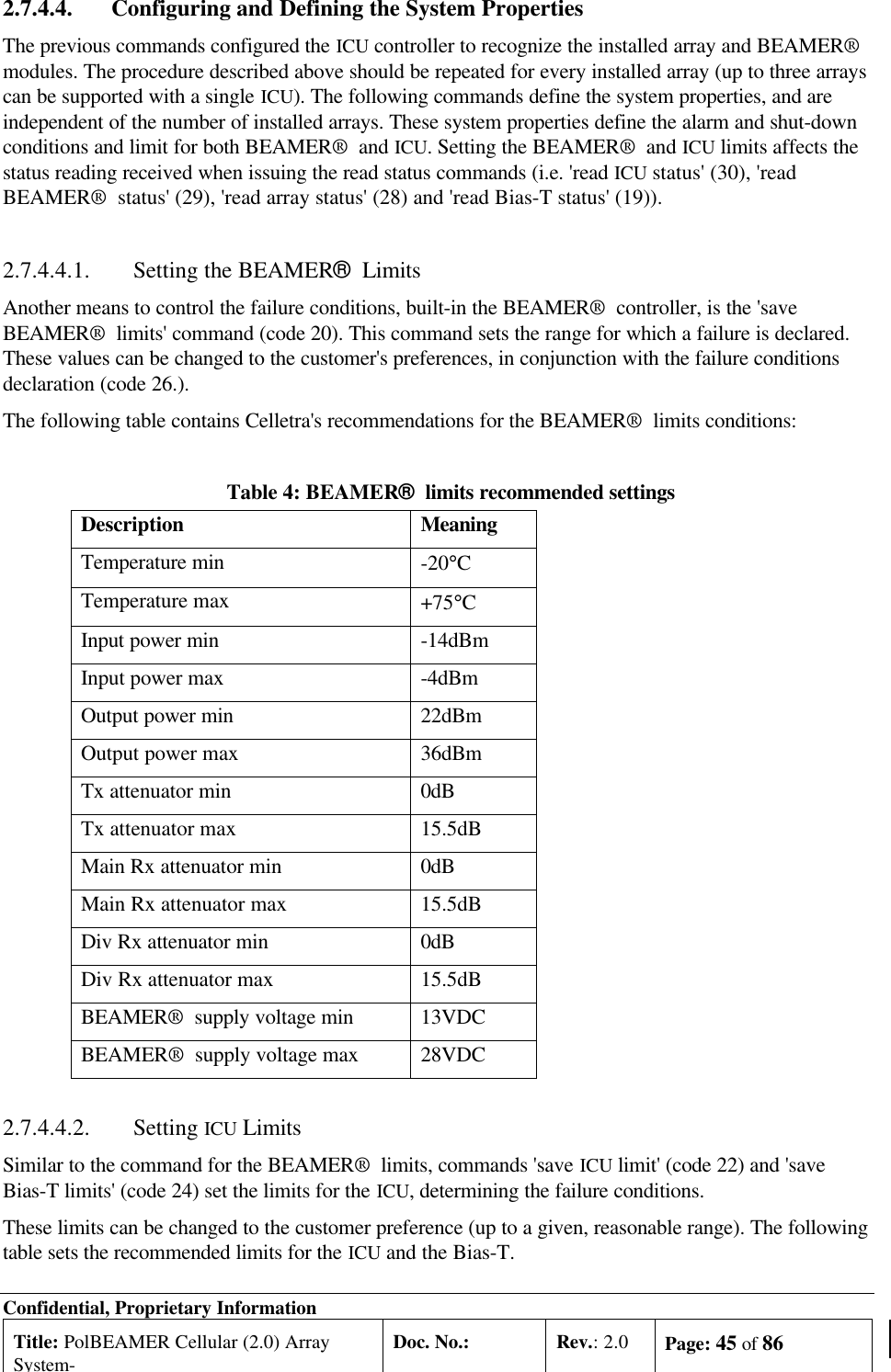
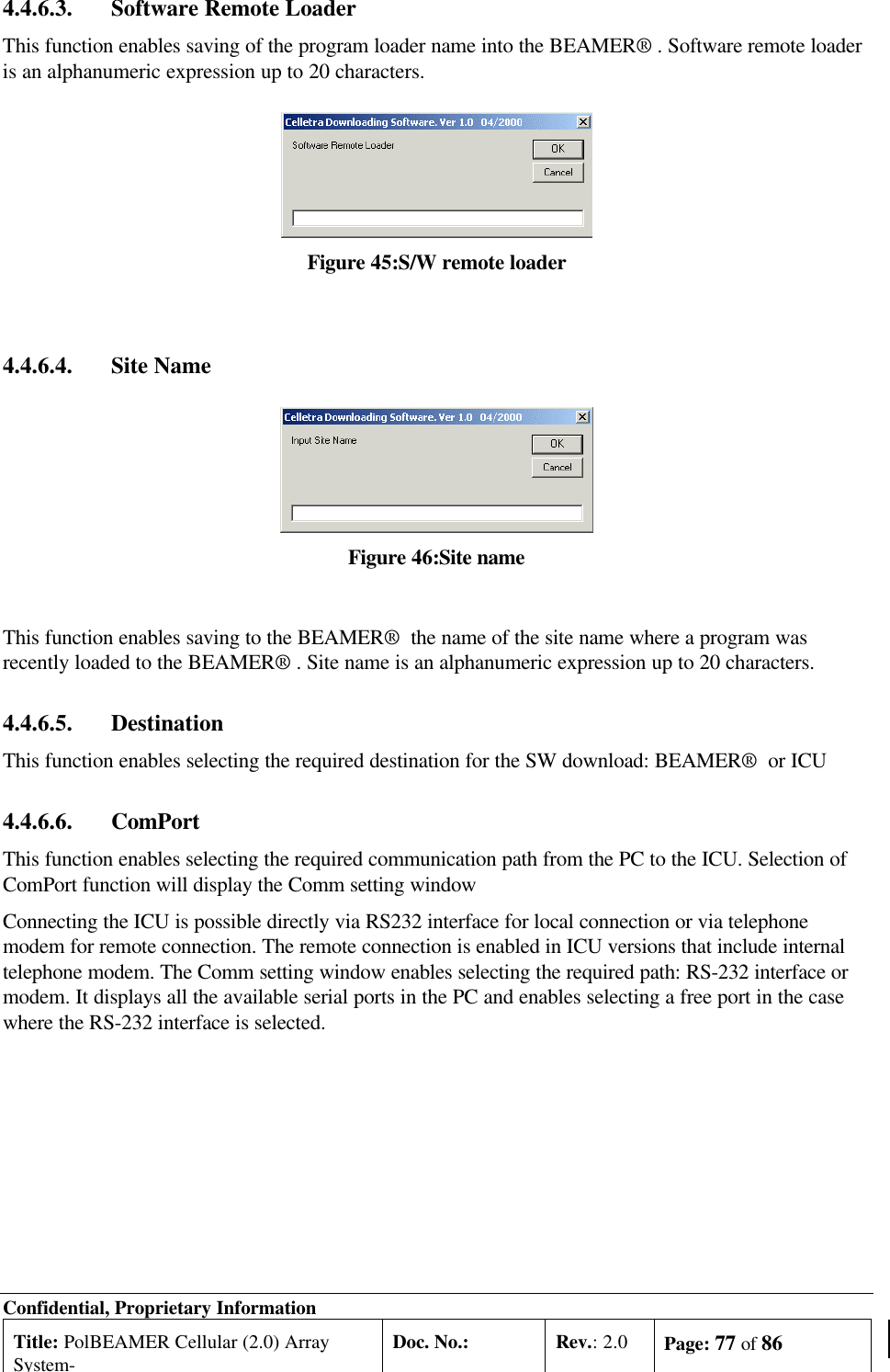
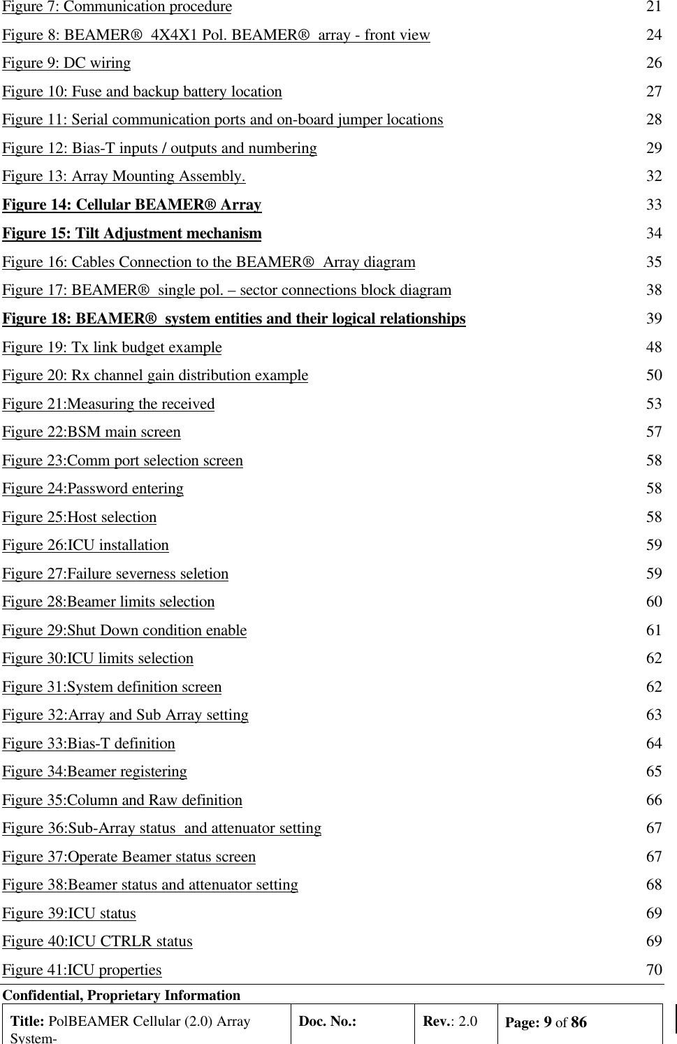
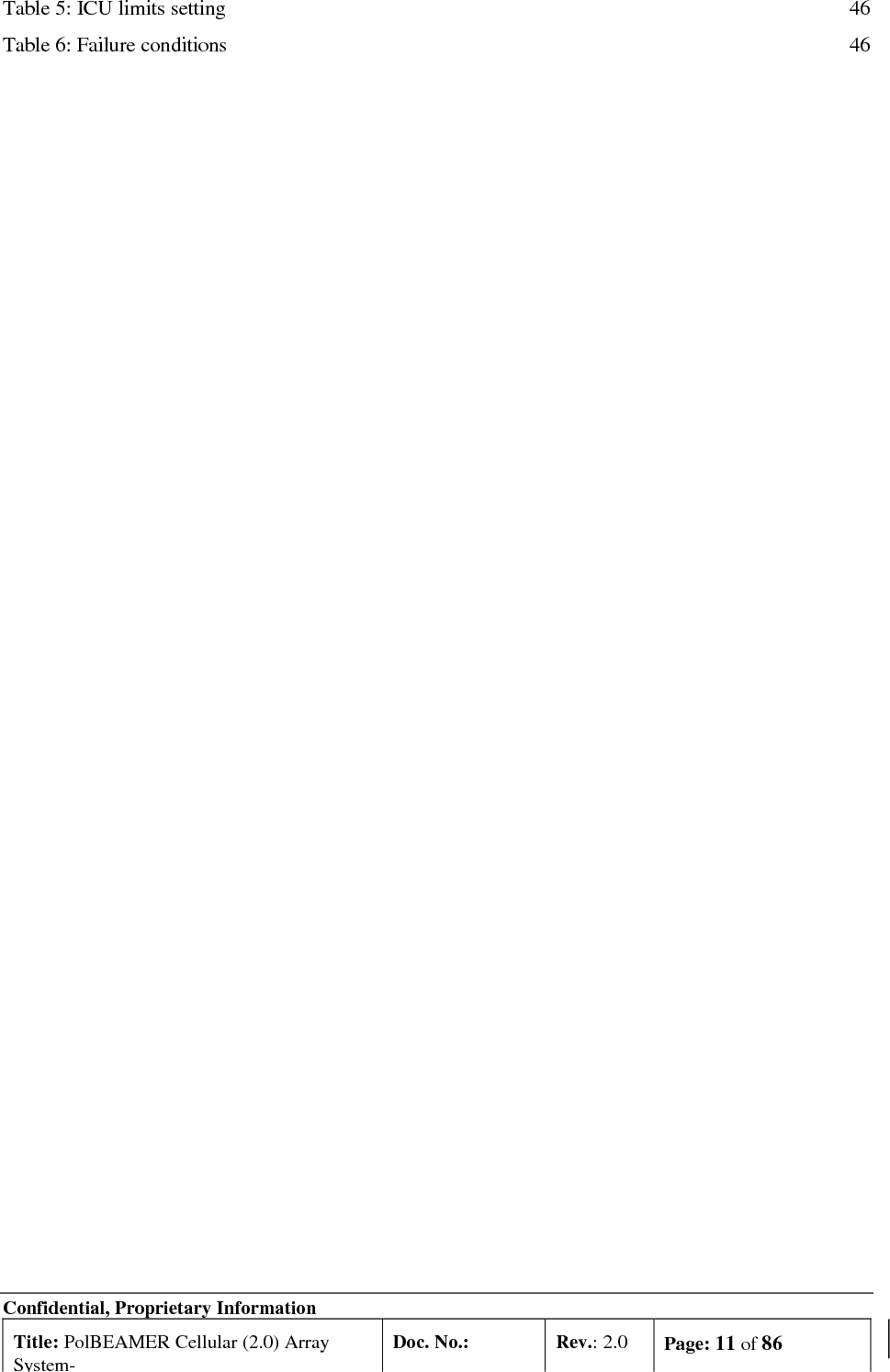
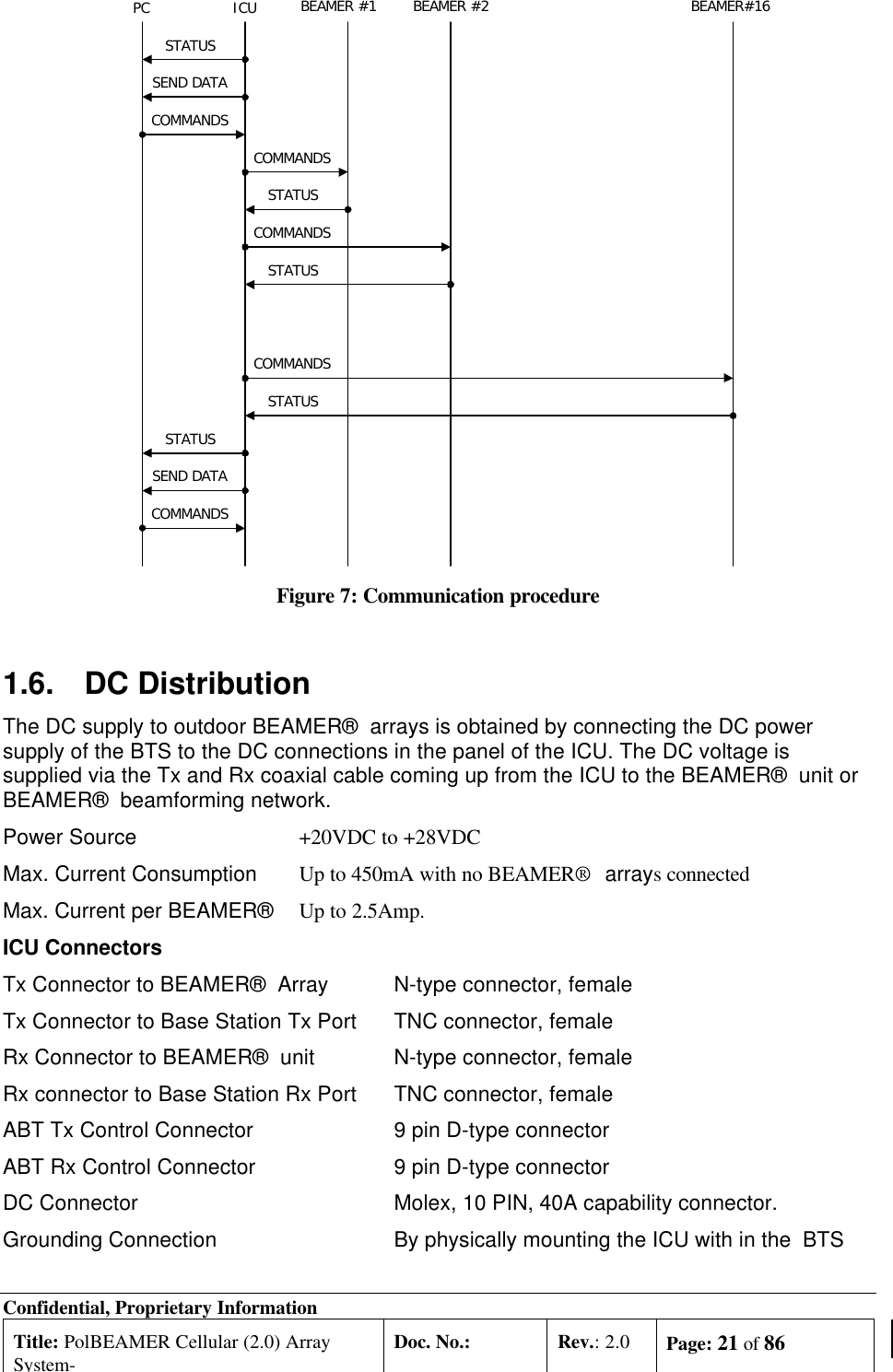
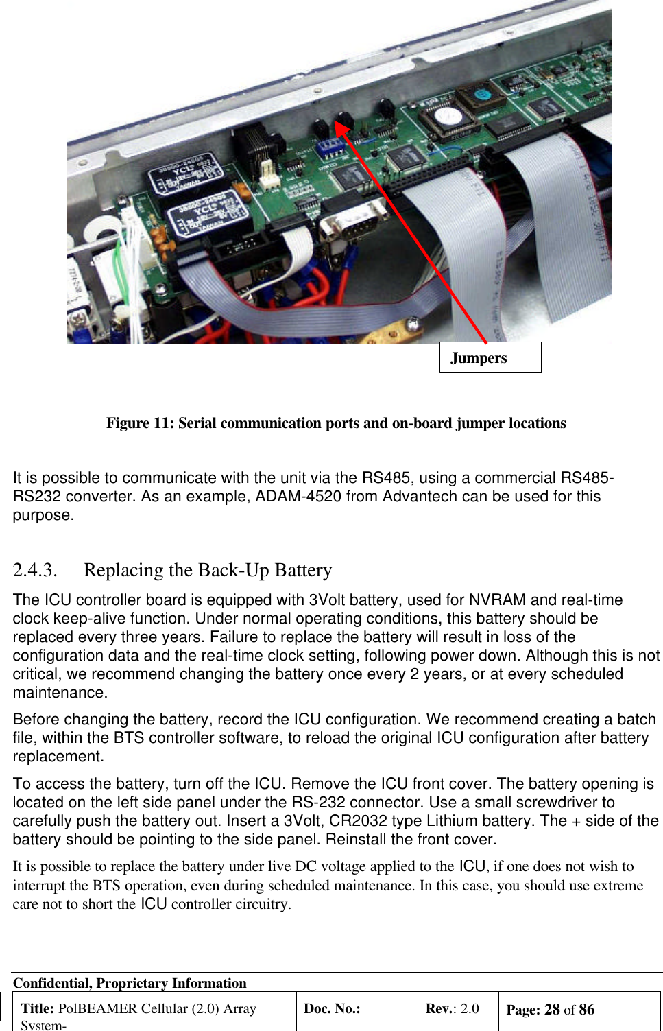
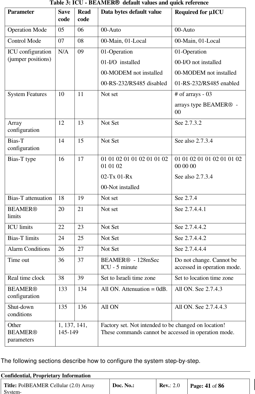
![Confidential, Proprietary InformationTitle: PolBEAMER Cellular (2.0) ArraySystem-Doc. No.: Rev.: 2.0 Page: 48 of 86BeamerArray[G=13dBi]G1:4DividerLoss=LGABTBTSInputPinPout (max)=10dBmG=30±1dBGC=0 to15.5dBL=0 to4dBPout =35dBmG=44±0.5dBGC=0 toEIRP=54dBm(max)Combinedin the AirBeamer 4GGBeamer 3GBeamer 2Beamer1-10dbmPin=-28dBm to -15dBm+1dbmCoax15.5dB+41dbm[L=6db]-3dbm -9dbmFigure 19: Tx link budget example 2.7.5.1. Estimating the Required Tx-ABT GainThe purpose of this procedure is to verify that the BEAMER® system available gain is sufficient tocover the expected RF losses, before starting the actual Tx calibration.](https://usermanual.wiki/Celletra/C-BCL/User-Guide-182887-Page-48.png)
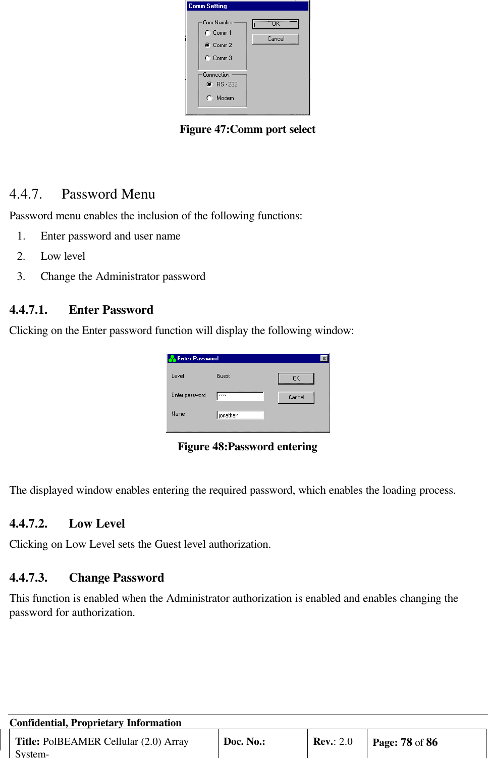
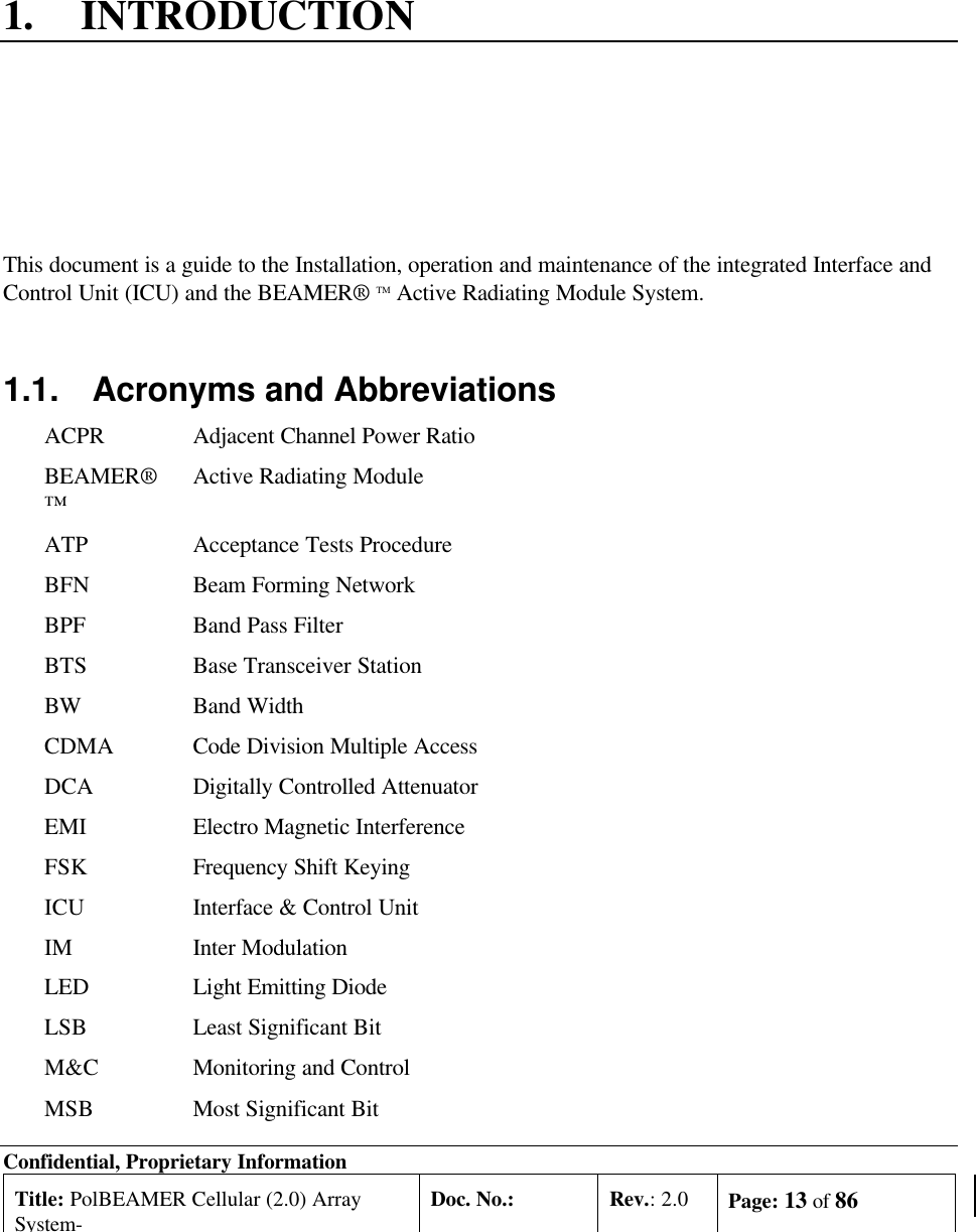
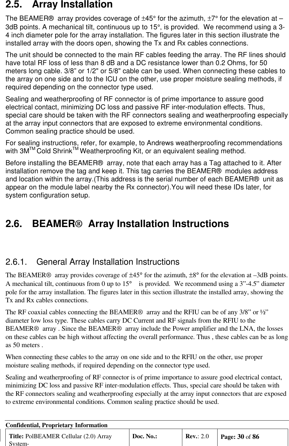
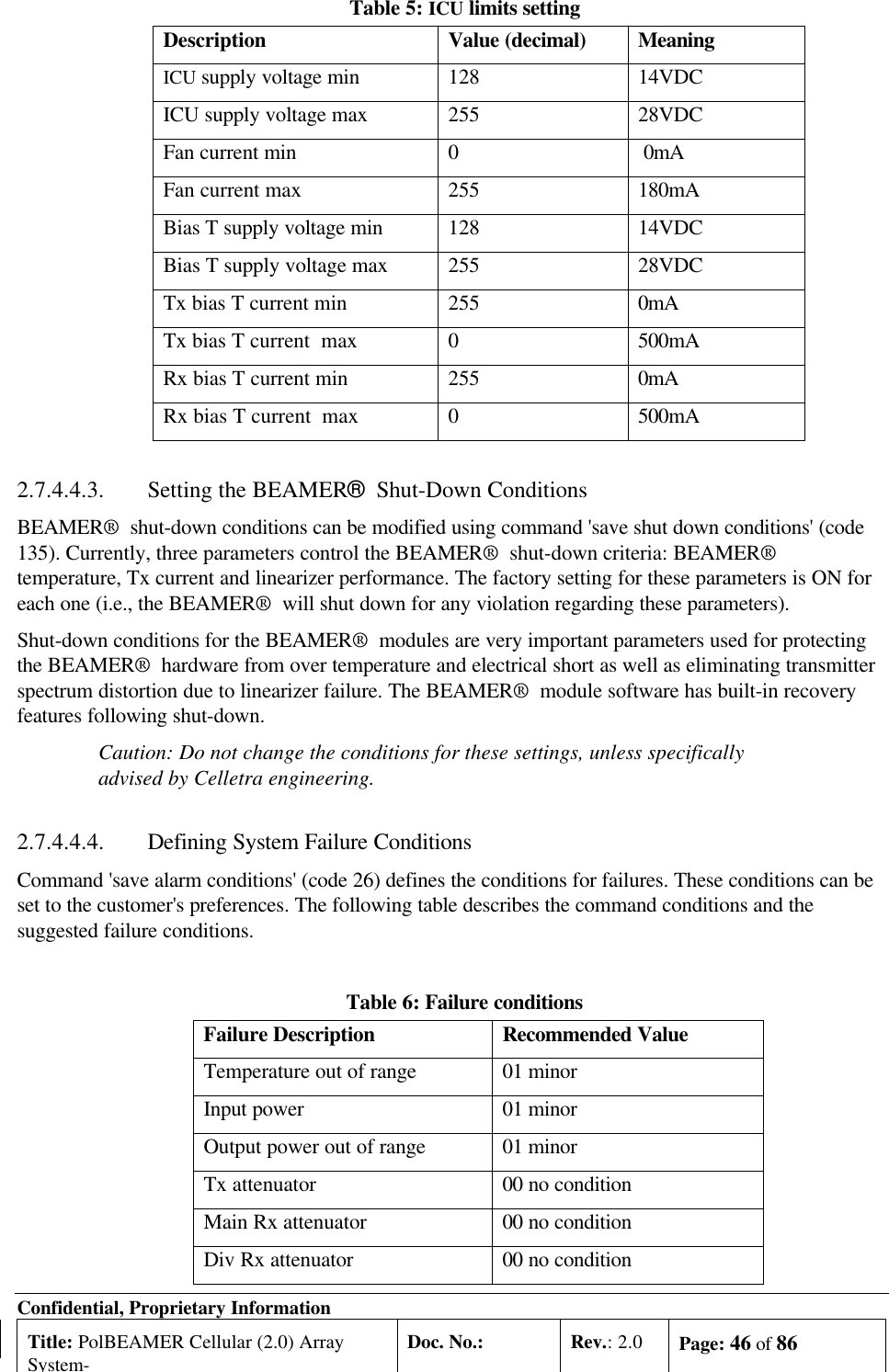
![Confidential, Proprietary InformationTitle: PolBEAMER Cellular (2.0) ArraySystem-Doc. No.: Rev.: 2.0 Page: 50 of 86BeamerArray[G=13.5dBi]2:1RearCombiner[L=0.3dB]RF CoaxLoss=LGABTBTSG=6±1dBGC=0 to 15.5dBL=3 to 8dBG=30±1dBGC=0 to 15.5dB2:1Rear[L=0.3dB]BTS downConverterRX2RX1Noise PinInput-82dbm-88dbmNoise Figure=4dbCombiner-82dbm-112dbmBeamer-82dbmFigure 20: Rx channel gain distribution exampleThe main factors to consider, when calibrating the Rx channels are as follows:The total system gain should be high enough to assure that the system input noise level will be drivenbeyond the down-converter output AGC nominal bias point, when the BEAMER® plus BTS downconverter gain is at the maximum available gain.The total BEAMER® system gain should not be too high, to avoid excessive reduction of the systemIIP3 thus increasing the system susceptibility to interference. As a rule of thumb, an excess gain of 6-10dB beyond the minimum required gain from rule 1 is the maximum required gain for rule 2.For efficient diversity operation, even at relatively low signal to noise ratio, the two Rx channels gainsshould be balanced to ±1dB.The BEAMER® -Rx programming property offers the system integrator the tool for calibrating thesystem gain, in full accordance with the above rules.The proper trade-off between these rules should be found. As an example, if the two Rx channel arevery much unbalanced an excessive gain increase might be required at one channel, causing possibleinterference susceptibility on that channel.](https://usermanual.wiki/Celletra/C-BCL/User-Guide-182887-Page-50.png)