Celletra C-CPB Single Channelized PCS Coverage Enlightener Beamer User Manual Ope
Celletra Ltd. Single Channelized PCS Coverage Enlightener Beamer Ope
UserManual.wiki
>
Celletra
>
C CPB User Manual
manual
Navigation menu
Upload a User Manual
Namespaces
Wiki Guide
HTML
PDF
Info
Views
User Manual
Discussion / Help
Navigation
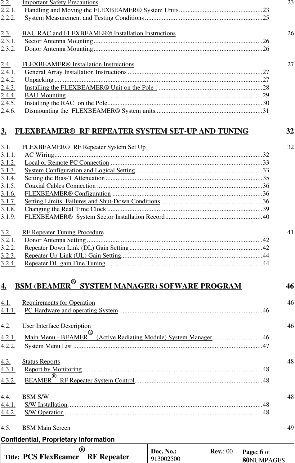
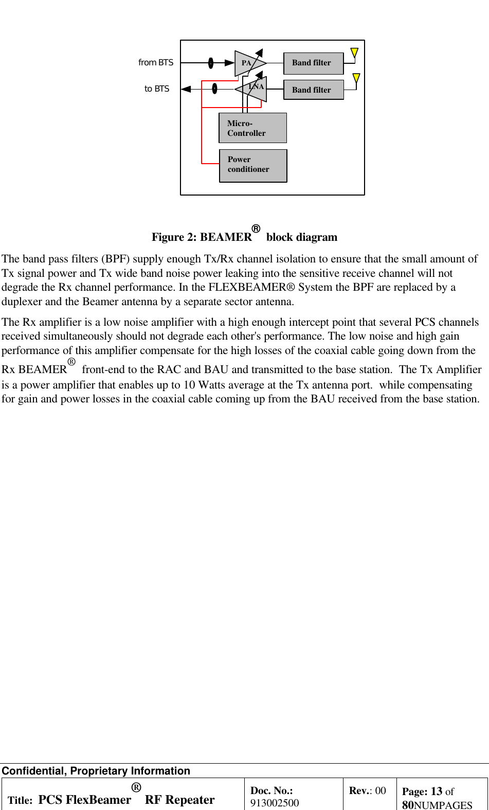
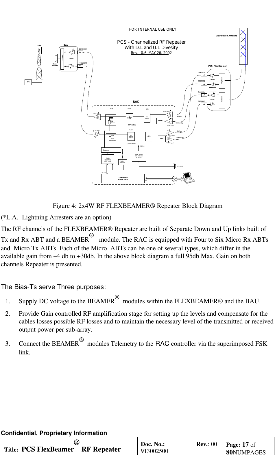

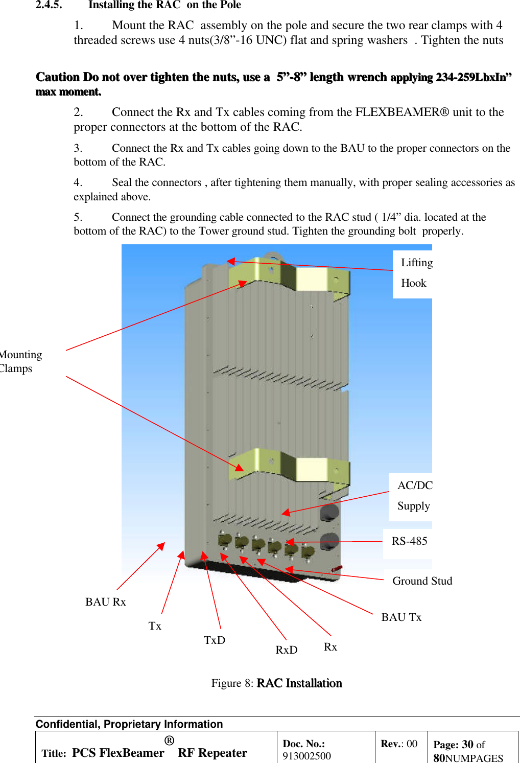
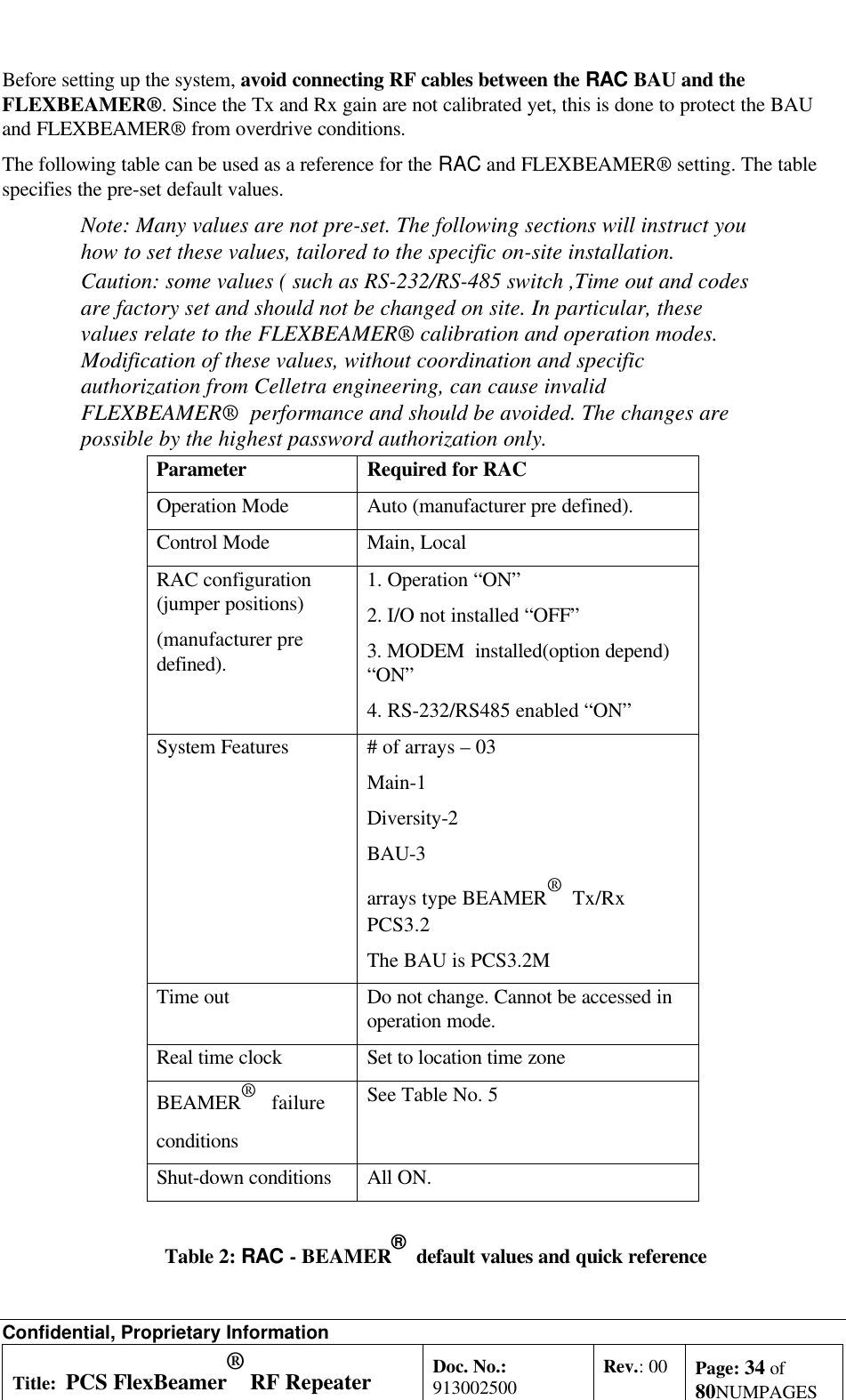
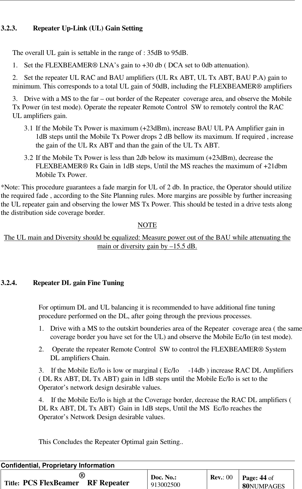
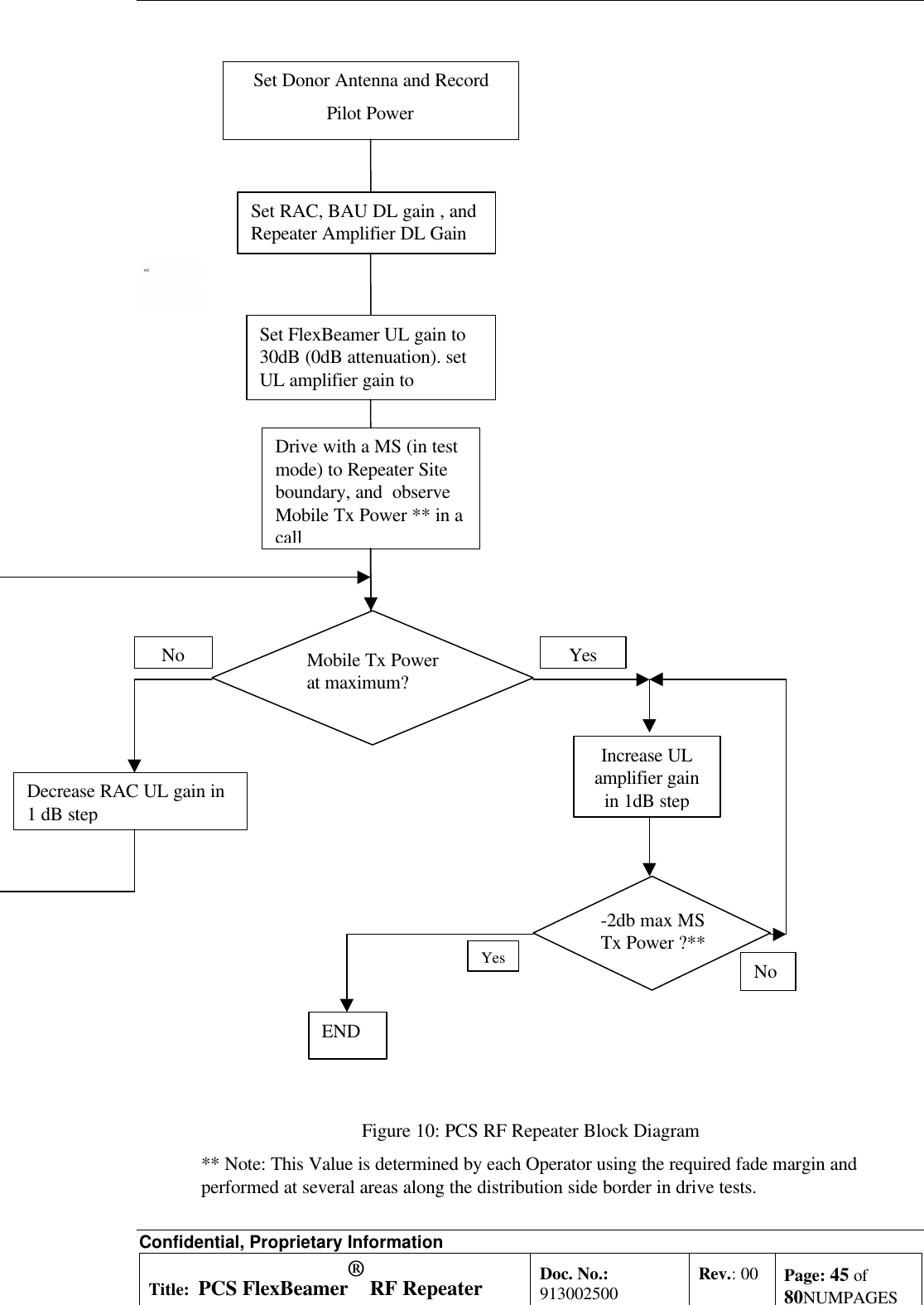
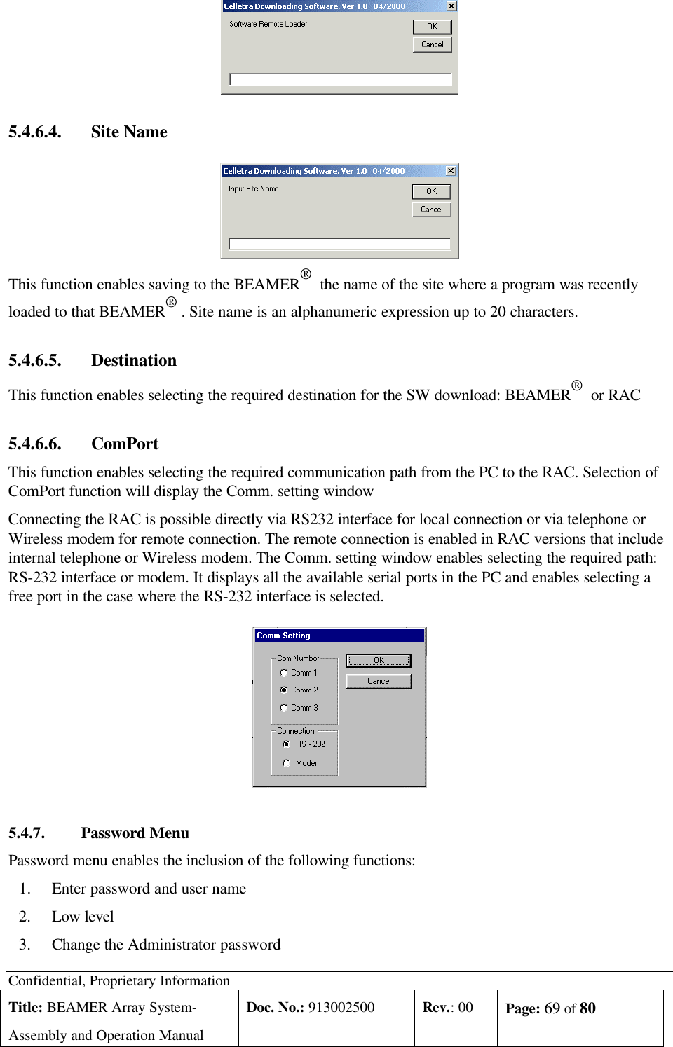
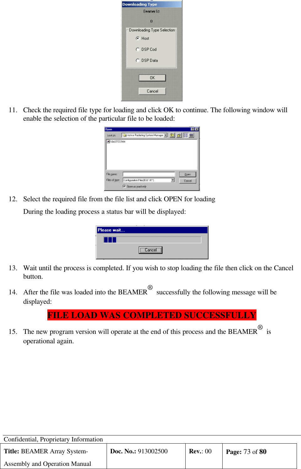
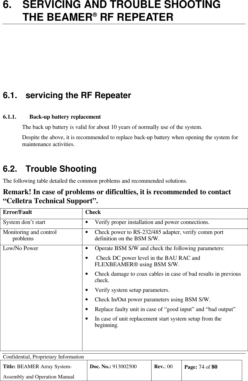
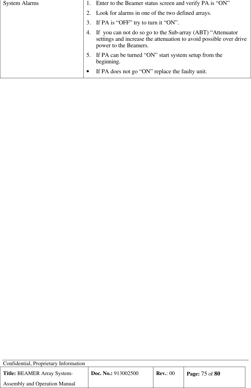
![Confidential, Proprietary InformationTitle: PCS FlexBeamer® RF RepeaterSystem A &O ManualDoc. No.:913002500 Rev.: 00 Page: 42 of80NUMPAGES3.2.1. Donor Antenna Setting1. Install the Repeater Donor Antenna and direct it optimally towards the Donor Sector.2. Connect a Pilot Scanner to the Donor Antenna port for verifying that the requested sector isrelayed.3. Record the maximum pilot signal level at the Donor Antenna terminal:• Pilot PN Sequence Offset: _________• Pilot power Pp _________[dBm]• Pilot quality Ec/Io: ____________[db]3.2.2. Repeater Down Link (DL) Gain SettingThe overall DL gain is settable in the rang of : 35dB to 95 dB by using the Remotely controlledAttenuators of the BAU, FLEXBEAMER® and RAC. The following procedure will define theoptimum DL gain setting.1. FLEXBEAMER® Gain SettingCalculate the required Pilot Power according to the normal Site Planning Procedure to betransmitted by the Repeater Array, according to the required coverage area, using the Networkplanning tools. Since the maximum FLEXBEAMER® total power is 8 (2x4) watts, the maximumallocated Pilot Power is 0.8 Watts (+29dBm) (20% of total power).The FLEXBEAMER® Gain is settable over a 15.5 dB range , in 0.5 dB steps.Denoting the required Pilot Power PP ( 2x0.8Watt) , the FLEXBEAMER® amplifier attenuatorshould be set to:FLEXBEAMER® Attenuation setting = 10 log 10 (PT max/10) =10 log 10 (PP/.10)[dB]……(1)When PT maxWattExample: Assume your Network Planning tool requires the Max. Pilot Power fromthe Distribution Array to be 1W. The FLEXBEAMER® attenuation should be setaccording to (1) to the following Value:FLEXBEAMER® Att. Value= 10 log10 (1/2.0)= -3.01 db ( rounded to 3db)](https://usermanual.wiki/Celletra/C-CPB/User-Guide-269279-Page-42.png)
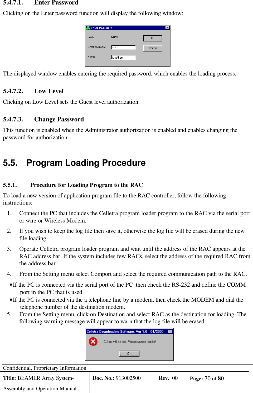
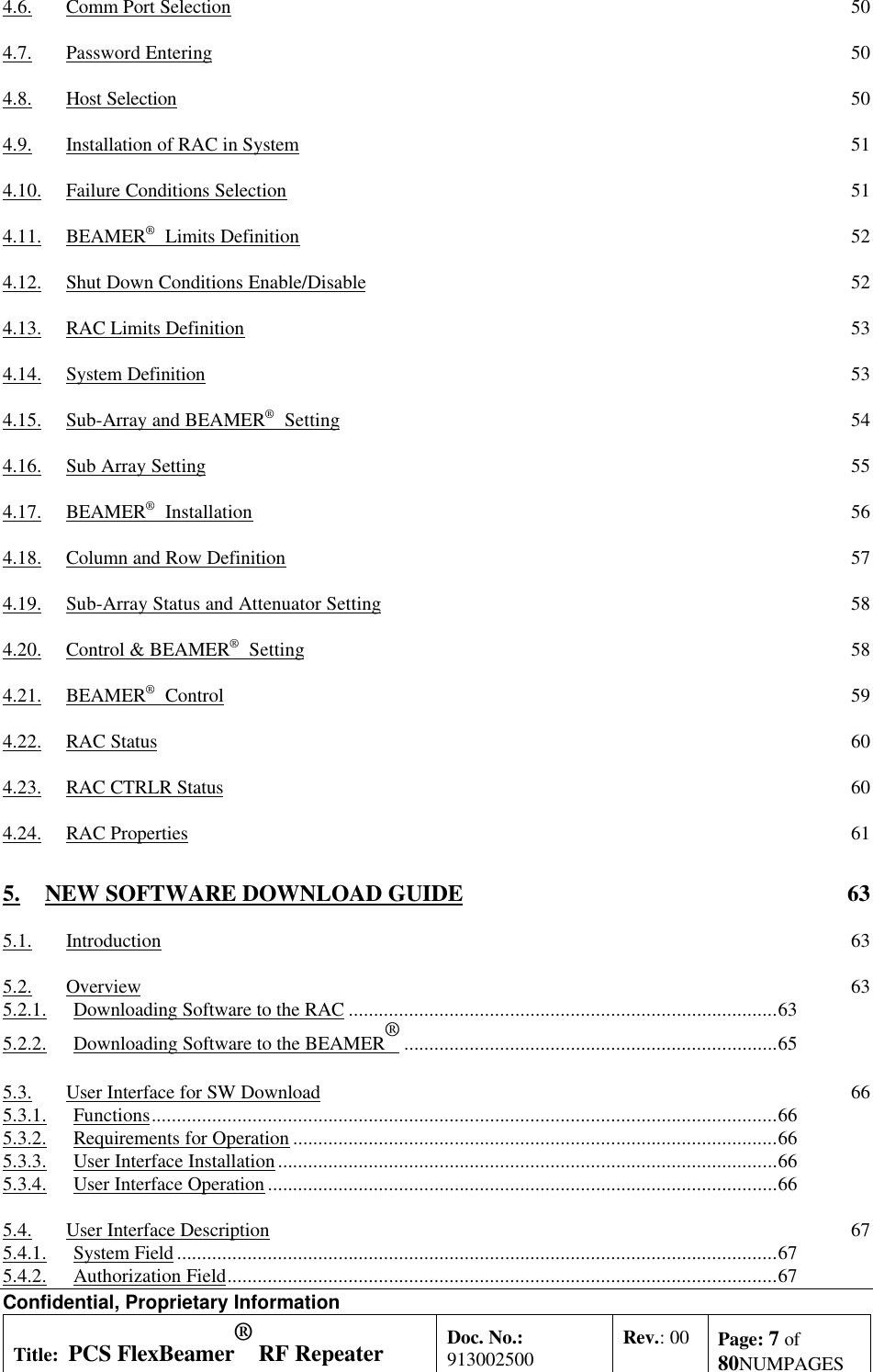
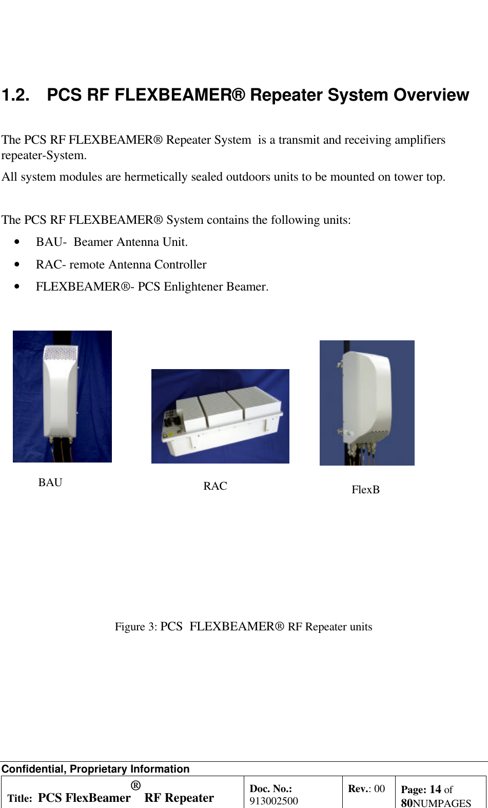
![Confidential, Proprietary InformationTitle: PCS FlexBeamer® RF RepeaterSystem A &O ManualDoc. No.:913002500 Rev.: 00 Page: 43 of80NUMPAGES2. DL Low Power Chain Gain Setting2.1 Calculating the Gain of the DL FLEXBEAMER® units: The Max. gain ofthe DL amplifiers in the RAC is 95 db. This gain amplification is composed of 4 successiveamplifiers- The BAU LNA, DL Rx ABT, the DL Tx ABT and the FLEXBEAMER® Beamer eachcontributes approximately 15dB of the total FLEXBEAMER® adjustable DL gain.The total gain of the DL Amplifiers of the RAC should be set to the value which will bring the PilotEc received at the Donor Antenna to the required value at the FLEXBEAMER® input. Thus theDL Gain of the Repeater System should be set to the following value:Total Gain of DL in Repeater = +Pp–P’p [dB]……………..(2)Where Pp denotes the DL signal input to the Donor Antenna ………….(3.1.1).Example:If the Pp measured at the Donor antenna is –60dbm, the total required gain ofthe DL amplifiers of the RAC is +27-(-60)=+87db ………..(2.1)2.2 Dividing the Gain between the FLEXBEAMER® Repeater stages: Aftercalculating the total DL gain of the FLEXBEAMER® Repeater per equation (2), the gain shouldbe divided between the 4 stages of the DL FLEXBEAMER® Repeater chain. following are therecommendations for doing that:a. Start the process by setting all the DCA attenuation in the BAU and RAC to15.5dB.b. Start reducing the Attenuation from max. at the BAU first(which is the firstamplifier in the chain.c. The second DCA to reduce the attenuation is the Rx ABT(second amplifier in thechain).d. The third DCA to be reduced it’s attenuation will be the Tx ABT.Example:According to the process in example (2.1) , one needs to have +71db gain outof the +95 db available. Following the steps a-c, the DL Tx ABT attenuator isset to 14dB attenuation, and the Rx ABT set to –10dB.NoteThe DL Main and Diversity EIRP’s should be equal in order to achieve themaximum diversity gain.Check by reducing the DL Diversity TX gain by –15.5 dB and check the power(actual or through the BSM indication) of the Main channel.Repeat the same procedure for the Diversity channel by reducing the Main TXchannel.](https://usermanual.wiki/Celletra/C-CPB/User-Guide-269279-Page-43.png)