Celletra C-UPB Single Channelized PCS Beamer Amplifier Unit User Manual users manual
Celletra Ltd. Single Channelized PCS Beamer Amplifier Unit users manual
Celletra >
users manual

Cellular Transmission Solutions
P.O. Box 106, Tavor building 1,
Yoqne'am Ilit 20692, ISRAEL
Tel. + 972 4 9592522
Fax. + 972 4 9592523
E-mail: celletra@celletra.com
Support: support@celletra.com
BEAMER®
PCS FLEXBEAMER® RF Repeater System
Assembly & Operation Manual
Document No. 913002500
Rev. 0.0
Name Date Signature
Written By N. David 7-5-2002
Checked Y.Gazit 9-5-2002
Checked G. Argaman
Approved M. Shalom
Cellular Transmission Solutions
P.O. Box 106, Tavor building 1,
Yoqne'am Ilit 20692, ISRAEL
Tel. + 972 4 9592522
Fax. + 972 4 9592523
E-mail: celletra@celletra.com
Support: support@celletra.com
Confidential, Proprietary Information
Title: PCS FlexBeamer® RF Repeater
System A &O Manual
Doc. No.: 913002500 Rev.: 00 Page: 2 of 84
FCC Part 15A Compliance Statement
This device complies with part 15 of the FCC rule
Operation is subject to the following two conditions: (1)
this device may not cause harmful interference , and (2)
this device must accept any interference received
including interference that may cause undesired operation
Caution
Changes or Modifications not expressly approved by Celletra Ltd
could void the user’s authority to operate the equipment”
NOTE
This equipment has been tested and found to comply with the limits
for a Class A digital device, pursuant to part 15 of the FCC rules
These limits are designed to provide reasonable protection against
harmful interference when the equipment is operated in a
commercial environment. This equipment generates, uses, and can
radiate Radio Frequency energy and, if not installed and used in
accordance with the instructions manual, may cause harmful
interference to radio communication. Operation of this equipment in
a residential area is likely to cause harmful interference in which
case the user will be required to correct the interference at his own
expense
For Customer and Technical Support contact
WWW.CELLETRA.COM or Email to Support@CELLETRA.COM

Cellular Transmission Solutions
P.O. Box 106, Tavor building 1,
Yoqne'am Ilit 20692, ISRAEL
Tel. + 972 4 9592522
Fax. + 972 4 9592523
E-mail: celletra@celletra.com
Support: support@celletra.com
Confidential, Proprietary Information
Title: PCS FlexBeamer® RF Repeater
System A &O Manual
Doc. No.: 913002500 Rev.: 00 Page: 3 of 84
Cellular Transmission Solutions
P.O. Box 106, Tavor building 1,
Yoqne'am Ilit 20692, ISRAEL
Tel. + 972 4 9592522
Fax. + 972 4 9592523
E-mail: celletra@celletra.com
Support: support@celletra.com
Confidential, Proprietary Information
Title: PCS FlexBeamer® RF Repeater
System A &O Manual
Doc. No.: 913002500 Rev.: 00 Page: 4 of 84
PROPRIETARY NOTICE
ALL DATA AND INFORMATION CONTAINED IN OR DISCLOSED BY THIS
DOCUMENT IS CONFIDENTIAL AND PROPRIETARY INFORMATION OF
CELLETRA LTD AND ALL RIGHTS THEREIN ARE EXPRESSLY
RESERVED. BY ACCEPTING THIS MATERIAL, THE RECIPIENT
AGREES THAT THIS MATERIAL AND THE INFORMATION CONTAINED
THEREIN IS HELD IN CONFIDENCE AND IN TRUST AND WILL NOT BE
USED, COPIED, REPRODUCED IN WHOLE OR IN PART. NOR ITS
CONTENTS REVEALED IN ANY MANNER TO OTHERS, WITHOUT THE
EXPLICIT WRITTEN PERMISSION OFCELLETRALTD.
Revision Description Date
0 Release May, 2002
1 Update July , 2002
Changes are periodically made to the information contained in this manual. These changes are published in the
"software/hardware release notes", and will be incorporated into new editions. All rights are reserved. No parts of this manual
may be reproduced in any form, without permission in writing from Celletra Ltd.
Copyright© 2002, Celletra Ltd.
BEAMER® is a trademark of Celletra Ltd.

Cellular Transmission Solutions
P.O. Box 106, Tavor building 1,
Yoqne'am Ilit 20692, ISRAEL
Tel. + 972 4 9592522
Fax. + 972 4 9592523
E-mail: celletra@celletra.com
Support: support@celletra.com
Confidential, Proprietary Information
Title: PCS FlexBeamer® RF Repeater
System A &O Manual
Doc. No.: 913002500 Rev.: 00 Page: 5 of 84
Celletra Ltd. reserves the right to change specifications without notice.

CONTENTS
Confidential, Proprietary Information
Title: PCS FlexBeamer® RF Repeater
System A &O Manual
Doc. No.: 913002500 Rev.: 00 Page: 6 of 84
CONTENTS
LIST OF FIGURES
LIST OF TABLES
LIST OF REFERENCES
1. PCS BEAMER® FLEXBEAMER® RF REPEATER SYSTEM DESCRIPTION 14
1.1. BEAMER® Module Concept 14
1.2. PCS RF FLEXBEAMER® Repeater System Overview 16
1.3. FLEXBEAMER® Repeater Overview 17
1.3.1. BAU...........................................................................................................................................................17
1.3.2. RAC...........................................................................................................................................................17
1.3.3. FLEXBEAMER® .....................................................................................................................................18
1.4. BEAMER® RF Repeater Modular Concept 21
1.5. Telemetry and M&C of the Repeater System 22
1.5.1. Network Architecture and Capacity.....................................................................................................22
1.5.2. Communication Procedure .....................................................................................................................22
1.5.3. BEAMER® Monitoring and Control..................................................................................................23
1.6. Power Distribution 24
2. RF REPEATER SYSTEM INSTALLATION GUIDE 25
2.1. Scope 25

CONTENTS
Confidential, Proprietary Information
Title: PCS FlexBeamer® RF Repeater
System A &O Manual
Doc. No.: 913002500 Rev.: 00 Page: 7 of 84
2.2. Important Safety Precautions 25
2.2.1. Handling and Moving the FLEXBEAMER® System Units..............................................................25
2.2.2. System Measurement and Testing Conditions...................................................................................27
2.3. BAU RAC and FLEXBEAMER® Installation Instructions 28
2.3.1. Sector Antenna Mounting.....................................................................................................................28
2.3.2. Donor Antenna Mounting.....................................................................................................................28
2.4. FLEXBEAMER® Installation Instructions 29
2.4.1. General Array Installation Instructions................................................................................................29
2.4.2. Unpacking.................................................................................................................................................29
2.4.3. Installing the FLEXBEAMER® Unit on the Pole : .............................................................................30
2.4.4. BAU Mounting........................................................................................................................................31
2.4.5. Installing the RAC on the Pole .............................................................................................................32
2.4.6. Dismounting the FLEXBEAMER® System units..............................................................................33
3. FLEXBEAMER® RF REPEATER SYSTEM SET-UP AND TUNING 34
3.1. FLEXBEAMER® RF Repeater System Set Up 34
3.1.1. AC Wiring.................................................................................................................................................34
3.1.2. Local or Remote PC Connection............................................................................................................35
3.1.3. System Configuration and Logical Setting..........................................................................................35
3.1.4. Setting the Bias-T Attenuation .............................................................................................................38
3.1.5. Coaxial Cables Connection.....................................................................................................................38
3.1.6. FLEXBEAMER® Configuration............................................................................................................38
3.1.7. Setting Limits, Failures and Shut-Down Conditions..........................................................................38
3.1.8. Changing the Real Time Clock...............................................................................................................42
3.1.9. FLEXBEAMER® System Sector Installation Record.......................................................................43
3.2. RF Repeater Tuning Procedure 44
3.2.1. Donor Antenna Setting ..........................................................................................................................45
3.2.2. Repeater Down Link (DL) Gain Setting ................................................................................................45
3.2.3. Repeater Up-Link (UL) Gain Setting .....................................................................................................47
3.2.4. Repeater DL gain Fine Tuning...............................................................................................................47
4. BSM (BEAMER® SYSTEM MANAGER) SOFWARE PROGRAM 50
4.1. Requirements for Operation 50
4.1.1. PC Hardware and operating System.....................................................................................................50
4.2. User Interface Description 50
4.2.1. Main Menu - BEAMER® (Active Radiating Module) System Manager......................................50
4.2.2. System Menu List....................................................................................................................................51
4.3. Status Reports 52
4.3.1. Report by Monitoring.............................................................................................................................52
4.3.2. BEAMER® RF Repeater System Control...........................................................................................52
4.4. BSM S/W 52
4.4.1. S/W Installation.......................................................................................................................................52
4.4.2. S/W Operation .........................................................................................................................................52
4.5. BSM Main Screen 53

CONTENTS
Confidential, Proprietary Information
Title: PCS FlexBeamer® RF Repeater
System A &O Manual
Doc. No.: 913002500 Rev.: 00 Page: 8 of 84
4.6. Comm Port Selection 54
4.7. Password Entering 54
4.8. Host Selection 54
4.9. Installation of RAC in System 55
4.10. Failure Conditions Selection 55
4.11. BEAMER® Limits Definition 56
4.12. Shut Down Conditions Enable/Disable 56
4.13. RAC Limits Definition 57
4.14. System Definition 57
4.15. Sub-Array and BEAMER® Setting 58
4.16. Sub Array Setting 59
4.17. BEAMER® Installation 60
4.18. Column and Row Definition 61
4.19. Sub-Array Status and Attenuator Setting 62
4.20. Control & BEAMER® Setting 62
4.21. BEAMER® Control 63
4.22. RAC Status 64
4.23. RAC CTRLR Status 64
4.24. RAC Properties 65
5. NEW SOFTWARE DOWNLOAD GUIDE 67
5.1. Introduction 67
5.2. Overview 67
5.2.1. Downloading Software to the RAC......................................................................................................67
5.2.2. Downloading Software to the BEAMER®..........................................................................................69
5.3. User Interface for SW Download 70
5.3.1. Functions..................................................................................................................................................70
5.3.2. Requirements for Operation...................................................................................................................70
5.3.3. User Interface Installation......................................................................................................................70
5.3.4. User Interface Operation........................................................................................................................71
5.4. User Interface Description 71
5.4.1. System Field .............................................................................................................................................71

CONTENTS
Confidential, Proprietary Information
Title: PCS FlexBeamer® RF Repeater
System A &O Manual
Doc. No.: 913002500 Rev.: 00 Page: 9 of 84
5.4.2. Authorization Field..................................................................................................................................71
5.4.3. System Date and Time Field...................................................................................................................71
5.4.4. RAC SW Properties Field .......................................................................................................................72
5.4.5. Destination Field......................................................................................................................................72
5.4.6. Setting Menu............................................................................................................................................72
5.4.7. Password Menu.......................................................................................................................................74
5.5. Program Loading Procedure 74
5.5.1. Procedure for Loading Program to the RAC........................................................................................74
5.6. Procedure for Loading Program to the BEAMER® 76
6. SERVICING AND TROUBLE SHOOTING THE BEAMER® RF REPEATER 78
6.1. servicing the RF Repeater 78
6.1.1. Back-up battery replacement .................................................................................................................78
6.2. Trouble Shooting 78
6.2.1. Troubleshooting the system using ICU log file..................................................................................80
6.2.1.1. Getting ICU Log File................................................................................................................................80
6.2.1.2. The Log file structure..............................................................................................................................80
WARRANTY
INDEX
List Of FIGURES
Figure 1: Repeater Simplified Block Diagram 14
Figure 2: BEAMER® block diagram 15
Figure 3: PCS FLEXBEAMER® RF Repeater units 16
Figure 4: 2x4W RF FLEXBEAMER® Repeater Block Diagram 19
Figure 5: Telemetry Communication procedure 22
Figure 6: F
FL
LE
EX
XB
BE
EA
AM
ME
ER
R®
®
I
In
ns
st
ta
al
ll
la
at
ti
io
on
n 30
Figure 8: BAU Installation 31
Figure 7: R
RA
AC
C
I
In
ns
st
ta
al
ll
la
at
ti
io
on
n 32
Figure 9: PCS RF Repeater Block Diagram 44
Figure 10: PCS RF Repeater Block Diagram 49

PCS BEAMER® FLEXBEAMER® RF Repeater System Description
Confidential, Proprietary Information
Title: PCS FlexBeamer® RF Repeater
System A &O Manual
Doc. No.: 913002500 Rev.: 00 Page: 11 of 84
List of TABLES
Table 1: RS485 communication connector 35
Table 2: RAC - BEAMER® default values and quick reference 37
Table 3: BEAMER® limits recommended settings 40
Table 4: RAC limits setting 40
Table 5: Failure conditions 41
Applicable Documents
Celletra Internal documents
1. C&M channel description dated 06.08.2000.
2. Micro Active Rx Bias-T Spec. Doc. No. 953000500
3. Micro Active Tx Bias-T Spec Doc. No. 953000400
4. Micro Active Diversity Unit for PCS Tx band Spec Doc. No. 811001300
5. PCS 1x4x4 Array Specifications, Doc. No. 953003200
6. PCS RF Channel Selective repeater system specifications, Doc. No. 952004100
7. PCS Beamer Rev. 2
8. PCS Beamer Rev. 2M
9. IS97D, IS95B

PCS BEAMER® FLEXBEAMER® RF Repeater System Description
Confidential, Proprietary Information
Title: PCS FlexBeamer® RF Repeater
System A &O Manual
Doc. No.: 913002500 Rev.: 00 Page: 12 of 84
Acronyms and Abbreviations
ACPR Adjacent Channel Power Ratio
BEAMER® Active Radiating Module
ATP Acceptance Tests Procedure
BAU BEAMER® Antenna Unit
BFN Beam Forming Network
BSM BEAMER® System Manager
BPF Band Pass Filter
BTS Base Transceiver Station
BW Band Width
CDMA Code Division Multiple Access
DCA Digitally Controlled Attenuator
DL Down Link
EMI Electro Magnetic Interference
FSK Frequency Shift Keying
RAC Interface & Control Unit
IM Inter Modulation
LED Light Emitting Diode
LSB Least Significant Bit
M&C Monitoring and Control
MSB Most Significant Bit
MTBF Mean Time Between Failures
MS Mobile Subscriber Unit
PCB Printed Circuit Board
RACC Remote antenna Converter Controller
RF Radio Frequency
RFI Radio Frequency Interference
RF RAC Radio Frequency Remote Antenna Controller
Rx Receiver
TBD To Be Defined
TDMA Time Division Multiple Access

PCS BEAMER® FLEXBEAMER® RF Repeater System Description
Confidential, Proprietary Information
Title: PCS FlexBeamer® RF Repeater
System A &O Manual
Doc. No.: 913002500 Rev.: 00 Page: 13 of 84
Tx Transmitter
VSWR Voltage Standing Wave Ratio
UL Up Link

PCS BEAMER® FLEXBEAMER® RF Repeater System Description
Confidential, Proprietary Information
Title: PCS FlexBeamer® RF Repeater
System A &O Manual
Doc. No.: 913002500 Rev.: 00 Page: 14 of 84
1. PCS BEAMER® FLEXBEAMER® RF
REPEATER SYSTEM DESCRIPTION
This document is a guide to the Installation, operation and maintenance of the PCS RF
FLEXBEAMER® System. This first chapter brings a brief description of the RF Repeater System
overview . PCS RF Channel Selective Repeater System consists of these Three parts:
• BAU (Beamer Antenna Unit) - the interface between the BTS (Base Transceiver Station) Via
the Donor Antenna and the RAC .
• RAC (Remote Antenna Controller)- Up link and Down link amplifiers with programmable
attenuators. Control card for C&M of the whole FLEXBEAMER® system.
• PCS FLEXBEAMER® (Coverage Enlightener BEAMER® - The main amplifier unit includes
two Beamers, dividers, combiners and a duplexer. This unit is connected to the sector antenna.
BAU RAC CEB
Donor
Antenna Distributing
Antenna
U.L
.
U.L
.
D.L
.
D.L
.
Figure 1: Repeater Simplified Block Diagram
1.1. BEAMER® Module Concept
The BEAMER® is an integrated active antenna for wireless communications. It incorporates a
transmission amplifier, Remote Controlled Gain, transmission band filter and the respective receive
chain: band filter, and Gain controlled LNA.
The Tx amplifier is linear. The Rx amplifier has an exceptional linear dynamic range. The integral unit
contains its own power conditioner and a monitoring and control circuit that communicates with the
RAC and from there on through the Wireless Modem to any remote PC (The Wireless Modem
feature is an option) . The whole unit is sealed and built as a plug-in replaceable unit. The design and
production techniques offer low price and high reliability.
PCS BEAMER® FLEXBEAMER® RF Repeater System Description
Confidential, Proprietary Information
Title: PCS FlexBeamer® RF Repeater
System A &O Manual
Doc. No.: 913002500 Rev.: 00 Page: 15 of 84
Band filter
Band filter
Micro-
Controller
Power
conditioner
PA
LNA
from BTS
to BTS
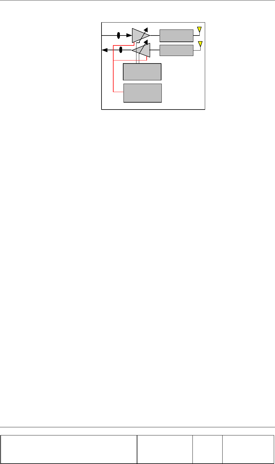
Figure 2: BEAMER® block diagram
The band pass filters (BPF) supply enough Tx/Rx channel isolation to ensure that the small amount of
Tx signal power and Tx wide band noise power leaking into the sensitive receive channel will not
degrade the Rx channel performance. In the FLEXBEAMER® System the BPF are replaced by a
duplexer and the Beamer antenna by a separate sector antenna.
The Rx amplifier is a low noise amplifier with a high enough intercept point that several PCS channels
received simultaneously should not degrade each other's performance. The low noise and high gain
performance of this amplifier compensate for the high losses of the coaxial cable going down from the
Rx BEAMER® front-end to the RAC and BAU and transmitted to the base station. The Tx
Amplifier is a power amplifier that enables up to 10 Watts average at the Tx antenna port. while
compensating for gain and power losses in the coaxial cable coming up from the BAU received from
the base station.
PCS BEAMER® FLEXBEAMER® RF Repeater System Description
Confidential, Proprietary Information
Title: PCS FlexBeamer® RF Repeater
System A &O Manual
Doc. No.: 913002500 Rev.: 00 Page: 16 of 84
1.2. PCS RF FLEXBEAMER® Repeater System Overview
The PCS RF FLEXBEAMER® Repeater System is a transmit and receiving amplifiers repeater-
System.
All system modules are hermetically sealed outdoors units to be mounted on tower top.
The PCS RF FLEXBEAMER® System contains the following units:
• BAU- Beamer Antenna Unit.
• RAC- remote Antenna Controller
• FLEXBEAMER®- PCS Enlightener Beamer.
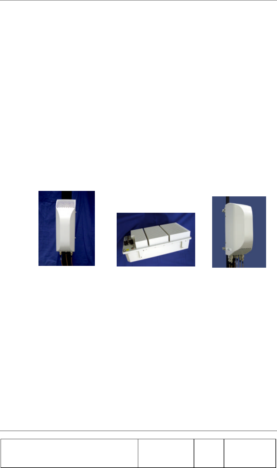
Figure 3: PCS FLEXBEAMER® RF Repeater units
BAU FlexB
eamer
RAC

PCS BEAMER® FLEXBEAMER® RF Repeater System Description
Confidential, Proprietary Information
Title: PCS FlexBeamer® RF Repeater
System A &O Manual
Doc. No.: 913002500 Rev.: 00 Page: 17 of 84
1.3. FLEXBEAMER® Repeater Overview
The FLEXBEAMER® Repeater System is installed outdoors on remote site tower top, close to the
Donor Side Antenna. The FLEXBEAMER® System contains the following units:
• BAU- Beamer Antenna Unit
• RAC- Remote Antenna Controller
• FLEXBEAMER®- Coverage Enlightener Beamer
1.3.1. BAU
Including:
• Duplexer
• Linear P.A (p/o Beamer®)
• LNA. (p/o Beamer®)
1.3.2. RAC
Including:
• RF band selective Filtration
• Rx ACBTs - Programmable gain UP LINK amplifiers, Bias-T
• Tx ACBTs - Programmable gain DOWN LINK amplifiers and Bias-T
• Control and Monitor (C&M) board for:
§ Local PC connection by RS-485 interface to supports software download and system
configuration via a PC and Software (S/W) packages (such as the BSM S/W for
local interface)
§ Remote interface options include Dial-up wireless modem (as an option).
• Internal 110-220AC power supply and power conditioning
The RAC is the RF interface between the FLEXBEAMER® unit and the BAU, provides the
BEAMER® units in the BAU and the FLEXBEAMER® with the DC power, and control each
individual BEAMER®. It consists of a set of Bias T connections for multiplexing the RF, DC power
and the C&M communication on the RF cables to the BEAMER® units in the BAU and
FLEXBEAMER® units, a modem for communicating with each of the BEAMER® units, and a digital
processor/controller.

PCS BEAMER® FLEXBEAMER® RF Repeater System Description
Confidential, Proprietary Information
Title: PCS FlexBeamer® RF Repeater
System A &O Manual
Doc. No.: 913002500 Rev.: 00 Page: 18 of 84
The RAC interfaces to the Tx and Rx RF signals from the BTS via the Donor antenna and the BAU
has two serial ports for a local host computer RS-485 and remote control via a wireless modem for
diagnostics, (as an option) monitoring and control. The Active Bias-Ts in the RAC enable setting the
proper input power for the BEAMER® units and maintaining beam shaping using the DCA inside
the Active Bias-Ts. Up to 6 ACBTs , in any combination of Rx and Tx types can be assembled in
each RAC.
The RAC controller monitors the proper operation of the BEAMER® units of the BAU and
FLEXBEAMER® and enables real-time bi-directional communication between individual BEAMER®
unit and dedicated computer, via the RAC. The BEAMER® modules are constantly monitored and
controlled by the RAC unit.
Bi-directional communication with the BEAMER® is established through an FSK modulated
communication channel multiplexed on the Rx coaxial cable connecting the individual BEAMER® to
the RAC. The coaxial cable can be as long as 100 meters and have losses of up to 8db at 1850 to
1945MHz band.
The Uplink signal at 1850-1865 MHz runs on the same coaxial (Rx)cable with DC and the M&C from the
FLEXBEAMER®, but an isolation between the DC, M&C, and Uplink signals is high due to Bias-T
isolation.
The Down Link signal at 1930-1945 MHz runs on the same coaxial (Tx) cable together with the DC
voltage, but isolation between the DC voltage and Tx signals is high due to Bias-T isolation.
1.3.3. FLEXBEAMER®
Including:
• Linear P.A and LNA (Beamer®)
• Duplexer
• Combiners and Dividers
• Active Diversity Units for Up link or Down link or both Diversities (Optional).
PCS BEAMER® FLEXBEAMER® RF Repeater System Description
Confidential, Proprietary Information
Title: PCS FlexBeamer® RF Repeater
System A &O Manual
Doc. No.: 913002500 Rev.: 00 Page: 19 of 84
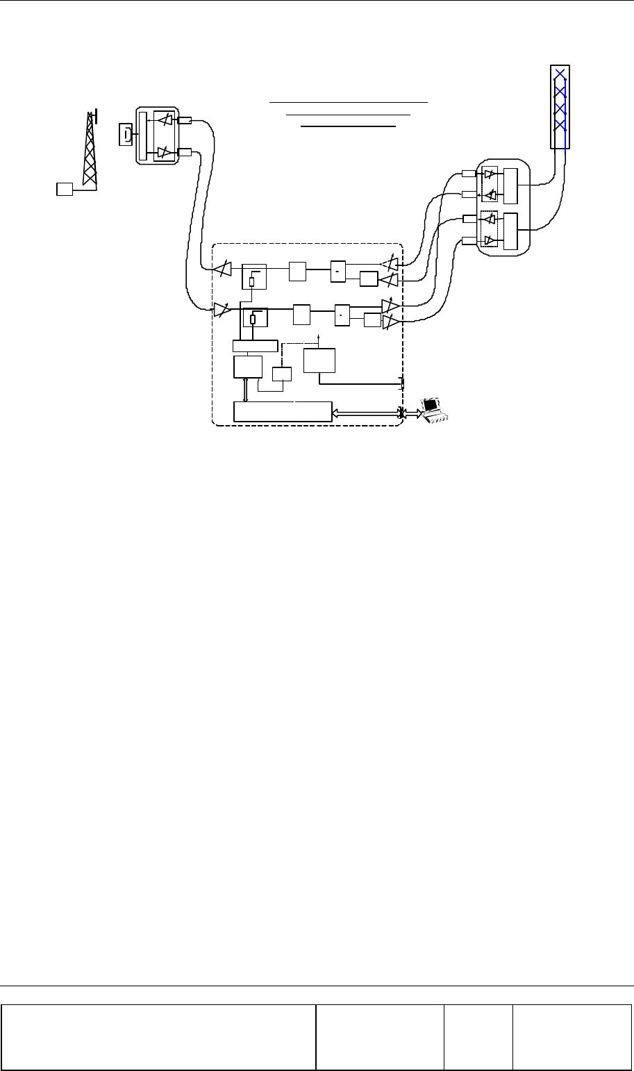
Distribution Antenna
BEAMER
L.A
L.A
L.A
L.A
PCS FlexBeamer
L.A
Donor
Antenna
BAU
Duplexer
RAC
BTS
Tx/Rx
FOR INTERNAL USE ONLY
PCS - Channelized RF Repeater
With D.L and U.L Divesity
Rev. :0.6 MAY 26, 2002
BEAMER
BEAMER
L.A
Duplexer Duplexer
2690002
2690002
2690002
2690002
2690002
2690002
Lap Top
Duplexer
CDMA
PCS phone
(QCP-1960)
Control Card
ICU OR MPIB
Power Supply
220 110 VAC
to 24VDC
220 / 110 VAC
24VDC
RS-485
RS-232
ABT Tx- TypeC
ABT Rx-Type B
UL Main
UL Diversity
DL Main
DL Diversity
Battery
Charger
ABT Rx-Type B
ABT Tx-Type C
Attenuator
Attenuator
ABT Tx-Type C
ABT Tx- Type A
UP-LINK
PMDU
ADU
DOWN-LINK
17 3
3
17
17
-6
-0.5 +22 -3.5
20dB
30dB
20dB
30dB
UL
CHANNEL
FILTER
1:2
DIVIDER
DL
CHANNEL
FILTER
1:2
DIVIDER
+22
Figure 4: 2x4W RF FLEXBEAMER® Repeater Block Diagram
(*L.A.- Lightning Arresters are an option)
The RF channels of the FLEXBEAMER® Repeater are built of Separate Down and Up links built of
Tx and Rx ABT and a BEAMER® module. The RAC is equipped with Four to Six Micro Rx ABTs
and Micro Tx ABTs. Each of the Micro ABTs can be one of several types, which differ in the
available gain from –4 db to +30db. In the above block diagram a full 95db Max. Gain on both channels
Repeater is presented.
The Bias-Ts serve Three purposes:
1. Supply DC voltage to the BEAMER® modules within the FLEXBEAMER® and the BAU.
2. Provide Gain controlled RF amplification stage for setting up the levels and compensate for the
cables losses possible RF losses and to maintain the necessary level of the transmitted or
received output power per sub-array.
3. Connect the BEAMER® modules Telemetry to the RAC controller via the superimposed FSK
link.

PCS BEAMER® FLEXBEAMER® RF Repeater System Description
Confidential, Proprietary Information
Title: PCS FlexBeamer® RF Repeater
System A &O Manual
Doc. No.: 913002500 Rev.: 00 Page: 20 of 84
The gain of the Bias-Ts is defined according to the system design.
The Active Bias-T comprised of a boost amplifier and a digital controlled attenuator in order to adjust
the gain and enable a convenient interface to the Control features. The gain of the ABT assemblies is
Temperature Compensated.
The Rx ABTs are transparent to the FSK communication channel which enables the M&C
communication with the BEAMER® units in the FLEXBEAMER® and the BAU.
In this manual, Bias-Ts are also termed 'sub-array', since each Bias-T can serves an independent
portion of an array (i.e., Tx sub-array or Rx1 and Rx2 sub-arrays, which are all physically part of the
same array, but are logically independent entities).

PCS BEAMER® FLEXBEAMER® RF Repeater System Description
Confidential, Proprietary Information
Title: PCS FlexBeamer® RF Repeater
System A &O Manual
Doc. No.: 913002500 Rev.: 00 Page: 21 of 84
1.4. BEAMER® RF Repeater Modular Concept
The BEAMER® RF REPEATER product family is built in a modular way, enabling Celletra to
optimize the RF repeater performance /price to the specific needs of each customer and application.
This document specifies a unique PCS RF REPEATER BEAMER® system with the following
properties:
• Single , Vertically Polarized high gain Donor Antenna
• High power Donor Uplink Amplifier for far remote RF Repeater applications.
• Up to 95db gain on each link with 60 db remotely controlled Gain Control
• Single CDMA Channelizing narrow band filter on both the Up and Down links
• RF Band Selective Filters on both the Donor Side and Distribution side.
• Active Beamer BAU module on the Donor Side with :
o +23dbm Average Composite Up Link Power
o 30dB gain.
o >+17 dBi Donor Antenna.
o +46dbm EIRP (Effective isotropic Radiated Power)
• Active Beamer® FLEXBEAMER® on the Distribution Side with :
o 2x+35dBm Output power at the antenna port for one channel.
o 40dB gain
o CDMA ACPR as per IS-95.
o Lightning Arrester on Coaxial Cables.(option)
• +24VDC to supply the whole system or 110/220V AC to +24VDC Power Supply
(Optional).
• Wireless CDMA dialup Modem for remote M&C Capabilities.

PCS BEAMER® FLEXBEAMER® RF Repeater System Description
Confidential, Proprietary Information
Title: PCS FlexBeamer® RF Repeater
System A &O Manual
Doc. No.: 913002500 Rev.: 00 Page: 22 of 84
1.5. Telemetry and M&C of the Repeater System
1.5.1. Network Architecture and Capacity
The RAC is the master in a star configured network .The Telemetry network enables data
transmission along the following data transmission paths:
1. RAC to each BEAMER® unit of any 2 BEAMER® FLEXBEAMER® and BAU
BEAMER®.
2. RAC to PC Locally Connected (or via Wireless Modem as an option)
3. BEAMER® to RAC
The maximum capacity of the network is 16 BEAMER® modules in a FLEXBEAMER® and BAU.
The actual communication with the RAC and BEAMER® FLEXBEAMER® or BAU is done by
the BSM SW Package running on local or remote PC.
1.5.2. Communication Procedure
The communication mode between the RAC, the BEAMER® , and the PC is half-duplex. The
communication procedure is described in the following figure:
PC ICU BEAMER #1
SEND DATA
COMMANDS
COMMANDS
STATUS
STATUS
SEND DATA
BEAMER #2 BEAMER#16
COMMANDS
STATUS
COMMANDS
STATUS
COMMANDS
STATUS
Figure 5: Telemetry Communication procedure

PCS BEAMER® FLEXBEAMER® RF Repeater System Description
Confidential, Proprietary Information
Title: PCS FlexBeamer® RF Repeater
System A &O Manual
Doc. No.: 913002500 Rev.: 00 Page: 23 of 84
1.5.3. BEAMER® Monitoring and Control
Monitoring and control (M&C) of the whole RF Repeater is performed from the RAC by
the internal Control Card. The Control card of the RAC has several internal communication
channels and some external channels.
Internal Communication Channels:
• FSK modulated signal to control the Beamer FLEXBEAMER® or BAU Beamer units.
• Parallel TTL Level lines to control the ABTs of the RAC.
External Communication Channels:
• RS485 through an external connector to BSM operated Local PC
• RS232 through the Wireless Modem to the CDMA network and remote BSM
operated PC.
The M&C system will monitor and control the following functions, when the Failure
definitions are fully programmable via MMI and NMS.:
• C&M functions for the BEAMER® module in FLEXBEAMER® or BAU via FSK
channel includes continuous detection of each BEAMER module status and Query of
selected BEAMER® module selected parameters . These include:
Ø For the P.A half of the BEAMER® module:
• Input power measurement -
• Output Power measurement
• Temperature measurement
• Tx current consumption
• Tx return power alarm
• Input voltage
• Tx gain control
• Tx Phase control
• Automatic shut down
Ø For the LNA half of the BEAMER® module:
• Rx current consumption
• Rx gain control.

PCS BEAMER® FLEXBEAMER® RF Repeater System Description
Confidential, Proprietary Information
Title: PCS FlexBeamer® RF Repeater
System A &O Manual
Doc. No.: 913002500 Rev.: 00 Page: 24 of 84
• Rx Phase control
• CTRLR status
• Manual control of selected BEAMER® PA ON/OFF state and DCA
Attenuation values.
• Control ABTs Gain states
• Monitor ABTs amplifiers well being by monitoring the ABTs currents.
• Checks the +24V internal Supply.
• Software upgrade Download into a selected BEAMER® module and the Control
Card Remotely
• Faults indication Register which saves the Fault Indications History to be read remotely
when required.
1.6. Power Distribution
The Repeater System is powered by connecting the AC power supply line to the AC connections in
the panel of the RAC. DC voltage is supplied via the Tx and Rx coaxial cable coming up from the
RAC to the FLEXBEAMER® and BAU for system operation.
Power Source 110/220VAC or +24VDC up to 400Watt
ACBT Max. Current
Consumption Up to 200mA @ +24VDC with no FLEXBEAMER® or BAU
connected (DC)
Max. Current per BEAMER®
Ver.3.2 (in FLEXBEAMER®)
Up to 3Amp. @ +24VDC
Max. Current per BEAMER®
Ver.3.2 M (in BAU)
Up to 1Amp. @ +24VDC
RAC Connectors
Tx Connector to FLEXBEAMER® unit N-type connector, female
Tx/Rx Connection to BAU N-type connector, female
Rx Connector to FLEXBEAMER® unit N-type connector, female
RS-485 connector Amphenol 7 pins female sealed connector
AC/DC Connector Amphenol 7 pins male sealed connector
Grounding Connection By physically Wiring the RAC to pole grounding

RF Repeater System INSTALLATION GUIDE
Confidential, Proprietary Information
Title: PCS FlexBeamer® RF Repeater
System A &O Manual
Doc. No.: 913002500 Rev.: 00 Page: 25 of 84
2. RF REPEATER SYSTEM
INSTALLATION GUIDE
2.1. Scope
This chapter describes the installation of the PCS FLEXBEAMER® RF Repeater System and its
integration into the PCS Network by properly setting up the Repeater parameters .
The FLEXBEAMER® RF Repeater System is basically a modular tower top Repeater with the
FLEXBEAMER® Sector Active unit at the Distribution side of the Repeater and the BAU and RAC,
being assembled near the Donor Antenna , includes the Donor Side LNA , Donor Side Power amplifier
and all the Telemetry , Monitoring and Control ( Including the Wireless Modem as an option). The
FLEXBEAMER® RF Repeater is equipped with programming and modularity features that are
uncommon with other, comparable systems.
The chapter details the instructions for field installation of the FLEXBEAMER® RF Repeater system.
It is intended to be used by customer technical personnel, who are trained to install and service the
FLEXBEAMER® RF Repeater system.
2.2. Important Safety Precautions
The system is supplied following extensive acceptance production line tests. Usually, lab tests will not
be required before installing the unit at the customer's location. One should always be aware of the
necessary safety precautions, assuring that the FLEXBEAMER® Repeater system will be fully
functional after the installation.
Read this instruction guide thoroughly before starting with the installation. In case of doubt, do not
hesitate to call Celletra Customer Support engineering. Celletra Customer Support contact points are
given at :
WWW.CELLETRA.COM or Email to Support@CELLETRA.COM
2.2.1. Handling and Moving the FLEXBEAMER® System Units
The FLEXBEAMER®, BAU and the RAC are delicate and accurate electrical apparatus.
• Use extreme caution when handling the units. Always use the original box, with proper
padding, when delivering or moving the FLEXBEAMER® system units.
• The FLEXBEAMER® overall unit weight is ~12kg. If necessary, each unit should be carefully
carried by one person. When there is a need to hang a unit to bring it up the tower, use the
hangers for that purpose. (Shown in the mechanical drawings).

RF Repeater System INSTALLATION GUIDE
Confidential, Proprietary Information
Title: PCS FlexBeamer® RF Repeater
System A &O Manual
Doc. No.: 913002500 Rev.: 00 Page: 26 of 84
• The RAC module overall weight is 12 Kg. The RAC can be carried by one person .
For lifting it up the RAC up tower, use the clamps mechanical base units.
• The RAC Module is Hermetically sealed in controlled environment. Do not open any
of the covers or disassemble the BEAMER® units attached to it. This should be
done only in a controlled environment by Celletra authorized Personnel.
• The FLEXBEAMER® module overall weight is 8 Kg FLEXBEAMER® hardware is
hermetically sealed in controlled environment. Do not open or try to disassemble a
BEAMER® module. This should be done only by Celletra authorized personnel.
BEAMER® modules can be replaced by authorized personnel only following the
instruction herein.
• Use extra caution when installing the unit on tower top. Use proper winch or pulley to
lift the unit up the tower. Watch carefully for possible obstacles when lifting the units.
Pad the units, if needed, to avoid possible damage during lift-up.
• Always shut down the AC or DC supply to the RAC before replacing or removing
the FLEXBEAMER® or BAU from the tower.

RF Repeater System INSTALLATION GUIDE
Confidential, Proprietary Information
Title: PCS FlexBeamer® RF Repeater
System A &O Manual
Doc. No.: 913002500 Rev.: 00 Page: 27 of 84
2.2.2. System Measurement and Testing Conditions
• Live +24VDC with high current capability exists on the FLEXBEAMER® and BAU Coaxial
connections of the RAC. (These are the Tx ABT output and the Rx ABT input N-type
connectors at the RAC). Disconnect the AC or DC power to the RAC before any cable is
disconnected from the RAC, FLEXBEAMER® or BAU.
• Always use a DC block device connected to the measuring equipment input or output ports
(spectrum analyzer, power meter, or RF signal source), when measuring RAC performance.
• Do not apply more than +10dBm of RF input power to any RF port of the
FLEXBEAMER® Repeater system, or irreversible damage may occur.
• When measuring high power outputs, always verify that the equipment input port is capable for
handling the expected output power.
• When testing the units in lab or during field installation, always practice RF
radiation safety rules. It is not recommended for service or lab personnel to
work closer then 2 meters away from the FLEXBEAMER® Antenna surface
when operated at full RF power.
• During lab tests, with AC voltage applied to the RAC, do not use any PCS mobile transmitter
in a range of less than 10 meters from the FLEXBEAMER® unit. An unexpectedly high RF
power might appear at the output ports, which might in turn damage the measuring equipment
connected to that port.

RF Repeater System INSTALLATION GUIDE
Confidential, Proprietary Information
Title: PCS FlexBeamer® RF Repeater
System A &O Manual
Doc. No.: 913002500 Rev.: 00 Page: 28 of 84
2.3. BAU RAC and FLEXBEAMER® Installation Instructions
2.3.1. Sector Antenna Mounting
The Sector Antenna should be mounted on the top of the tower in order to achive best
coverage. The Customer should refer to existing Network Planning Tools or Celletra Technical
Support.
2.3.2. Donor Antenna Mounting
1. The mounting of the Donor antenna is pending the application and the location specific
parameters. The following guide lines for the Donor antenna mounting are recommendations
and the Customer should refer to existing Network Planning Tools or Celletra Technical
Support.:
• The Donor Antenna and the distribution antenna have Isolation in between them of at
least 10 db higher then the overall Repeater Gain. Since Gain is 35 to 95db , the
isolation should be 45 to 105 db. The Isolation is achieved by mounting the two
Antennas and the FLEXBEAMER® on opposite walls of a building or by mounting
both on the same tower but up to 10 meters vertically separation ( Isolation
dependent).
• For Maximum Repeater Coverage the Distribution FLEXBEAMER® antenna will be
mounted on Tower top while the Donor antenna will be mounted up to 10 meters
below the FLEXBEAMER® antenna.
2. The Donor antenna is a high Gain, high directivity, low side lobes Antenna and can be
one of several types and different vendors. Mount the Donor antenna following strictly the
manufacturer instructions.
3. Trim the Donor antenna Azimuth towards the Donor Base Station ,as per the process
of paragraph 3.2.1. Tighten and secure all screws per the Antenna Vendor instructions.

RF Repeater System INSTALLATION GUIDE
Confidential, Proprietary Information
Title: PCS FlexBeamer® RF Repeater
System A &O Manual
Doc. No.: 913002500 Rev.: 00 Page: 29 of 84
2.4. FLEXBEAMER® Installation Instructions
2.4.1. General Array Installation Instructions
We recommend using a 3”-4.5” diameter pole for the FLEXBEAMER® System installation. The
figures later in this section illustrate the installed FLEXBEAMER® units, showing the Tx and Rx
cables connections.
The RF coaxial cables connecting the BAU FLEXBEAMER® and the RAC can be of any 3/8” or ½”
diameter low loss type. These cables carry DC Current and RF signals from the RAC to the BAU and
FLEXBEAMER®. Since the FLEXBEAMER® include the Power amplifier and the LNA, the losses
on these cables can be high without affecting the overall performance. Thus , these cables can be as
long as 100 meters .
Sealing and weatherproofing of RF connector is of prime importance to assure good electrical contact
for many years, minimizing DC loss and passive RF inter-modulation effects. Thus, special care should
be taken with the RF connectors sealing and weatherproofing especially at the FLEXBEAMER® input
connectors that are exposed to extreme environmental conditions. Common sealing practice should be
used.
For sealing instructions, refer, for example, to Andrews weatherproofing recommendations with 3MTM
Cold ShrinkTM Weatherproofing Kit, or an equivalent sealing method.
Before installing the FLEXBEAMER® unit, note that each FLEXBEAMER® and BAU has a Tag
attached to it. After installation remove the tag keep it and log this info in the system manual book. This
tag carries the BEAMER® modules address.(This address is the serial number of each BEAMER®
unit as appears on the module label nearby the Rx connector).You will need these IDs later, for system
configuration setup.
2.4.2. Unpacking
Unpack the units and verify that there are no mechanical damages to any of the parts of the
FLEXBEAMER® units.
RF Repeater System INSTALLATION GUIDE
Confidential, Proprietary Information
Title: PCS FlexBeamer® RF Repeater
System A &O Manual
Doc. No.: 913002500 Rev.: 00 Page: 30 of 84
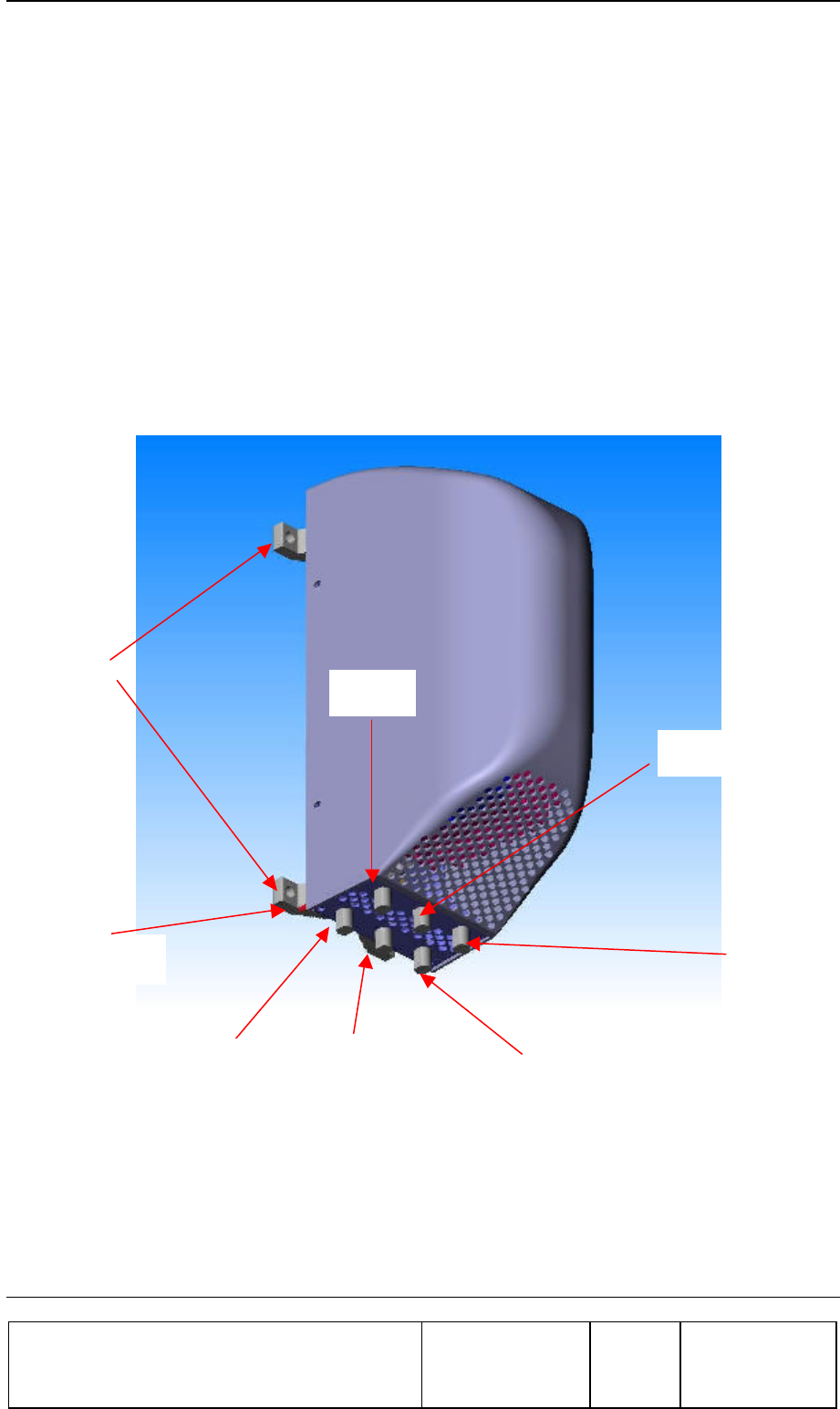
2.4.3. Installing the FLEXBEAMER® Unit on the Pole :
1. Position the FLEXBEAMER® unit on the pole so that it is aligned to the desired
direction according to network management instructions. Tighten the 4 nuts use flat and
spring washers (3/8”-16 UNC) using a 9/16” wrench.
2. Connect the Sector Antenna cables coming from the top tower antenna.
3. Install the Lightning protectors if needed and Connect the Tx and Rx cables going down
to the RAC unit.
C
Ca
au
ut
ti
io
on
n
-
-
D
Do
o
n
no
ot
t
o
ov
ve
er
r
t
ti
ig
gh
ht
te
en
n
t
th
he
e
n
nu
ut
ts
s,
,
u
us
se
e
a
a
5
5”
”-
-8
8”
”
l
le
en
ng
gt
th
h
w
wr
re
en
nc
ch
h
a
ap
pp
pl
ly
yi
in
ng
g
2
23
34
4-
-2
25
59
9
L
Lb
bx
xI
In
n”
”
m
ma
ax
x
m
mo
om
me
en
nt
t
.
.
Figure 6: F
FL
LE
EX
XB
BE
EA
AM
ME
ER
R®
®
I
In
ns
st
ta
al
ll
la
at
ti
io
on
n
Antenna 1
Rx 1
Tx 1
Ground Stud
Mounting
Clamps
Antenna 2
Rx 2
Tx 2
RF Repeater System INSTALLATION GUIDE
Confidential, Proprietary Information
Title: PCS FlexBeamer® RF Repeater
System A &O Manual
Doc. No.: 913002500 Rev.: 00 Page: 31 of 84
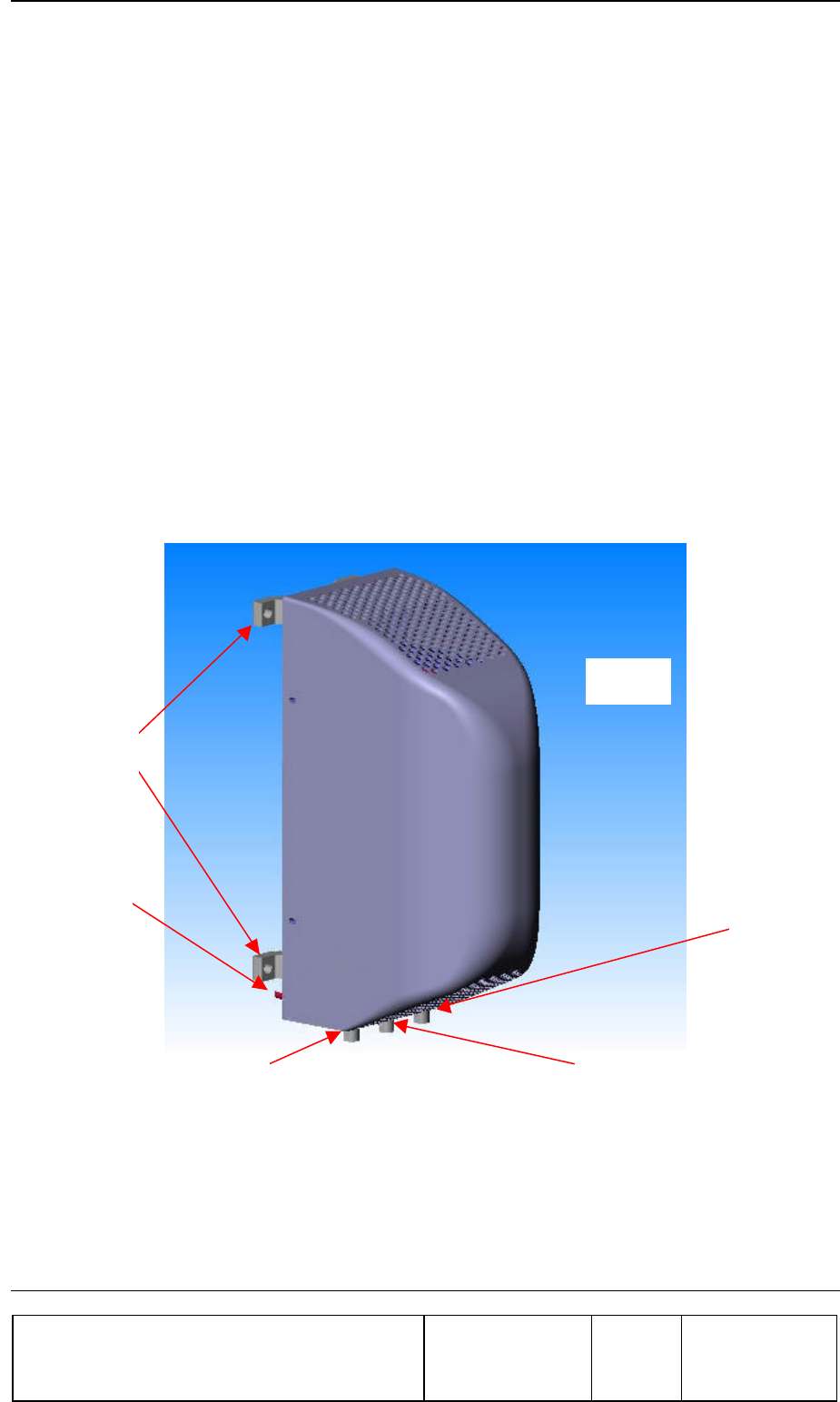
2.4.4. BAU Mounting
1. The BAU should be mounted near the Donor antenna on the mast. The cable
connecting between the BAU and the Donor antenna is preset to 2.5 meters max. in
order to achieve an overall lowest Noise Figure possible on the Down link .
2. Install the BAU unit on the Pole verify that the distance between the BAU and the
RAC will be greater then 10 meters in order to provide good isolation between input
and output of the repeater.
3. Mount the BAU assembly on the pole and secure the two rear clamps with 4
threaded screws and 4 nuts(3/8”-16 UNC), flat and spring washers . Tighten the
nuts using a 9/16” wrench.
4. Connect the grounding cable connected to the BAU stud ( 1/4” dia. located at the
bottom of the BAU) to the Tower ground stud. Tighten the grounding bolt properly
C
Ca
au
ut
ti
io
on
n
D
Do
o
n
no
ot
t
o
ov
ve
er
r
t
ti
ig
gh
ht
te
en
n
t
th
he
e
n
nu
ut
ts
s,
,
u
us
se
e
a
a
5
5”
”-
-8
8”
”
l
le
en
ng
gt
th
h
w
wr
re
en
nc
ch
h
a
ap
pp
pl
ly
yi
in
ng
g
2
23
34
4-
-
2
25
59
9L
Lb
bx
xI
In
n”
”
m
ma
ax
x
m
mo
om
me
en
nt
t.
.
Figure 7: BAU Installation
Rx
Mounting
Clamps
Antenna
Ground Stud
Tx
RF Repeater System INSTALLATION GUIDE
Confidential, Proprietary Information
Title: PCS FlexBeamer® RF Repeater
System A &O Manual
Doc. No.: 913002500 Rev.: 00 Page: 32 of 84
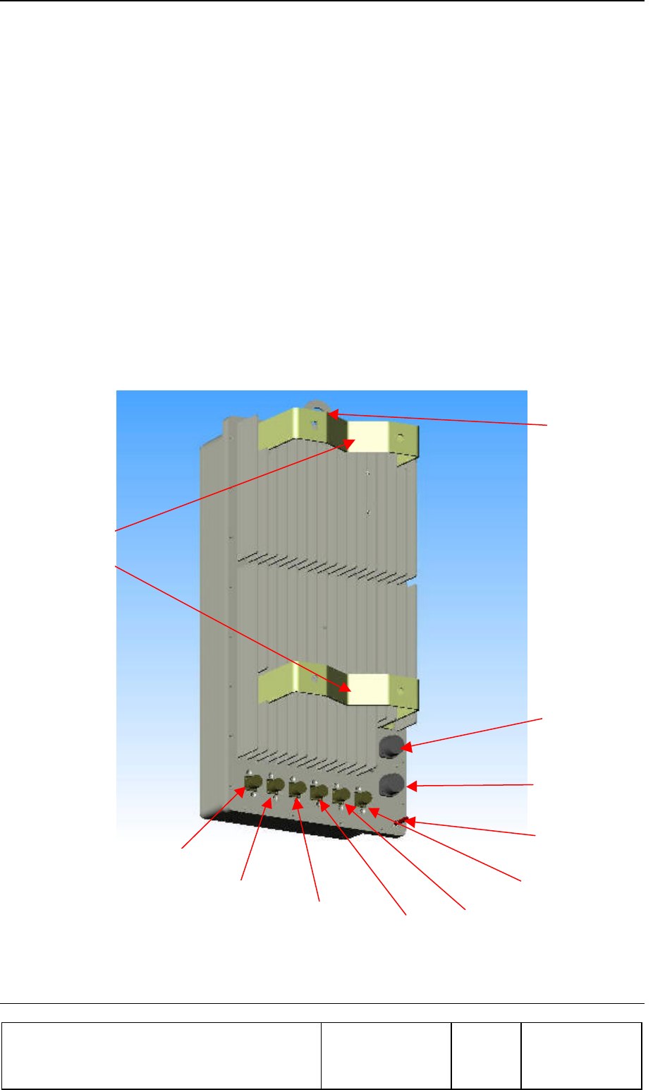
2.4.5. Installing the RAC on the Pole
1. Mount the RAC assembly on the pole and secure the two rear clamps with 4
threaded screws use 4 nuts(3/8”-16 UNC) flat and spring washers . Tighten the nuts using a
9/16” wrench.
C
Ca
au
ut
ti
io
on
n
D
Do
o
n
no
ot
t
o
ov
ve
er
r
t
ti
ig
gh
ht
te
en
n
t
th
he
e
n
nu
ut
ts
s,
,
u
us
se
e
a
a
5
5”
”-
-8
8”
”
l
le
en
ng
gt
th
h
w
wr
re
en
nc
ch
h
a
ap
pp
pl
ly
yi
in
ng
g
2
23
34
4-
-2
25
59
9L
Lb
bx
xI
In
n”
”
m
ma
ax
x
m
mo
om
me
en
nt
t.
.
2. Connect the Rx and Tx cables coming from the FLEXBEAMER® unit to the proper
connectors at the bottom of the RAC.
3. Connect the Rx and Tx cables going down to the BAU to the proper connectors on the
bottom of the RAC.
4. Seal the connectors , after tightening them manually, with proper sealing accessories
as explained above.
5. Connect the grounding cable connected to the RAC stud ( 1/4” dia. located at the
bottom of the RAC) to the Tower ground stud. Tighten the grounding bolt properly.
Figure 8: R
RA
AC
C
I
In
ns
st
ta
al
ll
la
at
ti
io
on
n
BAU
Rx
Tx BAU Tx
RS-485
AC/DC
Supply
Ground Stud
Mounting
Clamps
Lifting
Hook
TxD RxD
Rx

RF Repeater System INSTALLATION GUIDE
Confidential, Proprietary Information
Title: PCS FlexBeamer® RF Repeater
System A &O Manual
Doc. No.: 913002500 Rev.: 00 Page: 33 of 84
2.4.6. Dismounting the FLEXBEAMER® System units
1. Use the Mounting procedure in reverse order to dismount the FLEXBEAMER® units.
2. Care should be taken to tie the units by the lifting hooks Before un-tightening the mounting
screws.
3. Verify that the dismounted unit is being saved in the original box.

FLEXBEAMER® RF Repeater System Set-Up and Tuning
Confidential, Proprietary Information
Title: PCS FlexBeamer® RF Repeater
System A &O Manual
Doc. No.: 913002500 Rev.: 00 Page: 34 of 84
3. FLEXBEAMER® RF REPEATER SYSTEM
SET-UP AND TUNING
3.1. FLEXBEAMER® RF Repeater System Set Up
The following set of procedures will guide you through the proper and full system set-up. Please follow
these steps in the order given herein.
3.1.1. AC Wiring
Ø The RAC should be connected to 24VDC power supply or to 115/220 VAC(as an option). A
cable with a minimum of 16 AWG inner wires gage should be used.
Ø The AC or DC power will be connected to the 7 pin Amphenol sealed connector on the RAC
bottom panel.
Ø Please use an UL cable to connect the RAC to AC outlet.
Ø The RAC included resettable Fuses located inside the box. In order to reset the fuses it is
needed to turn OFF and back ON the mains power.
Remember to disconnect the RF drive (or to turn the RF drive OFF) before turning the AC
power ON.

FLEXBEAMER® RF Repeater System Set-Up and Tuning
Confidential, Proprietary Information
Title: PCS FlexBeamer® RF Repeater
System A &O Manual
Doc. No.: 913002500 Rev.: 00 Page: 35 of 84
3.1.2. Local or Remote PC Connection
Connect the PC either by Local connection or Remote via Wireless Modem (IF option exist),
following the steps as noted herein:
3.1.2.1. Operation system in Local PC Mode
In order to operate the BSM S/W , the PC should be equipped with windows 95/98 or Windows
2000 with service pack 1.
3.1.2.2. Serial Communication Connector
Local communication with RAC is obtained through the RS-485 connector located on the RAC
panel. This is a 7-pin female Amphenol sealed connector.
Table 1: RS485 communication connector
Pin # RS485
1 Rx+
2 Tx+
3 NC
4 NC
5 Tx-
6 Rx-
7 GND
3.1.2.3. Communication Mode
The communication mode at the RAC controller board is enabled for RS-232 via wireless
modem or RS-485 via a local PC.
The connection from PC is via a RS-232/RS-485 adapter like ADAM-4520 by Advantech.
3.1.3. System Configuration and Logical Setting
Some of the RAC setup items are already configured for the needed system configuration. This setup
is saved on the RAC's Flash memory. Use the BSM(Beamer System Manager) in order to confirm
and change the configuration when required.
The following sections will guide you through the process of RAC setup verification. You can modify
the setup to match your configuration at any time.

FLEXBEAMER® RF Repeater System Set-Up and Tuning
Confidential, Proprietary Information
Title: PCS FlexBeamer® RF Repeater
System A &O Manual
Doc. No.: 913002500 Rev.: 00 Page: 36 of 84
Before setting up the system, avoid connecting RF cables between the RAC BAU and the
FLEXBEAMER®. Since the Tx and Rx gain are not calibrated yet, this is done to protect the BAU
and FLEXBEAMER® from overdrive conditions.
The following table can be used as a reference for the RAC and FLEXBEAMER® setting. The table
specifies the pre-set default values.
Note: Many values are not pre-set. The following sections will instruct you
how to set these values, tailored to the specific on-site installation.
Caution: some values ( such as RS-232/RS-485 switch ,Time out and codes
are factory set and should not be changed on site. In particular, these values
relate to the FLEXBEAMER® calibration and operation modes.
Modification of these values, without coordination and specific
authorization from Celletra engineering, can cause invalid FLEXBEAMER®
performance and should be avoided. The changes are possible by the highest
password authorization only.
Parameter Required for RAC
Operation Mode Auto (manufacturer pre defined).
Control Mode Main, Local
RAC configuration
(jumper positions)
(manufacturer pre
defined).
1. Operation “ON”
2. I/O not installed “OFF”
3. MODEM installed(option depend)
“ON”
4. RS-232/RS485 enabled “ON”
System Features # of arrays – 03
Main-1
Diversity-2
BAU-3
arrays type BEAMER® Tx/Rx
PCS3.2
The BAU is PCS3.2M
Time out Do not change. Cannot be accessed in
operation mode.
Real time clock Set to location time zone
BEAMER® failure
conditions
See Table No. 5
Shut-down conditions All ON.

FLEXBEAMER® RF Repeater System Set-Up and Tuning
Confidential, Proprietary Information
Title: PCS FlexBeamer® RF Repeater
System A &O Manual
Doc. No.: 913002500 Rev.: 00 Page: 37 of 84
Table 2: RAC - BEAMER® default values and quick reference
The following sections describe how to configure the system step-by-step.
3.1.3.1. Set RAC Operation Mode
The RAC configuration setup can only be changed through the BSM S/W The default RAC
configuration is AUTO by a manufacturer internal pre-defined switch.
3.1.3.1.1. Checking the RAC System Address and RAC ID
The RAC system address and the RAC ID can be easily checked. To RAC ID and address are
manufacturer pre defined parameters.
You can read the RAC system address and its ID as follows:
From the BSM main screen enter to “setting/ICU” setting and you will get the ID number and
address.
Note: RAC system address ranges are 01 to 04. RAC address 00 is reserved
for system configuration and should not be used.
3.1.3.2. Configuring the Number of BEAMER® Arrays
The system definition command is used to configure the number of connected BEAMER® arrays
(for this purpose a FLEXBEAMER® and BAU are considered as BEAMER® arrays). Use this
command to set the number of installed arrays to 3
Sub Array No. 2,5 for Main
Sub Arrays No. 3,4 for Diversity
Sub Arrays No. 1,6 for BAU
Note: Issuing the 'save system features' command will erase the previous
BEAMER® configuration. Previous definitions of arrays and Bias-T
assignments must be reprogrammed, following this command.
3.1.3.3. Bias-T Definitions and type
Once the arrays are configured, a Bias-T must be assigned for each array. The “Settings/Array
setting/Sub array setting” is used for assigning the Bias-T for the arrays. For example, Array without
Rx diversity will need Rx and Tx Sub arrays.

FLEXBEAMER® RF Repeater System Set-Up and Tuning
Confidential, Proprietary Information
Title: PCS FlexBeamer® RF Repeater
System A &O Manual
Doc. No.: 913002500 Rev.: 00 Page: 38 of 84
3.1.4. Setting the Bias-T Attenuation
Bias-T attenuation, for either Rx or Tx Bias-T, can be modified by entering to the desired Array
from the main screen and entering to one of the sub arrays and by hitting pause and changing
attenuation value and apply.
3.1.5. Coaxial Cables Connection
Ø Connect the Four coaxial cables connecting the RAC and the FLEXBEAMER®. Use
cables with N-Type connected for that purpose.
Ø Be aware to connect the Tx marked connector on the RAC to the Tx Marked connector on
the FLEXBEAMER®. The same is true for the Rx marked cables.
Ø Be aware the FLEXBEAMER® and the RAC might have already other connectors on the
same panel marked “Diversity Tx” or “Diversity Rx”.
3.1.6. FLEXBEAMER® Configuration
3.1.6.1. FLEXBEAMER® Module Registration
The Beamer registration is done by entering to “settings/Array setting/beamer setting and let the S/W
scan all beamer addresses and find the existing Beamers in the system.
After the S/W will find the Beamers hit apply and than go to array address and register the Beamer
in the array by marking an X in Beamer location column.
3.1.6.2. Configuring the Array
After registration the FLEXBEAMER® and BAU in the system you will have a complete array
configuration.
3.1.6.3. BAU configuration
The BAU configuration will be similar to the FLEXBEAMER® configuration.
3.1.7. Setting Limits, Failures and Shut-Down Conditions
3.1.7.1. Setting the BEAMER® Limits
Setting the Beamer limits will be done under “Setting/CTRL setting/Beamer limits.
In the following table you will find the recommended numbers.

FLEXBEAMER® RF Repeater System Set-Up and Tuning
Confidential, Proprietary Information
Title: PCS FlexBeamer® RF Repeater
System A &O Manual
Doc. No.: 913002500 Rev.: 00 Page: 39 of 84
Note that the limits setting corresponds to the “ Failure Alarms”

FLEXBEAMER® RF Repeater System Set-Up and Tuning
Confidential, Proprietary Information
Title: PCS FlexBeamer® RF Repeater
System A &O Manual
Doc. No.: 913002500 Rev.: 00 Page: 40 of 84
Table 3: BEAMER® limits recommended settings
Description Meaning
Temperature min -20°C
Temperature max +75°C
Input power min -18dBm
Input power max -4dBm
Output power min 20dBm
Output power max 37dBm
Tx attenuator min 0dB
Tx attenuator max 15.5dB
Main Rx attenuator min 0dB
Main Rx attenuator max 15.5dB
Div Rx attenuator min 0dB
Div Rx attenuator max 15.5dB
BEAMER® supply voltage min 18VDC
BEAMER® supply voltage max 28VDC
3.1.7.2. Setting RAC Limits
Similar to the limits for the BEAMER® you can put limits for the RAC (ICU Limits) the
recommended limits are in the following table.
These limits can be changed to the customer preference (up to a given, reasonable range). The
following table sets the recommended limits for the RAC and the Bias-T.
Table 4: RAC limits setting
Description Meaning
RAC supply voltage min 18VDC
RAC supply voltage max 28VDC
Fan current min 0mA
Fan current max 180mA
Bias T supply voltage min 18VDC
Bias T supply voltage max 28VDC
Tx bias T current min 0mA

FLEXBEAMER® RF Repeater System Set-Up and Tuning
Confidential, Proprietary Information
Title: PCS FlexBeamer® RF Repeater
System A &O Manual
Doc. No.: 913002500 Rev.: 00 Page: 41 of 84
Description Meaning
Tx bias T current max 500mA
Rx bias T current min 0mA
Rx bias T current max 500mA
3.1.7.3. Setting the BEAMER® Shut-Down Conditions
It is recommended to operate all Shut down conditions.
3.1.7.4. Defining System Failure Conditions
Command 'save alarm conditions' (code 26) defines the conditions for failures. These conditions can
be set to the customer's preferences. The following table describes the command conditions and the
suggested failure conditions.
Table 5: Failure conditions
Failure Description Recommended Value
Temperature out of range minor
Input power minor
Output power out of range minor
Tx attenuator no condition
Main Rx attenuator no condition
Div Rx attenuator no condition
BEAMER® supply voltage minor
Tx current major
Main Rx current minor
Div Rx current minor
Return power minor
Power amplifier major
Linearizer N/A for this model
Bias T voltage major
RAC voltage major
Rx bias T current minor
Tx bias T current major
BEAMER® CTRLR minor

FLEXBEAMER® RF Repeater System Set-Up and Tuning
Confidential, Proprietary Information
Title: PCS FlexBeamer® RF Repeater
System A &O Manual
Doc. No.: 913002500 Rev.: 00 Page: 42 of 84
Failure Description Recommended Value
RAC CTRLR minor
Fan current no condition
3.1.8. Changing the Real Time Clock
The real time clock correct timing is important for log files time stamp. To change the RTC timing: enter from
the main screen to ICU, mark with your mouse the wrong date or hour, delete it and hit apply twice.

FLEXBEAMER® RF Repeater System Set-Up and Tuning
Confidential, Proprietary Information
Title: PCS FlexBeamer® RF Repeater
System A &O Manual
Doc. No.: 913002500 Rev.: 00 Page: 43 of 84
3.1.9. FLEXBEAMER® System Sector Installation Record
After setting the FLEXBEAMER® RF Repeater system, it is recommended to write down the site
information for remote control records.
Repeater #........................................
RAC address ....................................RAC ID number (from unit label)
FLEXBEAMER® (Array) Number....BAU (Array) Number………………..
3.1.9.1. Installed BEAMER® Modules
Unit#1 ID(from unit label)..................system address …………
Unit#2 ID (from unit label).................system address …………
Unit#3 ID (from unit label).................system address ………….
RAC BEAMER® Unit # (from label)_….. , System Address ……………..
3.1.9.2. Estimated RF Cable Loss
Tx RAC to FLEXBEAMER® (main) .dB
Tx RAC to FLEXBEAMER® (diversity) dB
Rx FLEXBEAMER® to RAC (main).dB
Rx FLEXBEAMER® to RAC (diversity) dB
Tx BAU to RAC...............................dB
Rx FLEXBEAMER® to BAU...........dB
Donor Ant. to BAU...........................dB
FLEXBEAMER® Main to Ant. .........dB
FLEXBEAMER® Div. to Ant............dB
3.1.9.3. Down Link Channel parameters
Ec power level at Donor Antenna.......dBm …………
RAC Down Link gain ........................dB…………..
BAU Down Link gain........................dB …………..
FLEXBEAMER® BEAMER® measured output power:
Beamer 1......................................... dBm
Beamer 2......................................... dBm
Average........................................... dBm
3.1.9.4. Up Link Channel Parameters
Up Link LNA gain setting for the FLEXBEAMER®…………..dB
FLEXBEAMER® RF Repeater System Set-Up and Tuning
Confidential, Proprietary Information
Title: PCS FlexBeamer® RF Repeater
System A &O Manual
Doc. No.: 913002500 Rev.: 00 Page: 44 of 84
Up Link LNA gain setting for the FLEXBEAMER®…………..dB
Up link RAC Gain Setting: (main)……………….dB
Up link RAC Gain Setting: (diversity)..………….dB
Up link BAU Gain Setting:.…………………………….dB
3.2. RF Repeater Tuning Procedure
This paragraph summarizes the Procedures for tuning of the Celletra FLEXBEAMER® Repeaters
for optimum operation within the PCS network of which the repeater is part of.
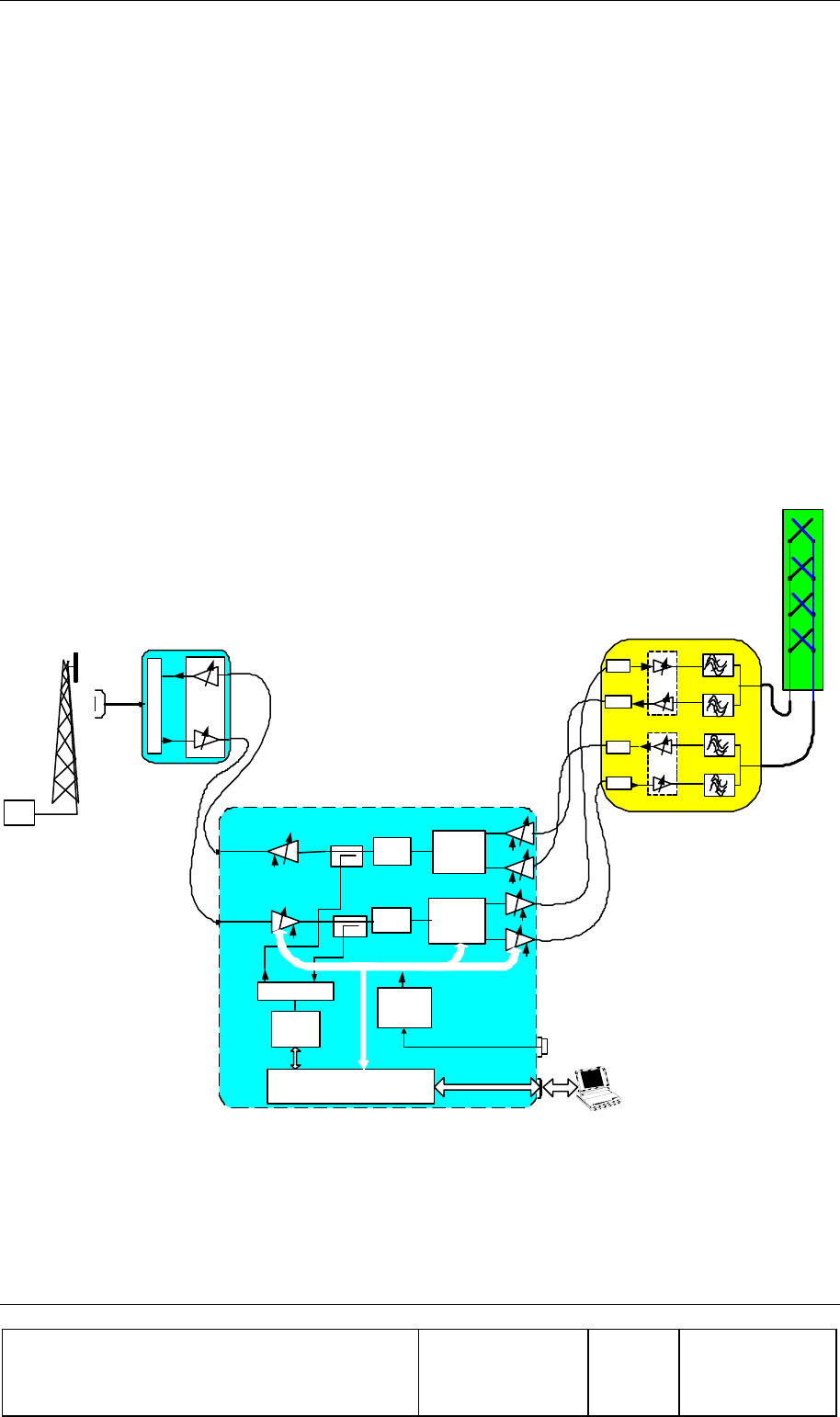
The following Figure shows the system block diagram which defines the terminology used
hereinafter.
Lap
Top
-60dB
Duplexer
Wireless
CDMA
Modem
DL SAW
Channel
Filter
Control Card
Power
Supply
220VAC
to 24VDC
ABT Rx
220VAC
24VDC
24VDC
RAC
RS-485
RS-232
24VDC
-60dB
UL SAW
Channel
Filter
ABT Tx
24VDC
ABT Rx
ABT Rx
24VDC
UL
Diversity
Unit
ABT Tx
24VDC
ABT Tx
24VDC
DL
Diversity
Unit
UL Main
UL
Diversity
DL Main
DL Diversity
BEAMER
L.A
L.A
L.A
L.A
BEAMER
X Pol
Antenna
PCS FlexBeamer
Donor
Antenna
BAU
BTS
Tx/Rx
Duplexer
Figure 9: PCS RF Repeater Block Diagram

FLEXBEAMER® RF Repeater System Set-Up and Tuning
Confidential, Proprietary Information
Title: PCS FlexBeamer® RF Repeater
System A &O Manual
Doc. No.: 913002500 Rev.: 00 Page: 45 of 84
3.2.1. Donor Antenna Setting
1. Install the Repeater Donor Antenna and direct it optimally towards the Donor Sector.
2. Connect a Pilot Scanner to the Donor Antenna port for verifying that the requested sector is
relayed.
3. Record the maximum pilot signal level at the Donor Antenna terminal:
• Pilot PN Sequence Offset: _________
• Pilot power Pp _________[dBm]
• Pilot quality Ec/Io: ____________[db]
3.2.2. Repeater Down Link (DL) Gain Setting
The overall DL gain is settable in the rang of : 35dB to 95 dB by using the Remotely controlled
Attenuators of the BAU, FLEXBEAMER® and RAC. The following procedure will define the
optimum DL gain setting.
1. FLEXBEAMER® Gain Setting
Calculate the required Pilot Power according to the normal Site Planning Procedure to be
transmitted by the Repeater Array, according to the required coverage area, using the Network
planning tools. Since the maximum FLEXBEAMER® total power is 8 (2x4) watts, the maximum
allocated Pilot Power is 0.8 Watts (+29dBm) (20% of total power).
The FLEXBEAMER® Gain is settable over a 15.5 dB range , in 0.5 dB steps.
Denoting the required Pilot Power PP (= 2x0.8Watt) , the FLEXBEAMER® amplifier attenuator
should be set to:
FLEXBEAMER® Attenuation setting = 10 log 10 (PT max/10) =10 log 10 (PP/a.10)[dB]
……(1)
When PT max=Watt
Example: Assume your Network Planning tool requires the Max. Pilot Power
from the Distribution Array to be 1W. The FLEXBEAMER® attenuation should
be set according to (1) to the following Value:
FLEXBEAMER® Att. Value= 10 log10 (1/2.0)= -3.01 db ( rounded to 3db)

FLEXBEAMER® RF Repeater System Set-Up and Tuning
Confidential, Proprietary Information
Title: PCS FlexBeamer® RF Repeater
System A &O Manual
Doc. No.: 913002500 Rev.: 00 Page: 46 of 84
2. DL Low Power Chain Gain Setting
2.1 Calculating the Gain of the DL FLEXBEAMER® units: The Max. gain of
the DL amplifiers in the RAC is 95 db. This gain amplification is composed of 4 successive
amplifiers- The BAU LNA, DL Rx ABT, the DL Tx ABT and the FLEXBEAMER® Beamer
each contributes approximately 15dB of the total FLEXBEAMER® adjustable DL gain.
The total gain of the DL Amplifiers of the RAC should be set to the value which will bring the Pilot
Ec received at the Donor Antenna to the required value at the FLEXBEAMER® input. Thus the
DL Gain of the Repeater System should be set to the following value:
Total Gain of DL in Repeater = +Pp–P’p [dB]……………..(2)
Where Pp denotes the DL signal input to the Donor Antenna ………….(3.1.1).
Example:
If the Pp measured at the Donor antenna is –60dbm, the total required gain of
the DL amplifiers of the RAC is +27-(-60)=+87db ………..(2.1)
2.2 Dividing the Gain between the FLEXBEAMER® Repeater stages: After
calculating the total DL gain of the FLEXBEAMER® Repeater per equation (2), the gain should
be divided between the 4 stages of the DL FLEXBEAMER® Repeater chain. following are the
recommendations for doing that:
a. Start the process by setting all the DCA attenuation in the BAU and RAC to
15.5dB.
b. Start reducing the Attenuation from max. at the BAU first(which is the first
amplifier in the chain.
c. The second DCA to reduce the attenuation is the Rx ABT(second amplifier in the
chain).
d. The third DCA to be reduced it’s attenuation will be the Tx ABT.
Example:
According to the process in example (2.1) , one needs to have +71db gain out
of the +95 db available. Following the steps a-c, the DL Tx ABT attenuator is
set to 14dB attenuation, and the Rx ABT set to –10dB.
Note
The DL Main and Diversity EIRP’s should be equal in order to achieve the
maximum diversity gain.
Check by reducing the DL Diversity TX gain by –15.5 dB and check the
power (actual or through the BSM indication) of the Main channel.
Repeat the same procedure for the Diversity channel by reducing the Main TX
channel.

FLEXBEAMER® RF Repeater System Set-Up and Tuning
Confidential, Proprietary Information
Title: PCS FlexBeamer® RF Repeater
System A &O Manual
Doc. No.: 913002500 Rev.: 00 Page: 47 of 84
3.2.3. Repeater Up-Link (UL) Gain Setting
The overall UL gain is settable in the range of : 35dB to 95dB.
1. Set the FLEXBEAMER® LNA’s gain to +30 db ( DCA set to 0db attenuation).
2. Set the repeater UL RAC and BAU amplifiers (UL Rx ABT, UL Tx ABT, BAU P.A) gain to
minimum. This corresponds to a total UL gain of 50dB, including the FLEXBEAMER® amplifiers
3. Drive with a MS to the far – out border of the Repeater coverage area, and observe the
Mobile Tx Power (in test mode). Operate the repeater Remote Control SW to remotely control
the RAC UL amplifiers gain.
3.1 If the Mobile Tx Power is maximum (+23dBm), increase BAU UL PA Amplifier gain in
1dB steps until the Mobile Tx Power drops 2 dB bellow its maximum. If required , increase
the gain of the UL Rx ABT and than the gain of the UL Tx ABT.
3.2 If the Mobile Tx Power is less than 2db below its maximum (+23dBm), decrease the
FLEXBEAMER® Rx Gain in 1dB steps, Until the MS reaches the maximum of +21dbm
Mobile Tx Power.
*Note: This procedure guarantees a fade margin for UL of 2 db. In practice, the Operator should utilize
the required fade , according to the Site Planning rules. More margins are possible by further increasing
the UL repeater gain and observing the lower MS Tx Power. This should be tested in a drive tests
along the distribution side coverage border.
NOTE
The UL main and Diversity should be equalized: Measure power out of the BAU while attenuating the
main or diversity gain by –15.5 dB.
3.2.4. Repeater DL gain Fine Tuning
For optimum DL and UL balancing it is recommended to have additional fine tuning
procedure performed on the DL, after going through the previous processes.
1. Drive with a MS to the outskirt bounderies area of the Repeater coverage area ( the
same coverage border you have set for the UL) and observe the Mobile Ec/Io (in test
mode).
2. Operate the repeater Remote Control SW to control the FLEXBEAMER® System
DL amplifiers Chain.
3. If the Mobile Ec/Io is low or marginal ( Ec/Io = -14db ) increase RAC DL Amplifiers
( DL Rx ABT, DL Tx ABT) gain in 1dB steps until the Mobile Ec/Io is set to the
Operator’s network design desirable values.

FLEXBEAMER® RF Repeater System Set-Up and Tuning
Confidential, Proprietary Information
Title: PCS FlexBeamer® RF Repeater
System A &O Manual
Doc. No.: 913002500 Rev.: 00 Page: 48 of 84
4. If the Mobile Ec/Io is high at the Coverage border, decrease the RAC DL amplifiers
( DL Rx ABT, DL Tx ABT) Gain in 1dB steps, Until the MS Ec/Io reaches the
Operator’s Network Design desirable values.
This Concludes the Repeater Optimal gain Setting..
FLEXBEAMER® RF Repeater System Set-Up and Tuning
Confidential, Proprietary Information
Title: PCS FlexBeamer® RF Repeater
System A &O Manual
Doc. No.: 913002500 Rev.: 00 Page: 49 of 84
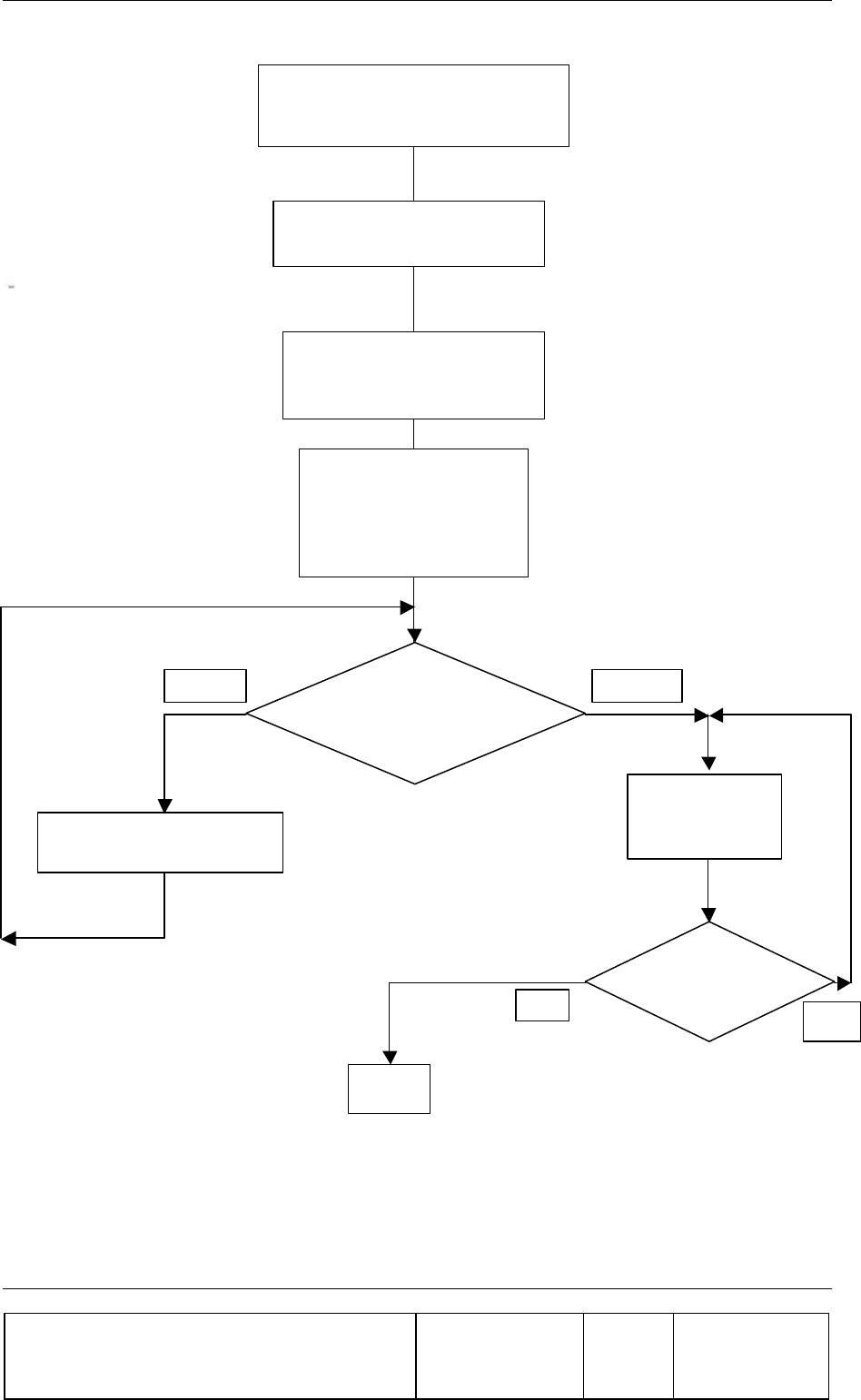
Set Donor Antenna and Record
Pilot Power
Set RAC, BAU DL gain , and
Repeater Amplifier DL Gain
Set FlexBeamer UL gain to
30dB (0dB attenuation). set
UL amplifier gain to
Drive with a MS (in test
mode) to Repeater Site
boundary, and observe
Mobile Tx Power ** in a
call
Mobile Tx Power
at maximum?
Decrease RAC UL gain in
1 dB step
Increase UL
amplifier gain in
1dB step
-
2db max MS
Tx Power ?**
END
No
Yes
Yes
No
Figure 10: PCS RF Repeater Block Diagram
** Note: This Value is determined by each Operator using the required fade margin and
performed at several areas along the distribution side border in drive tests.

BSM (BEAMER® SYSTEM MANAGER) Sofware PROGRAM
Confidential, Proprietary Information
Title: PCS FlexBeamer® RF Repeater
System A &O Manual
Doc. No.: 913002500 Rev.: 00 Page: 50 of 84
4. BSM (BEAMER® SYSTEM MANAGER)
SOFWARE PROGRAM
The BSM program enables monitoring and control of the BEAMER® units of both the
FLEXBEAMER® and the BEAMER® unit of the RAC, from a local or remote PC based host
computer.
Its main functions are:
? Control of system capacity and configuration
? Control of each BEAMER®
? Setting the Active Bias-T amplifiers gains for Up and Down links.
? Status report for each Array
? Status report for each BEAMER®
? Monitoring & Control of the RAC functions and Active Bias-Ts (ABTs)
? Set RF channel in channelized repeater.
4.1. Requirements for Operation
4.1.1. PC Hardware and operating System
• A PentiumTM based PC and a serial port on the PC
• Window 95/98/NT operating system
4.2. User Interface Description
4.2.1. Main Menu - BEAMER® (Active Radiating Module) System Manager
The BEAMER® System Manager enables:
Display of systems status report such as:
? Status of each Array and Sub-array
? Real time date and clock
? Authorized level for changes
Access to the following operating menus and functions:
? System
? Password

BSM (BEAMER® SYSTEM MANAGER) Sofware PROGRAM
Confidential, Proprietary Information
Title: PCS FlexBeamer® RF Repeater
System A &O Manual
Doc. No.: 913002500 Rev.: 00 Page: 51 of 84
? BEAMER® monitoring and control
4.2.2. System Menu List
The SYSTEM menu list provides the functions to set system parameters. It consists of four menus:
Definition, Configuration, Array Control and Com port
4.2.2.1. System definition Menu
The Capacity menu enables definition of the number of arrays in the system and type of array.
4.2.2.2. Configuration Menu
The Configuration menu enables:
? Registration of new BEAMER® units in the system..
? Display the ID number of each BEAMER® unit in the system.
? Definition of the conditions for failure messages.
? Definition of the shutdown conditions for the Power Amplifiers.
? Definition of status limits for failure messages (displayed by the RAC , the user
interface and sent to the BEAMER® concentrating unit).
4.2.2.3. Com Menu
The Com menu enables selection of an available serial port
4.2.2.4. Array Control
The Array Control menu enables setting the gain for each Active Bias T (ABT) in the system.
4.2.2.5. Password Menu List
The Password menu list enables entering the password to apply changes in system configuration.
Four levels of security password are available:
1. "Guest" level can only observe indications.
2. "Operator" level can apply changes to System configuration setting menu and BEAMER®
setting menu in addition to "Guest" abilities.
3. "Supervisor" level can apply changes to the system settings, such as Capacity/Failure conditions
and Limit/Shutdown conditions, in addition to the "Operator" abilities.
4. "Administrator" can change the passwords in addition to "Supervisor" abilities.

BSM (BEAMER® SYSTEM MANAGER) Sofware PROGRAM
Confidential, Proprietary Information
Title: PCS FlexBeamer® RF Repeater
System A &O Manual
Doc. No.: 913002500 Rev.: 00 Page: 52 of 84
4.3. Status Reports
4.3.1. Report by Monitoring
Either a PC or remote- connected PC (Via Modem or Wireless Modem) can be used for Monitoring
and Control of the BEAMER® RF Repeater System. The communication standard between the RAC
and the local or remote PC is by a standard RS-232/RS485 bus at a baud rate of 9.6 Kbps.
4.3.2. BEAMER® RF Repeater System Control
Either a PC or remote- connected PC can be used for Control each individual BEAMER® and each
of the BEAMER® RF Repeater ABT amplifiers. Local or remote PC can obtain control functions but
not both simultaneously.
4.4. BSM S/W
The BSM Software enables system configuration and monitoring functionality of each unit in the
system.
The Operation of the software will be described in the following paragraphs.
4.4.1. S/W Installation
The BSM software installation is from a diskette which is supplied with the product by Celletra .
• Put disk no.1 in the floppy drive and run "Setup".
• Follow the instructions on the screen until completion of installation.
4.4.2. S/W Operation
From the "Program files" in the Windows operating system select the BEAMER® icon and double
click to operate the BSM software.
Follow the next steps in order to establish a correct system installation.
Note: The ICU ( Interface and Control Unit) is the Control Board located within the RAC module of
the BEAMER® RF Repeater. When ever the ICU is referenced in the following BSM slide show the
interpretation should be the RAC Module Control Board.
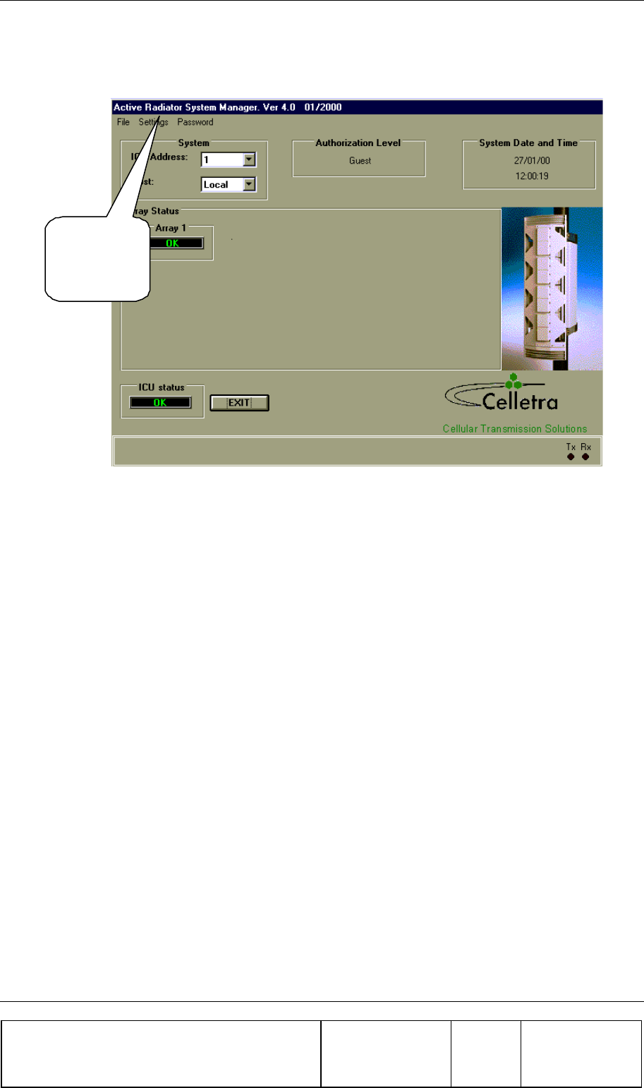
BSM (BEAMER® SYSTEM MANAGER) Sofware PROGRAM
Confidential, Proprietary Information
Title: PCS FlexBeamer® RF Repeater
System A &O Manual
Doc. No.: 913002500 Rev.: 00 Page: 53 of 84
4.5. BSM Main Screen
From the
Setting
menu
select the
Comm port.
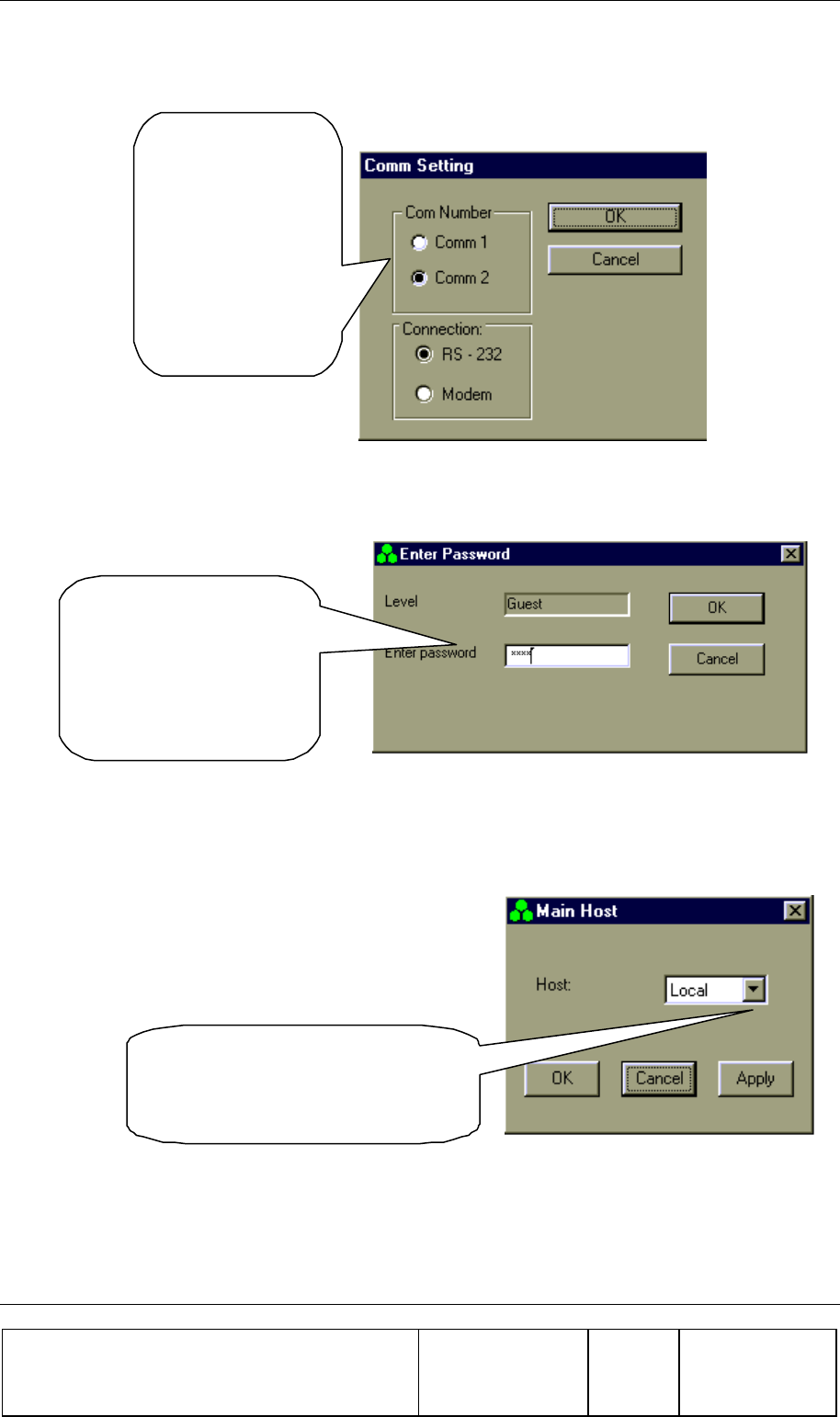
BSM (BEAMER® SYSTEM MANAGER) Sofware PROGRAM
Confidential, Proprietary Information
Title: PCS FlexBeamer® RF Repeater
System A &O Manual
Doc. No.: 913002500 Rev.: 00 Page: 54 of 84
4.6. Comm Port Selection
Connect RS-232
or RS-485 cable
to the ICU.
Run the cable to a
Comm port on
your PC.
4.7. Password Entering
In order to create or
modify a
configuration, you
will need
"Administrator”
password level.
4.8. Host Selection
From the Setting menu select
Main Host and then select either
Local or Remote Host.
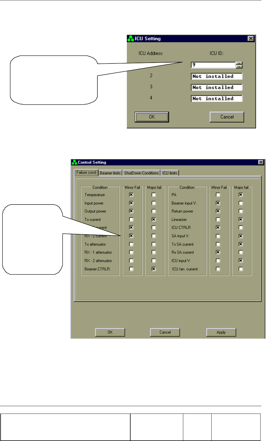
BSM (BEAMER® SYSTEM MANAGER) Sofware PROGRAM
Confidential, Proprietary Information
Title: PCS FlexBeamer® RF Repeater
System A &O Manual
Doc. No.: 913002500 Rev.: 00 Page: 55 of 84
4.9. Installation of RAC in System
Operate ICU 24VDC Power
Supply .
Read ICU ID and ICU
addresses.
4.10. Failure Conditions Selection
Select Major or
Minor Fail
according to
operator
application
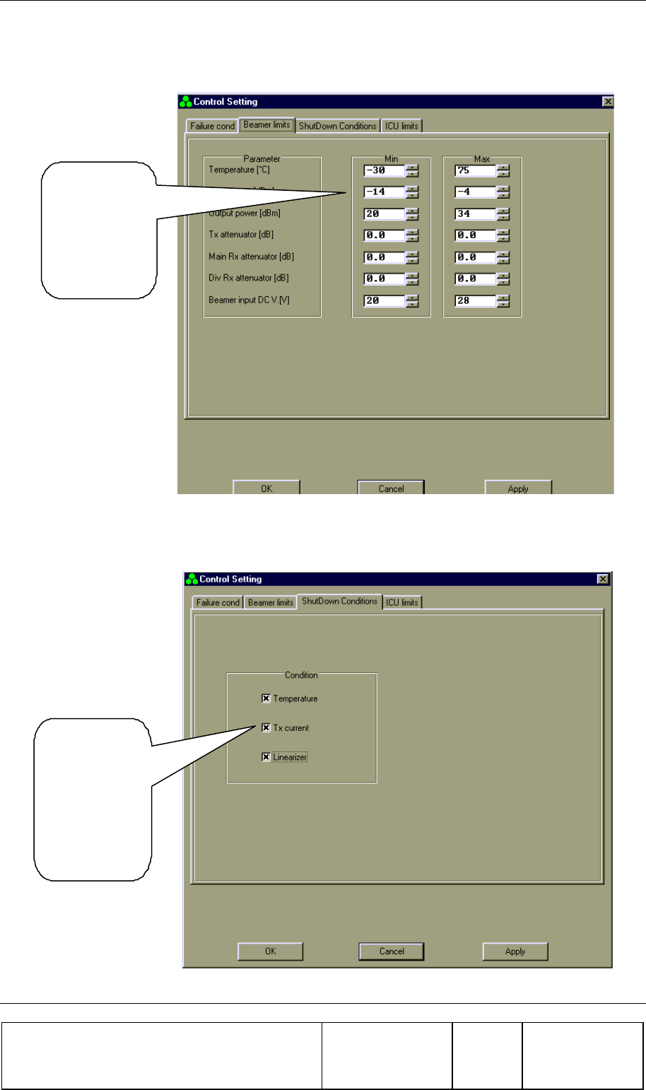
BSM (BEAMER® SYSTEM MANAGER) Sofware PROGRAM
Confidential, Proprietary Information
Title: PCS FlexBeamer® RF Repeater
System A &O Manual
Doc. No.: 913002500 Rev.: 00 Page: 56 of 84
4.11. BEAMER® Limits Definition
Select limits
according to
operator
application
4.12. Shut Down Conditions Enable/Disable
Enable or
disable Shut
Down
conditions
according to
operator
aplication.
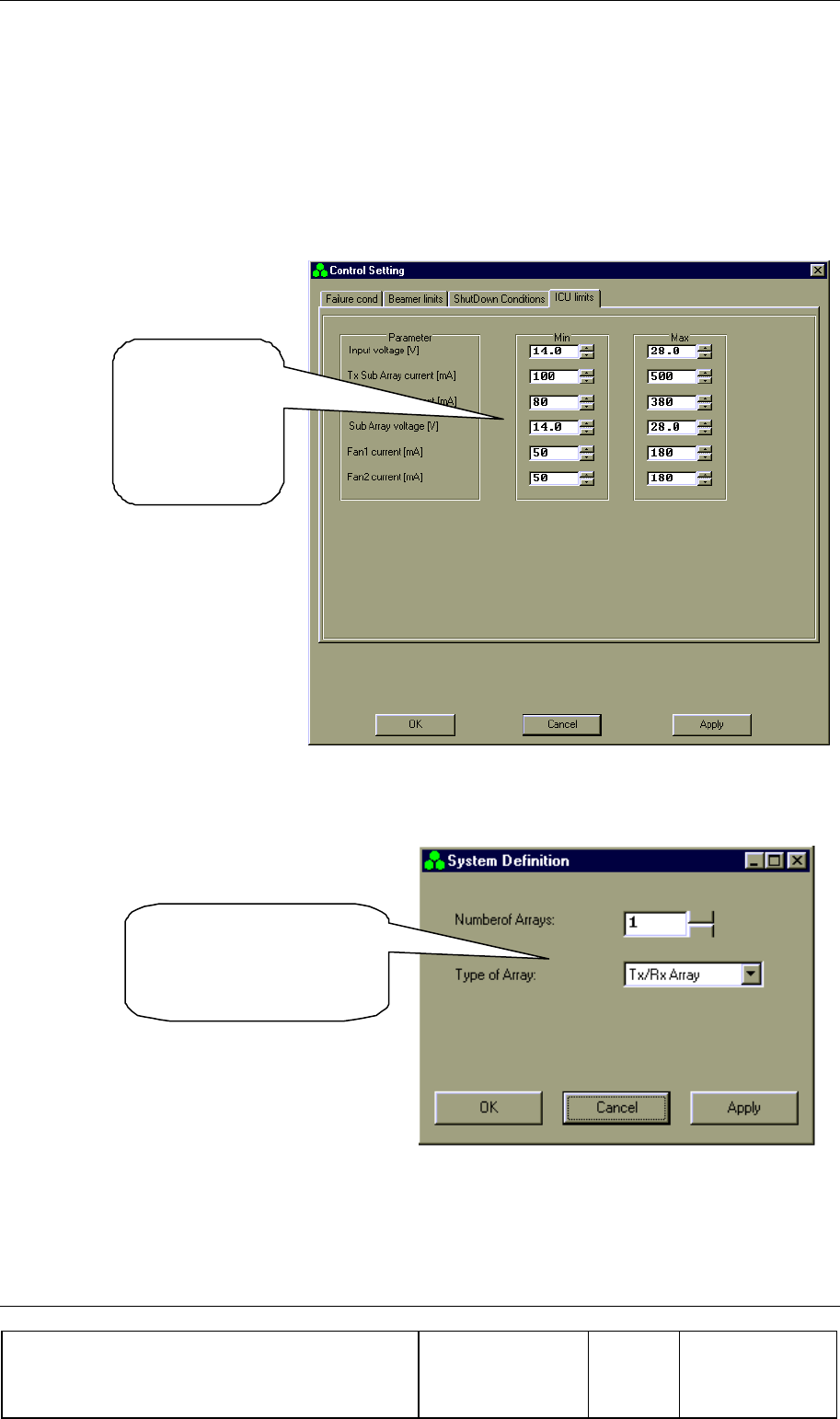
BSM (BEAMER® SYSTEM MANAGER) Sofware PROGRAM
Confidential, Proprietary Information
Title: PCS FlexBeamer® RF Repeater
System A &O Manual
Doc. No.: 913002500 Rev.: 00 Page: 57 of 84
The “Shut Down Conditions” should be saved only after BEAMER® installation paragraph
4.18
4.13. RAC Limits Definition
Select
ICU limits
according to
operator
application
4.14. System Definition
Define the Number of
Arrays and the Type of
Arrays in your system.
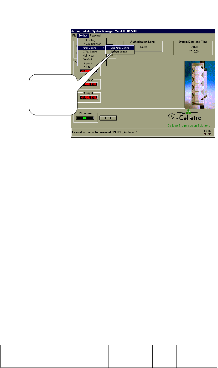
BSM (BEAMER® SYSTEM MANAGER) Sofware PROGRAM
Confidential, Proprietary Information
Title: PCS FlexBeamer® RF Repeater
System A &O Manual
Doc. No.: 913002500 Rev.: 00 Page: 58 of 84
4.15. Sub-Array and BEAMER® Setting
From the Setting
menu select Array
Setting and
SubArray Setting.
(See instructions on
next page)
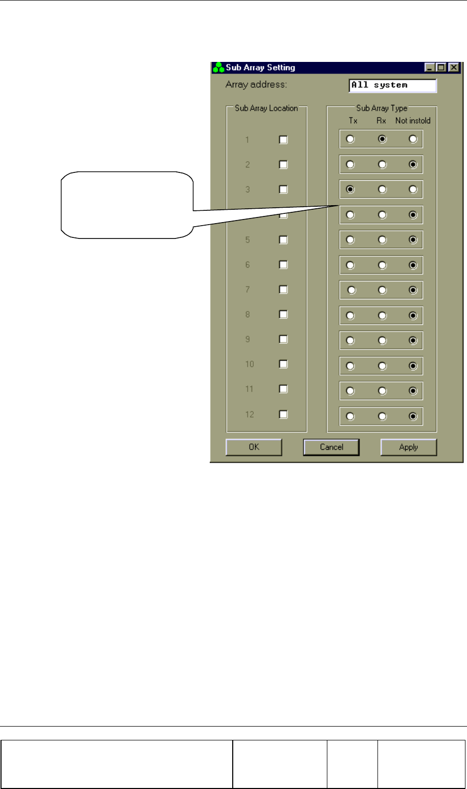
BSM (BEAMER® SYSTEM MANAGER) Sofware PROGRAM
Confidential, Proprietary Information
Title: PCS FlexBeamer® RF Repeater
System A &O Manual
Doc. No.: 913002500 Rev.: 00 Page: 59 of 84
4.16. Sub Array Setting
Define Bias-Ts
according to system
definition and array
location
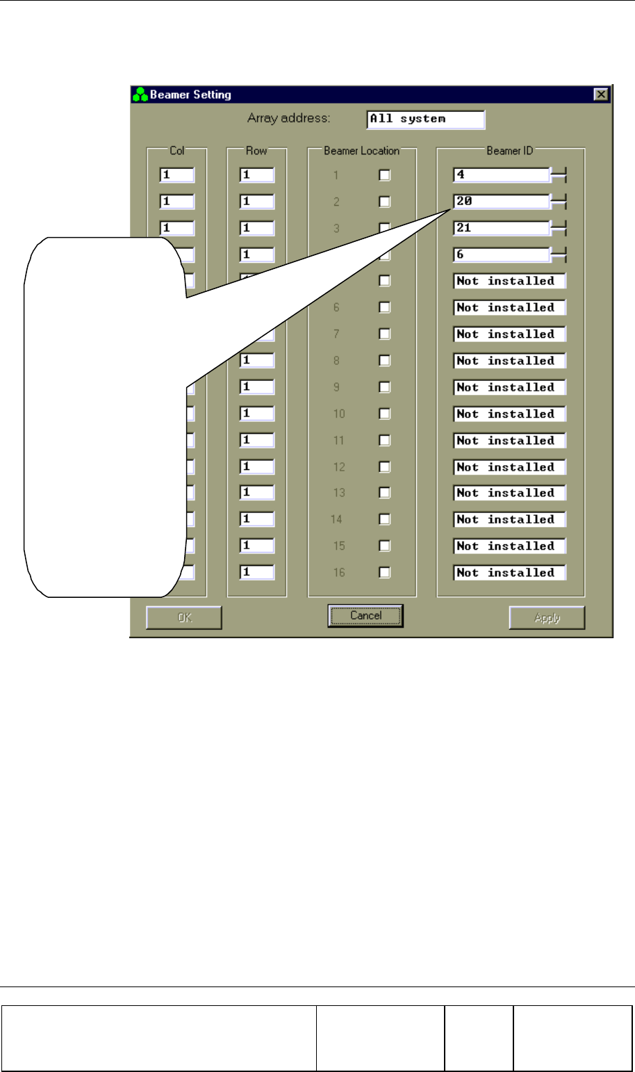
BSM (BEAMER® SYSTEM MANAGER) Sofware PROGRAM
Confidential, Proprietary Information
Title: PCS FlexBeamer® RF Repeater
System A &O Manual
Doc. No.: 913002500 Rev.: 00 Page: 60 of 84
4.17. BEAMER® Installation
From BEAMER
Setting select
BEAMER.
The S/W starts
looking for installed
BEAMERs.
Wait until Apply
button becomes
available.
Add missing
BEAMERs or make
changes according to
existing installation
by adding BEAMER
ID numbers.
Confirm by clicking
Apply button.
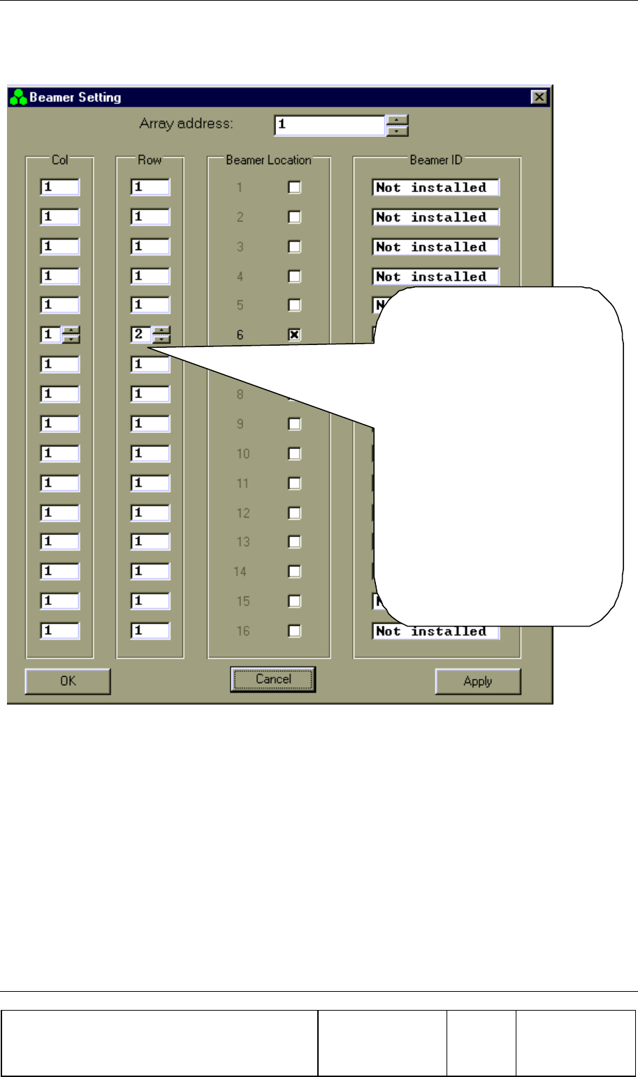
BSM (BEAMER® SYSTEM MANAGER) Sofware PROGRAM
Confidential, Proprietary Information
Title: PCS FlexBeamer® RF Repeater
System A &O Manual
Doc. No.: 913002500 Rev.: 00 Page: 61 of 84
4.18. Column and Row Definition
In the Array address combo
box, select the Array number.
Check the Beamer Location.
Enter the Col and Row for the
Beamer.
Repeat for each Beamer in the
Array.
Click Apply when you have
completed an Array of
BEAMERs.
Repeat this procedure for all
the Arrays.
Click OK.
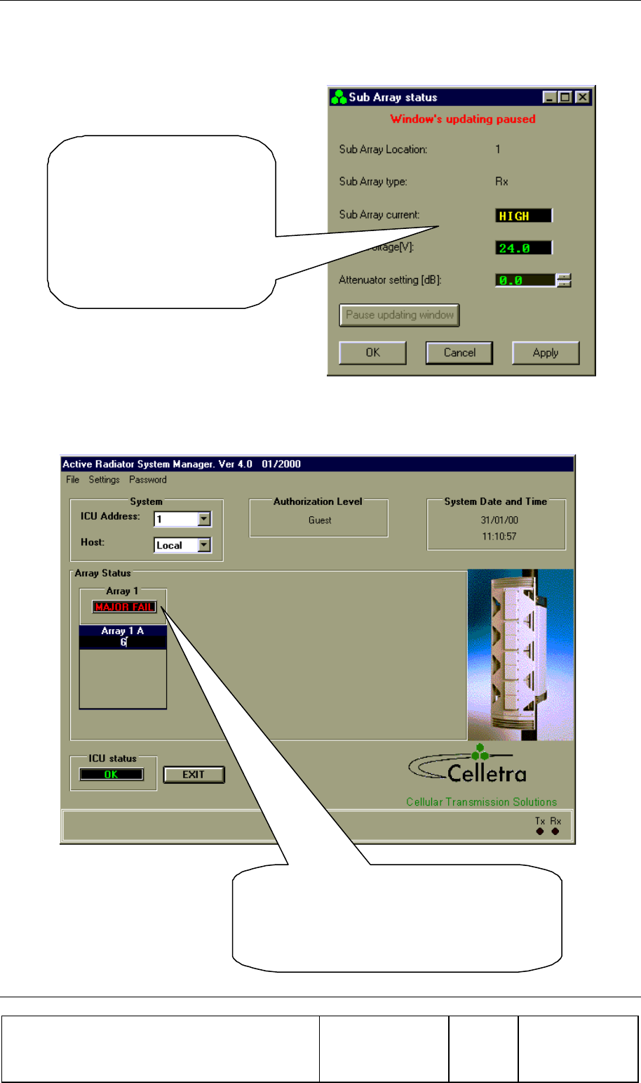
BSM (BEAMER® SYSTEM MANAGER) Sofware PROGRAM
Confidential, Proprietary Information
Title: PCS FlexBeamer® RF Repeater
System A &O Manual
Doc. No.: 913002500 Rev.: 00 Page: 62 of 84
4.19. Sub-Array Status and Attenuator Setting
Select from Array Status
window an Array and select
Sub-Array option.
Click Pause Updating Window
and adjust the attenuator value
between 0 and 15.5 dB.
Click Apply in order to save
your selection.
4.20. Control & BEAMER® Setting
Point cursor at an Array window.
Click to view all BEAMER addresses in
selected Array.
Double click to see BEAMER Control screen.
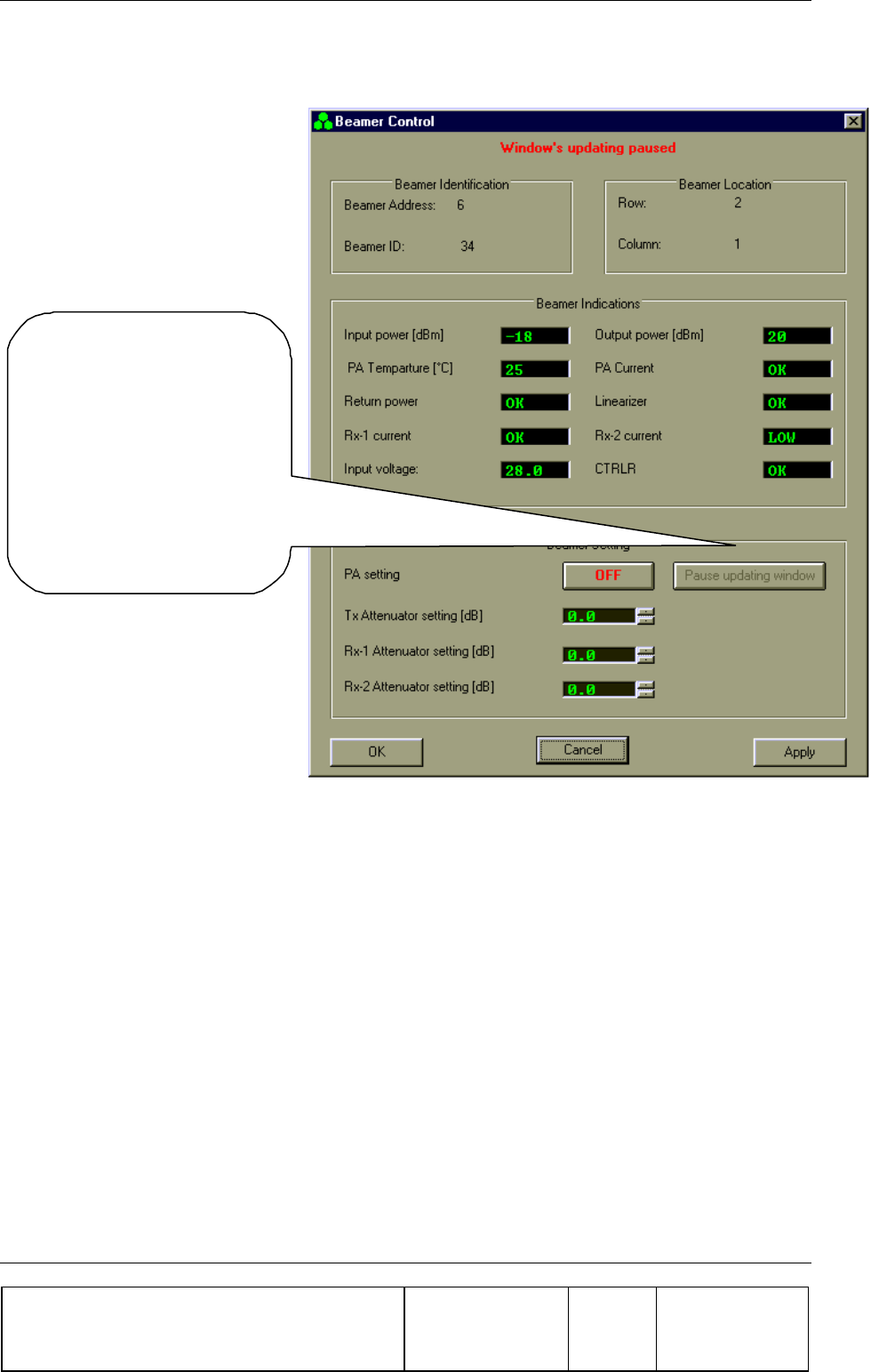
BSM (BEAMER® SYSTEM MANAGER) Sofware PROGRAM
Confidential, Proprietary Information
Title: PCS FlexBeamer® RF Repeater
System A &O Manual
Doc. No.: 913002500 Rev.: 00 Page: 63 of 84
4.21. BEAMER® Control
Click
Pause Updating
Window and select
attenuator value for Tx and
Rx according to your
system definition.
Click Apply to save your
selection.
Click OK to return to Main
screen.
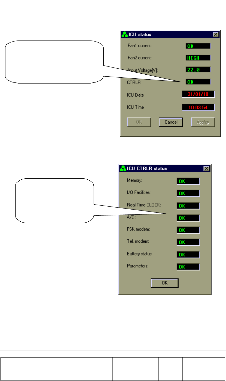
BSM (BEAMER® SYSTEM MANAGER) Sofware PROGRAM
Confidential, Proprietary Information
Title: PCS FlexBeamer® RF Repeater
System A &O Manual
Doc. No.: 913002500 Rev.: 00 Page: 64 of 84
4.22. RAC Status
Click on
ICU
window to see ICU
status.
In case of a failure, double click on
it to display details
4.23. RAC CTRLR Status
Double click on the
CTRLR window to view
this box, which shows the
CTRLR parameters in
detail.
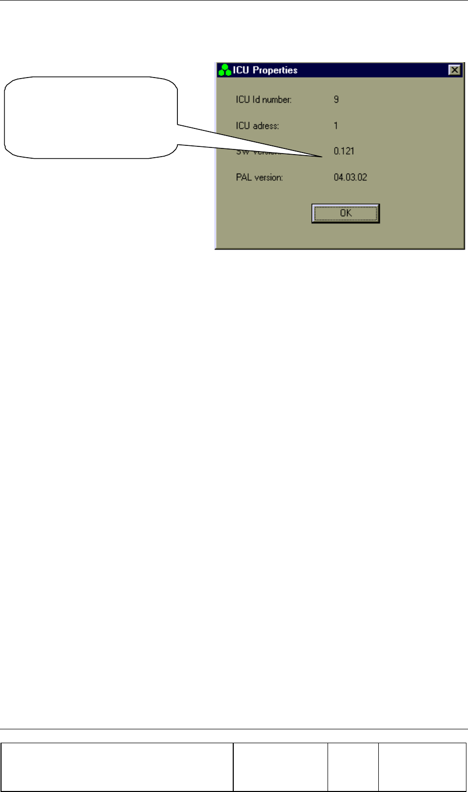
BSM (BEAMER® SYSTEM MANAGER) Sofware PROGRAM
Confidential, Proprietary Information
Title: PCS FlexBeamer® RF Repeater
System A &O Manual
Doc. No.: 913002500 Rev.: 00 Page: 65 of 84
4.24. RAC Properties
From Setting you can select
ICU Properties to view the
SW versions of the ICU
CTRLR card

BSM (BEAMER® SYSTEM MANAGER) Sofware PROGRAM
Confidential, Proprietary Information
Title: PCS FlexBeamer® RF Repeater
System A &O Manual
Doc. No.: 913002500 Rev.: 00 Page: 66 of 84

Confidential, Proprietary Information
Title: BEAMER Array System-
Assembly and Operation Manual
Doc. No.: 913002500 Rev.: 00 Page: 67 of 84
5. NEW SOFTWARE DOWNLOAD GUIDE
5.1. Introduction
This chapter is a guide to loading program files to the RAC and BEAMER® via their Monitoring and
Control communication channels. This enables program upgrades in the field without dismantling the
equipment for that purpose.
The program loading is done from a PC when using the CELLETRA SOFTWARE DOWNLOADING
SYSTEM program, which is supplied by CELLETRA.
This chapter describes the loading process to the RAC and the BEAMER® using the CELLETRA
SOFTWARE DOWNLOADING SYSTEM.
5.2. Overview
5.2.1. Downloading Software to the RAC
In the software download process a new application program file is loaded to the RAC via the serial
communication channel or Wireless Modem and saved to the FLASH memory.
5.2.1.1. RAC Memory Configuration
The RAC controller includes two types of memories a FLASH memory and a RAM. The FLASH
memory includes the configuration parameters of the RAC (such as ID number, number of arrays,
failure conditions etc.) and the application program, which enables all the features of the RAC and
which is upgradeable.
The RAM is used for logging events into the log file during regular operation of the RAC, and for
receiving the new application program for the RAC during the download process. A third memory is

Confidential, Proprietary Information
Title: BEAMER Array System-
Assembly and Operation Manual
Doc. No.: 913002500 Rev.: 00 Page: 68 of 84
located in the CPU component and includes the basic I/O program of the controller. This program
enables operation of the basic functions of the controller (such as serial communication and application
program loading) and cannot be modified. The memory size allocated for the application is 64 Kbytes.
Programming a new application program into the FLASH memory does not affect the RAC
configuration parameters.
5.2.1.2. RAC Download Operation Mode
Loading a program file to the RAC is enabled while the RAC operates in Download mode. The
operation mode of the RAC is changed by a command through the serial communication channel.
When the RAC operates in Download mode, no operational function is performed. (That means that it
does not provide monitoring and control of the BEAMER® s). The baud rate of the serial port
increases to 56K baud. That enables faster transmission of data packets to the RAC during the
download process. The RAC returns to operational mode (Auto) at the end of the loading process or if
there was no data transmission from the PC within a predefined time period .
5.2.1.3. File Transmission From PC to RAC
5.2.1.3.1. File Transmission
The program file is a HEX type file and the data is ASCII format. While loading the file to the RAC
the PC sends the file content line by line. The RAC reports TO the PC about reception quality. If
errors were detected the transmission will be stopped and an error message will be displayed. The PC
then restarts the transmission. The program is contained in files of 64 Kbytes. That is, if the program
size is greater than 64 Kbytes it will be packed in two files that are distinguished by their names.
5.2.1.3.2. File Name Format
The file name has the following format: IDUxxTVVV.Hyy
IDU RAC application header
Xx Not relevant for loader
T Application type (0,2,3=Celletra ICU/1=Micro ICU)
VVV Application version
Hyyy HEX: The program is packed in one HEX file
H00 and H01: The program is packed in two HEX files
Example: IDUck0102.h01
IDUck: Software application
0: Celletra version
102: Software version number
h01: High package of the hex file

Confidential, Proprietary Information
Title: BEAMER Array System-
Assembly and Operation Manual
Doc. No.: 913002500 Rev.: 00 Page: 69 of 84
5.2.2. Downloading Software to the BEAMER®
The Software download process enables loading of a new application program file for the BEAMER®
host processor and the DSP via the serial communication channel and saving it to the FLASH memory
in the BEAMER® .
5.2.2.1. BEAMER® Memory Configuration
The BEAMER® includes two processors a DSP and a HOST. The HOST processor is a general
purpose processor that is used for reporting BEAMER® status to the RAC via a FSK channel and for
initialization of the DSP.
The BEAMER® controller includes a FLASH memory that contains:
1. The configuration parameters of the BEAMER® (such as ID number, calibration tables etc.).
These parameters are not affected during the loading process.
2. The application program that enables all the features of the BEAMER® that can be replaced
by a new version.
3. The program and data files of the DSP that can be replaced by a new version.
The FLASH size contains two files of each program (two of HOST application, two program files for
the DSP, and two data files for the DSP). The required program files for operation are selected by the
user. The memory is arranged by pages (each page includes 128 bytes).
5.2.2.2. File transmission from PC to the BEAMER®
5.2.2.2.1. File Transmission
The new file is transmitted page by page from the PC to the RAC and from the RAC to the
BEAMER® . All files to be loaded are text files. The files contain a Header block, which is the
properties block, and the software to be loaded. When the load process is enabled, the baud rate of the
serial port (from PC to the RAC) increases up to 56K Baud. That enables faster transmission of data
packets to the RAC during the download process. The RAC reports the PC about reception quality
and if errors occurred, the transmission will be stopped and an error message will be displayed.
The RAC sends the data packets received from the PC to the BEAMER® and the BEAMER®
reports the RAC about reception quality. If errors were detected the transmission will be stopped and
an error message will be displayed
5.2.2.2.2. File Name Format for HOST
Files will be identified by the following suffix: name.hst

Confidential, Proprietary Information
Title: BEAMER Array System-
Assembly and Operation Manual
Doc. No.: 913002500 Rev.: 00 Page: 70 of 84
5.2.2.3. File Name Format for DSP
Files will be identified by the following suffixes:
• DSP Program file: name.dpm
• DSP Data file: name.ddm
5.3. User Interface for SW Download
5.3.1. Functions
The Software download program enables download program files to the RAC and the BEAMER®
module from a local PC-based host computer.
Its main functions are:
• Selection of the target for downloading (BEAMER® or RAC)
• Selection of files to be loaded
• Transmission of files from the PC to the selected target (BEAMER® or RAC).
• Monitoring of transmission process
5.3.2. Requirements for Operation
5.3.2.1. Hardware
• PentiumTM-based PC
• Free serial port from the PC
• At least 4 Mb free RAM
5.3.2.2. Software
Window 95/98/NT operating system
5.3.3. User Interface Installation
The software is installed from a diskette supplied by Celletra.
1. Put disk no.1 in the floppy drive and run "Setup".
2. Follow the instructions on the screen until completion of installation.
The program will be installed in the "Program files" subdirectory of the “Windows” directory.
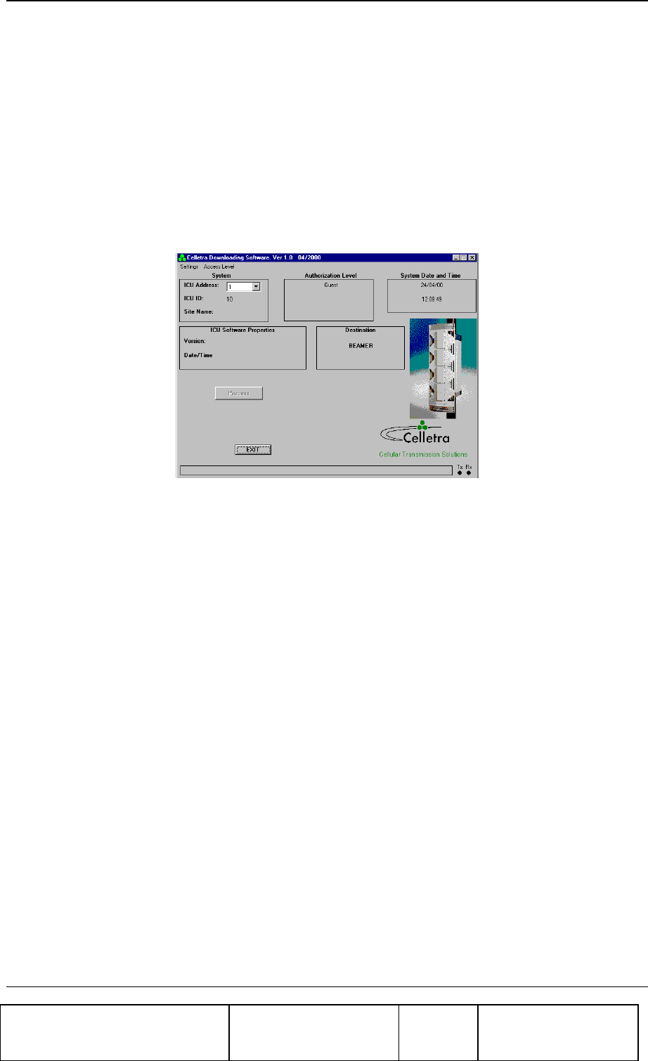
Confidential, Proprietary Information
Title: BEAMER Array System-
Assembly and Operation Manual
Doc. No.: 913002500 Rev.: 00 Page: 71 of 84
5.3.4. User Interface Operation
The program can be operated from the program menu in the start menu. Another option is to create a
shortcut for the program from the "Program files" subdirectory in the Windows directory and operate
the program by clicking the icon
5.4. User Interface Description
When operating the program the following window will be displayed:
5.4.1. System Field
The System field displays the address of the RAC and its ID number that is controlled by the operated
program. In case that the system includes few RACs the required RAC can be selected by its address
from the address bar.
When the program is operated it scans the addresses (1 to 4) and displays the address of the existing
RACs in the System filed . In case that no RAC was connected or the RAC was not configured the
address bar will remain blank.
5.4.2. Authorization Field
Authorization field displays the actual authorization level. Two levels of authorization are available:
1. "Guest" level can only observe indications.
2. "Administrator" which enables the application of the loading process and change the passwords
in addition to "Supervisor" abilities.
5.4.3. System Date and Time Field
System date and time function displays the PC’s actual date and time. That time will be registered as
one of the properties of the loaded file.

Confidential, Proprietary Information
Title: BEAMER Array System-
Assembly and Operation Manual
Doc. No.: 913002500 Rev.: 00 Page: 72 of 84
5.4.4. RAC SW Properties Field
RAC SW properties field is enabled when the loading process is enabled. It displays the properties of
the program file that exists in the RAC. The RAC property information includes the version number
and file loading date and time.
5.4.5. Destination Field
Destination field displays the destination for the file loading – BEAMER® or RAC.
5.4.6. Setting Menu
Setting menu includes the following functions:
• RAC Setting
• Software loading code
• Software remote loader
• Site name
• Destination
• ComPort
5.4.6.1. RAC Setting
If the connected RAC is not configured- (meaning that it does not have an address) - this function
enables defining and saving an address to the RAC. Click on ICU setting to display the following
window:
Setting RAC’s address is enabled by entering its ID number (which is known and is the RAC serial
number).
5.4.6.2. Software Loading Code
This function enables saving to the BEAMER® details about present loading. Software loading code is
an alphanumeric expression up to 20 characters.
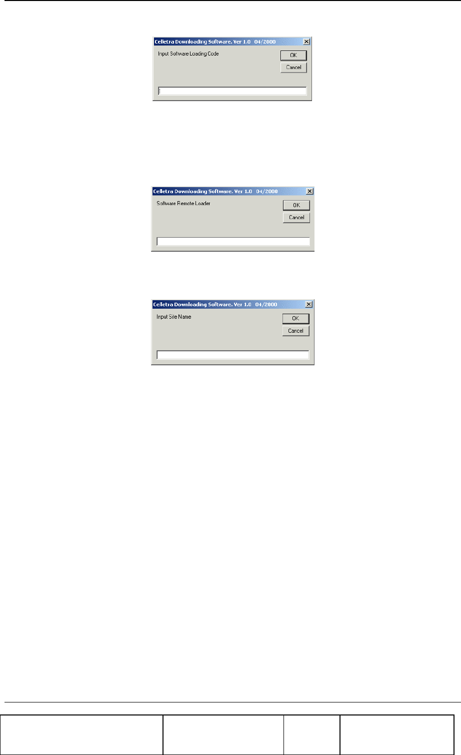
Confidential, Proprietary Information
Title: BEAMER Array System-
Assembly and Operation Manual
Doc. No.: 913002500 Rev.: 00 Page: 73 of 84
5.4.6.3. Software Remote Loader
This function enables saving of the program loader name into the BEAMER® . Software remote
loader is an alphanumeric expression up to 20 characters.
5.4.6.4. Site Name
This function enables saving to the BEAMER® the name of the site where a program was recently
loaded to that BEAMER® . Site name is an alphanumeric expression up to 20 characters.
5.4.6.5. Destination
This function enables selecting the required destination for the SW download: BEAMER® or RAC
5.4.6.6. ComPort
This function enables selecting the required communication path from the PC to the RAC. Selection of
ComPort function will display the Comm. setting window
Connecting the RAC is possible directly via RS232 interface for local connection or via telephone or
Wireless modem for remote connection. The remote connection is enabled in RAC versions that
include internal telephone or Wireless modem. The Comm. setting window enables selecting the
required path: RS-232 interface or modem. It displays all the available serial ports in the PC and
enables selecting a free port in the case where the RS-232 interface is selected.
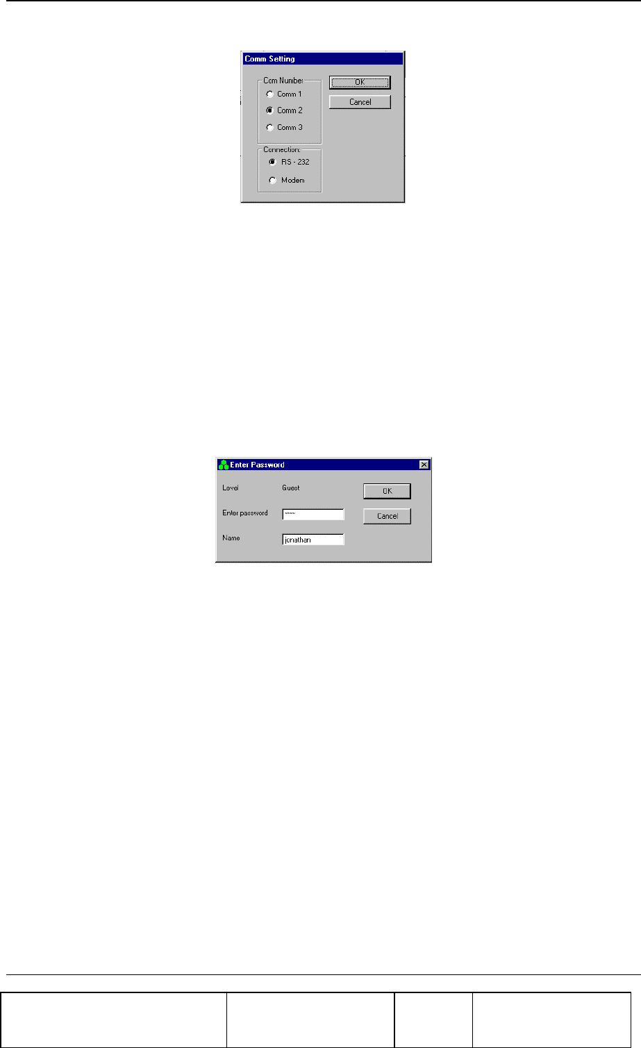
Confidential, Proprietary Information
Title: BEAMER Array System-
Assembly and Operation Manual
Doc. No.: 913002500 Rev.: 00 Page: 74 of 84
5.4.7. Password Menu
Password menu enables the inclusion of the following functions:
1. Enter password and user name
2. Low level
3. Change the Administrator password
5.4.7.1. Enter Password
Clicking on the Enter password function will display the following window:
The displayed window enables entering the required password, which enables the loading process.
5.4.7.2. Low Level
Clicking on Low Level sets the Guest level authorization.
5.4.7.3. Change Password
This function is enabled when the Administrator authorization is enabled and enables changing the
password for authorization.
5.5. Program Loading Procedure
5.5.1. Procedure for Loading Program to the RAC
To load a new version of application program file to the RAC controller, follow the following
instructions:
1. Connect the PC that includes the Celletra program loader program to the RAC via the serial
port or wire or Wireless Modem.
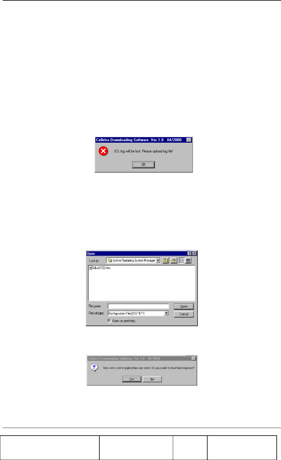
Confidential, Proprietary Information
Title: BEAMER Array System-
Assembly and Operation Manual
Doc. No.: 913002500 Rev.: 00 Page: 75 of 84
2. If you wish to keep the log file then save it, otherwise the log file will be erased during the new
file loading.
3. Operate Celletra program loader program and wait until the address of the RAC appears at the
RAC address bar. If the system includes few RACs, select the address of the required RAC
from the address bar.
4. From the Setting menu select Comport and select the required communication path to the RAC.
• If the PC is connected via the serial port of the PC then check the RS-232 and define the COMM
port in the PC that is used.
• If the PC is connected via the a telephone line by a modem, then check the MODEM and dial the
telephone number of the destination modem.
5. From the Setting menu, click on Destination and select RAC as the destination for loading. The
following warning message will appear to warn that the log file will be erased:
6. Exit to save the log file or Click O.K to continue. The properties of the existing file will be
displayed on RAC Software properties field.
7. Click on the Password menu then on Enter to enter the password that enables loading of a new
program. After you enter the correct password and your name the Start download command
key will be enabled.
8. Click the Start download command key to start the loading process. The following window will
be displayed:
9. Select the required file and click on the Open button. If the selected file is similar to the existing
(operational) file then following notice will be displayed:
10. If you wish to load the same file anyway then click Yes to continue, otherwise click No and
select other file.
11. During the loading process a status bar will be displayed:

Confidential, Proprietary Information
Title: BEAMER Array System-
Assembly and Operation Manual
Doc. No.: 913002500 Rev.: 00 Page: 76 of 84
12. Wait about 3 minutes until the process is completed. If you wish to stop loading the file then
click on the Cancel button.
13. After the file has been loaded into the RAM successfully the RAC will program the FLASH
memory. During the FLASH programming the following message will be displayed:
14. The new program version will operate at the end of this process and the RAC is operational
again.
15. If the loading process has been failed the following warning message will be displayed:
5.6. Procedure for Loading Program to the BEAMER®
To load a new file (application, DSP prog. file and DSP data file) to the BEAMER® controller
follow the following instructions:
1. Connect the PC that includes the Celletra PROGRAM LOADER program to the RAC via the
serial port.
2. If you wish to keep the log file then save it, otherwise the log file will be erased during the new
file loading.
3. Operate Celletra program loader program and wait until the address of the RAC appears at the
RAC address bar. If the system includes few RACs (ICUs), select the address of the required
RAC from the address bar.
4. From the Setting menu select Comport and select the required communication path to the RAC.
5. If the PC is connected via the serial port of the PC then check the RS-232 and define the
COMM port in t he PC that is used.
6. If the PC is connected via a telephone line by a modem then check the MODEM and dial the
telephone number of the destination modem.
7. From the Setting menu click on Destination and select BEAMER® as the destination for
loading.
8. Click on the Password menu then on Enter to enter the password that enables loading of a new
program. After you enter the correct password and your name the Start download command
key will be enabled.
9. Click the Start Download command key to start the loading process. Clicking the start download
button will display a window to enter the required BEAMER® ID number.
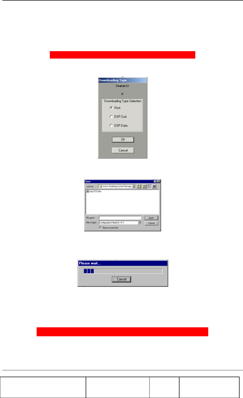
Confidential, Proprietary Information
Title: BEAMER Array System-
Assembly and Operation Manual
Doc. No.: 913002500 Rev.: 00 Page: 77 of 84
10. Enter the ID number of the required BEAMER® and click O.K to continue. In case that the
particular RAC ID number does not exist in the system the following warning message will be
displayed:
ERROR : BEAM ER NUMBR 51 IS NOT RESPONDING
Otherwise the following window will be displayed:
11. Check the required file type for loading and click OK to continue. The following window will
enable the selection of the particular file to be loaded:
12. Select the required file from the file list and click OPEN for loading
During the loading process a status bar will be displayed:
13. Wait until the process is completed. If you wish to stop loading the file then click on the Cancel
button.
14. After the file was loaded into the BEAMER® successfully the following message will be
displayed:
FILE LOAD WAS COMPLETED SUCCESSFULLY
15. The new program version will operate at the end of this process and the BEAMER® is
operational again.

Confidential, Proprietary Information
Title: BEAMER Array System-
Assembly and Operation Manual
Doc. No.: 913002500 Rev.: 00 Page: 78 of 84
6. SERVICING AND TROUBLE SHOOTING
THE BEAMER® RF REPEATER
6.1. servicing the RF Repeater
6.1.1. Back-up battery replacement
The back up battery is valid for about 10 years of normally use of the system.
Despite the above, it is recommended to replace back-up battery when opening the system for
maintenance activities.
6.2. Trouble Shooting
The following table detailed the common problems and recommended solutions.
Remark! In case of problems or dificulties, it is recommended to contact
“Celletra Technical Support”.
Error/Fault Check
System don’t start • Verify proper installation and power connections.
Monitoring and control problems • Check power to RS-232/485 adapter, verify comm port
definition on the BSM S/W.
Low/No Power • Operate BSM S/W and check the following parameters:
• Check DC power level in the BAU RAC and
FLEXBEAMER® using BSM S/W.
• Check damage to coax cables in case of bad results in previous
check.
• Verify system setup parameters.
• Check In/Out power parameters using BSM S/W.
• Replace faulty unit in case of “good input” and “bad output”
• In case of unit replacement start system setup from the
beginning.

Confidential, Proprietary Information
Title: BEAMER Array System-
Assembly and Operation Manual
Doc. No.: 913002500 Rev.: 00 Page: 79 of 84
System Alarms 1. Enter to the Beamer status screen and verify PA is “ON”
2. Look for alarms in one of the two defined arrays.
3. If PA is “OFF” try to turn it “ON”.
4. If you can not do so go to the Sub-array (ABT) “Attenuator
settings and increase the attenuation to avoid possible over drive
power to the Beamers.
5. If PA can be turned “ON” start system setup from the
beginning.
• If PA does not go “ON” replace the faulty unit.

Confidential, Proprietary Information
Title: BEAMER Array System-
Assembly and Operation Manual
Doc. No.: 913002500 Rev.: 00 Page: 80 of 84
6.2.1. Troubleshooting the system using ICU log file.
6.2.1.1. Getting ICU Log File
For getting the ICU Log File follow the instructions:
1. Select <FILE> option in the main menu.
2. Select <Get Log file> option. A small window, named “Save In” will be displayed. Set
the name of the Log file (or use the default name) and press <save>.
3. A ‘progress window’ will be displayed while reading the data from the ICU.
6.2.1.2. The Log file structure
The log file is a text file with a line of 26 fields
Field No. Field Name Description
1 Failure type
2 Date
3 Time
4 – 20 Beamer Status (relevant only for Beamer failure)
4 BEAMER address
5 Controller status 0 - OK; other - Fail
6 Temperature Indication checked within Beamer limits
7 Input Power Indication , Checked within Beamer limits
8 Output Power Indication Checked within Beamer limits
9 Tx Attenuator Indication Checked within Beamer limits
10 Main Rx Attenuator Indication, Checked within Beamer limits
11 Div Rx Attenuator Indication Checked within Beamer limits
12 Tx Current Indication Low - 0 Norm - 1 High - 2
13 Main Rx Current Indication Low - 0 Norm - 1 High - 2
14 Div Rx Current Indication Low - 0 Norm - 1 High - 2
15 Return Power Indication 0 - OK;1 - Fail

Confidential, Proprietary Information
Title: BEAMER Array System-
Assembly and Operation Manual
Doc. No.: 913002500 Rev.: 00 Page: 81 of 84
16 Tx Amplifier Status 0 - OFF;1 - ON
17 Correction Amplifier Status 0 - OFF;1 - ON
18 Linearizer Status 0 - OK;1 - Fail
19 Beamer Voltage Indication; Checked within Beamer limits
20 Communication Error Timeout or corrupted data
21-26 ICU Status (relevant only for ICU failure)
21 ICU Status
22 Fan1 Status
23 Fan2 Status
24 Voltage Status
25 Controller Status Num1
26 Controller Status Num1

Confidential, Proprietary Information
Title: BEAMER Array System-
Assembly and Operation Manual
Doc. No.: 913002500 Rev.: 00 Page: 82 of 84
WARRANTY
The following is just to inform you that:
Celletra Ltd. warrants its products as per agreement.
Exclusions
The above warranty shall not apply to defects resulting from: improper or inadequate use,
unauthorized modifications or misuse.
Warranty Limitations
Under no circumstances will Celletra ltd. be liable in any way to the user for damages, including any
loss of profits, lost savings, or other incidental or consequential damages arising out of the use of, or
inability to use, the product.

Confidential, Proprietary Information
Title: BEAMER Array System-
Assembly and Operation Manual
Doc. No.: 913002500 Rev.: 00 Page: 83 of 84
INDEX
acronyms .......................................................................10
ABT..................................................16, 20, 21, 24, 43, 44
array ...................................................................................
assembly...................................................................29
dismounting.............................................................29
installation................................................................56
mounting ..................................................................29
attenuator......................................................................70
BEAMER...........................................................13, 68, 83
configuring...............................................................44
control.......................................................................71
defining limits ..........................................................64
installation................................................................68
memory .....................................................................76
software downloads ...............................................76
Beamer System Manager............................................34
Bias-T.......................................................................15, 16
BSM ................................................................34,35,36,46
user interface ...........................................................58
channel
receive.......................................................................56
transmit ...............................................................51, 56
clock...............................................................................51
comm. .............................................................................62
communication .............................................................17
communications
serial..........................................................................25
control............................................................................17
DC
connections............................................................. 24
distribution.............................................................. 18
failure conditions......................................................... 63
file transfer.............................................................. 75, 76
PC to BEAMER....................................................... 76
PC to -RAC.............................................................. 75
fuse................................................................................ 33
GUI................................................................................. 58
RAC............................................................................... 34
LEDs .............................................................................. 60
loading
BEAMER program.................................................. 83
-RAC program......................................................... 81
programs .................................................................. 81
logical addresses ......................................................... 43
maintainability.............................................................. 19
measurement conditions ............................................ 23
menus............................................................................ 59
messages ...................................................................... 60
-RAC.................................... 13, 24, 63, 65, 72, 73, 74, 81
memory..................................................................... 74
properties................................................................. 73
software downloads............................................... 75
status........................................................................ 72
monitoring .............................................................. 17, 60
network ......................................................................... 17
password ................................................................ 62, 80
program......................................................................... 81
loading ..................................................................... 81
receive

Confidential, Proprietary Information
Title: BEAMER Array System-
Assembly and Operation Manual
Doc. No.: 913002500 Rev.: 00 Page: 84 of 84
gain ...........................................................................57
receive channel............................................................56
receive channel gain....................................................54
reports ...........................................................................60
RF cable.........................................................................56
RF path..........................................................................16
Rx 56
Rx gain ...........................................................................57
Rx-ABT gain .................................................................55
serial communications.................................................25
shut down .....................................................................64
software.............................................................61, 74, 76
downloading to BEAMER.....................................76
downloading to RAC..............................................74
user interface ...........................................................77
user interface for download...................................77
status reports................................................................60
sub-array .................................................................66, 70
system............................................................................65
system manager............................................................58
transmit channel...........................................................56
transmit channel gain ..................................................51
Tx 56
Tx-ABT gain .................................................................52
warranty.........................................................................85