Celletra CBPABMONGXNA55 PCS Beamer Array User Manual SBnnnn Hardware and Setup Guide
Celletra Ltd. PCS Beamer Array SBnnnn Hardware and Setup Guide
Celletra >
Contents
- 1. Manual
- 2. addendum
Manual

Proprietary Information
Title: BEAMER Array System-
Assembly and Operation Manual
Doc. No.: 913000101 Rev.: 1 Page: 1 of 92
Cellular Transmission Solutions
P.O. Box 106, Tavor building 1,
Yoqne'am Ilit 20692, ISRAEL
Tel. + 972 4 9592522
Fax. + 972 4 9592523
E-mail: celletra@celletra.com
BEAMERTM
Active Radiating Module System
PCS Pol BEAMER Rev.3.1 Array System
including
Interface and Control Unit (ICU)
Assembly & Operation Manual
No.913000101
Name Date Signature
Written By N.David
Checked G.Argaman
Approved M.Shalom

Proprietary Information
Title: BEAMER Array System-
Assembly and Operation Manual
Doc. No.: 913000101 Rev.: 1 Page: 2 of 92
FCC Part 15A Complience Statement
This device complies with part 15 of the FCC rules.
Operation is subject to the following two conditions: (1)
this device may not cause harmful interference , and (2)
this device must accept any interference received ,
including interference that may cause undesired operation
Caution
Changes or Modifications not expressly approved by Celletra Ltd.
could void the user’s authority to operate the equipment”
NOTE
This equipment has been tested and found to comply with the limits
for a Class A digital device, pursuant to part 15 of the FCC rules.
These limits are designed to provide reasonable protection against
harmful interference when the equipment is operated in a
commercial environment. This equipment generates, uses, and can
radiate Radio Frequency energy and, if not installed and used in
accordance with the instructions manual, may cause harmful
interference to radio communication. Operation of this equipment in
a residential area is likely to cause harmful interference in which
case the user will be required to correct the interference at his own
expense.
PROPRIETARY NOTICE
ALL DATA AND INFORMATION CONTAINED IN OR DISCLOSED BY THIS
DOCUMENT IS CONFIDENTIAL AND PROPRIETARY INFORMATION OF
CELLETRA LTD AND ALL RIGHTS THEREIN ARE EXPRESSLY
RESERVED. BY ACCEPTING THIS MATERIAL, THE RECIPIENT
AGREES THAT THIS MATERIAL AND THE INFORMATION CONTAINED
THEREIN IS HELD IN CONFIDENCE AND IN TRUST AND WILL NOT BE
USED, COPIED, REPRODUCED IN WHOLE OR IN PART. NOR ITS
CONTENTS REVEALED IN ANY MANNER TO OTHERS, WITHOUT THE
EXPLICIT WRITTEN PERMISSION OF CELLETRA LTD.

Proprietary Information
Title: BEAMER Array System-
Assembly and Operation Manual
Doc. No.: 913000101 Rev.: 1 Page: 3 of 92
Revision Description Date
0 Release May, 2000
1
F
CC part 15 statemnet & power level modification May 2001
Changes are periodically made to the information contained in this manual. These changes are published in the
"software/hardware release notes", and will be incorporated into new editions. All rights are reserved. No parts of
this manual may be reproduced in any form, without permission in writing from Celletra Ltd.
Copyright© 1999, 2000 Celletra Ltd.
BEAMER is a trademark of Celletra Ltd.
Celletra Ltd. reserves the right to change specifications without notice.

CONTENTS
Proprietary Information
Title: BEAMER Array System
Assembly and Operation Manual
Doc. No.: 913000000 Rev.: 00 Page: 4 of 92
CONTENTS
FIGURES
TABLES
1. INTRODUCTION 13
1.1. Acronyms and Abbreviations 13
1.2. BEAMER Array System Overview 14
1.2.1. BEAMER Family Modular Concept........................................................................................ 15
1.3. Overview of the Interface and Control Unit (ICU) 16
1.3.1. Interface and Control Unit - ICU ............................................................................................. 16
1.3.2. ICU Controller Description ..................................................................................................... 17
1.3.3. RF Path Description................................................................................................................. 19
1.3.4. Bias-T Types............................................................................................................................ 19
1.4. Communication with BEAMER and PC 20
1.4.1. Network Architecture and Capacity......................................................................................... 20
1.5. Communication Procedure 20
1.5.1. BEAMER Monitoring and Control.......................................................................................... 20
1.6. DC Distribution 21
1.7. Maintainability Requirements 22
2. INSTALLATION GUIDE 23
2.1. Applicable Documents 23
2.2. Scope 23

CONTENTS
Proprietary Information
Title: BEAMER Array System-
Assembly and Operation Manual
Doc. No.: 913000100 Rev.: 00 Page: 5 of 92
2.3. Important Safety Precautions 23
2.3.1. Handling and Moving the BEAMER Array............................................................................. 24
2.3.2. System Measurement and Testing Conditions .........................................................................25
2.4. ICU Operation Instructions 25
2.4.1. DC Connections and Fuse Replacement ..................................................................................25
2.4.2. Connecting the Unit to a Host PC or BTS Controller .............................................................. 27
2.4.3. Replacing the Back-Up Battery................................................................................................ 28
2.4.4. Bias-Ts 29
2.5. Array Installation 30
2.6. Assembly Instructions for the PCS 1x4x4 Array 30
2.6.1. Mounting Assembly (Figure 12): ............................................................................................. 30
2.6.2. BEAMER Array Mounting (Figures 13 and 14):.................................................................... 30
2.6.3. BEAMER Array Dismounting (Figures 13 and 14):................................................................ 31
2.6.4. BEAMER Dismounting (Figure 15): .......................................................................................31
2.6.5. BEAMER Mounting (Figure 15 and 16)..................................................................................31
2.7. PCS 1x8x8 Array Assembly Instructions 36
2.8. Beamer System Setup 39
2.8.1. System Block Diagram.............................................................................................................39
2.8.2. Logical Addresses and System Components............................................................................41
2.8.3. System Configuration and Setting............................................................................................ 42
2.8.4. Setting the Bias-T Attenuation................................................................................................. 45
2.8.5. Calibrating the Transmit Channel Gain....................................................................................49
2.8.6. Calibrating the Receive Channel Gain .....................................................................................52
2.9. BEAMER System Sector Array Installation Record 54
2.9.1. Installed BEAMER Modules ...................................................................................................54
2.9.2. RF Cable Loss.......................................................................................................................... 54
2.9.3. Tx Channel...............................................................................................................................54
2.9.4. Rx Channels ............................................................................................................................. 54
2.10. Test Procedure for Measuring the Rx Gain Balance 55
2.11. Smart-Terminal Program Description 56
2.11.1. Program Installation.................................................................................................................56
2.11.2. Running the Program ...............................................................................................................56
2.11.3. Entering and Editing a Command ............................................................................................ 58
3. BSM (BEAMER SYSTEM MANAGER) PROGRAM 61
3.1. Functions 61
3.2. Requirements for Operation 61
3.2.1. Hardware 61
3.2.2. Software 61
3.3. User Interface Description 62
3.3.1. Main Menu - Active Radiating Module System Manager........................................................62
3.3.2. System Menu List..................................................................................................................... 62
3.4. Status Reports 63
3.4.1. Report by Visual Monitoring LEDs .........................................................................................63

CONTENTS
Proprietary Information
Title: BEAMER Array System
Assembly and Operation Manual
Doc. No.: 913000000 Rev.: 00 Page: 6 of 92
3.4.2. Report by Sending Messages (Monitoring) ............................................................................. 63
3.4.3. BEAMER Array System Control............................................................................................. 63
3.5. BSM S/W 64
3.5.1. S/W Installation ....................................................................................................................... 64
3.5.2. S/W Operation ......................................................................................................................... 64
3.6. BSM Main Screen 64
3.7. Comm Port Selection 65
3.8. Password Entering 65
3.9. Host Selection 65
3.10. Installation of ICU in System 66
3.11. Failure Conditions Selection 66
3.12. BEAMER Limits Definition 67
3.13. Shut Down Conditions Enable/Disable 67
3.14. ICU Limits Definition 68
3.15. System Definition 68
3.16. Sub-Array and BEAMER Setting 69
3.17. Sub Array Setting 70
3.18. BEAMER Installation 71
3.19. Column and Row Definition 72
3.20. Sub-Array Status and Attenuator Setting 73
3.21. Control & BEAMER Setting 73
3.22. BEAMER Control 74
3.23. ICU Status 75
3.24. ICU CTRLR Status 75
3.25. ICU Properties 76
4. SOFTWARE DOWNLOAD GUIDE 77
4.1. Introduction 77
4.2. Overview 77
4.2.1. Downloading Software to the ICU........................................................................................... 77
4.2.2. Downloading Software to the BEAMER................................................................................. 79
4.3. User Interface for SW Download 80

CONTENTS
Proprietary Information
Title: BEAMER Array System-
Assembly and Operation Manual
Doc. No.: 913000100 Rev.: 00 Page: 7 of 92
4.3.1. Functions 80
4.3.2. Requirements for Operation..................................................................................................... 80
4.3.3. User Interface Installation........................................................................................................ 80
4.3.4. User Interface Operation..........................................................................................................80
4.4. User Interface Description 81
4.4.1. System Field............................................................................................................................. 81
4.4.2. Authorization Field ..................................................................................................................81
4.4.3. System Date and Time Field .................................................................................................... 81
4.4.4. ICU SW Properties Field ......................................................................................................... 81
4.4.5. Destination Field ...................................................................................................................... 82
4.4.6. Setting Menu............................................................................................................................ 82
4.4.7. Password Menu........................................................................................................................ 84
4.5. Program Loading Procedure 84
4.5.1. Procedure for Loading Program to the ICU............................................................................. 84
4.6. Procedure for Loading Program to the BEAMER 86
WARRANTY
INDEX

Proprietary Information
Title: BEAMER Array System-
Assembly and Operation Manual
Doc. No.: 913000000 Rev.: 00 Page: 9 of 92
FIGURES
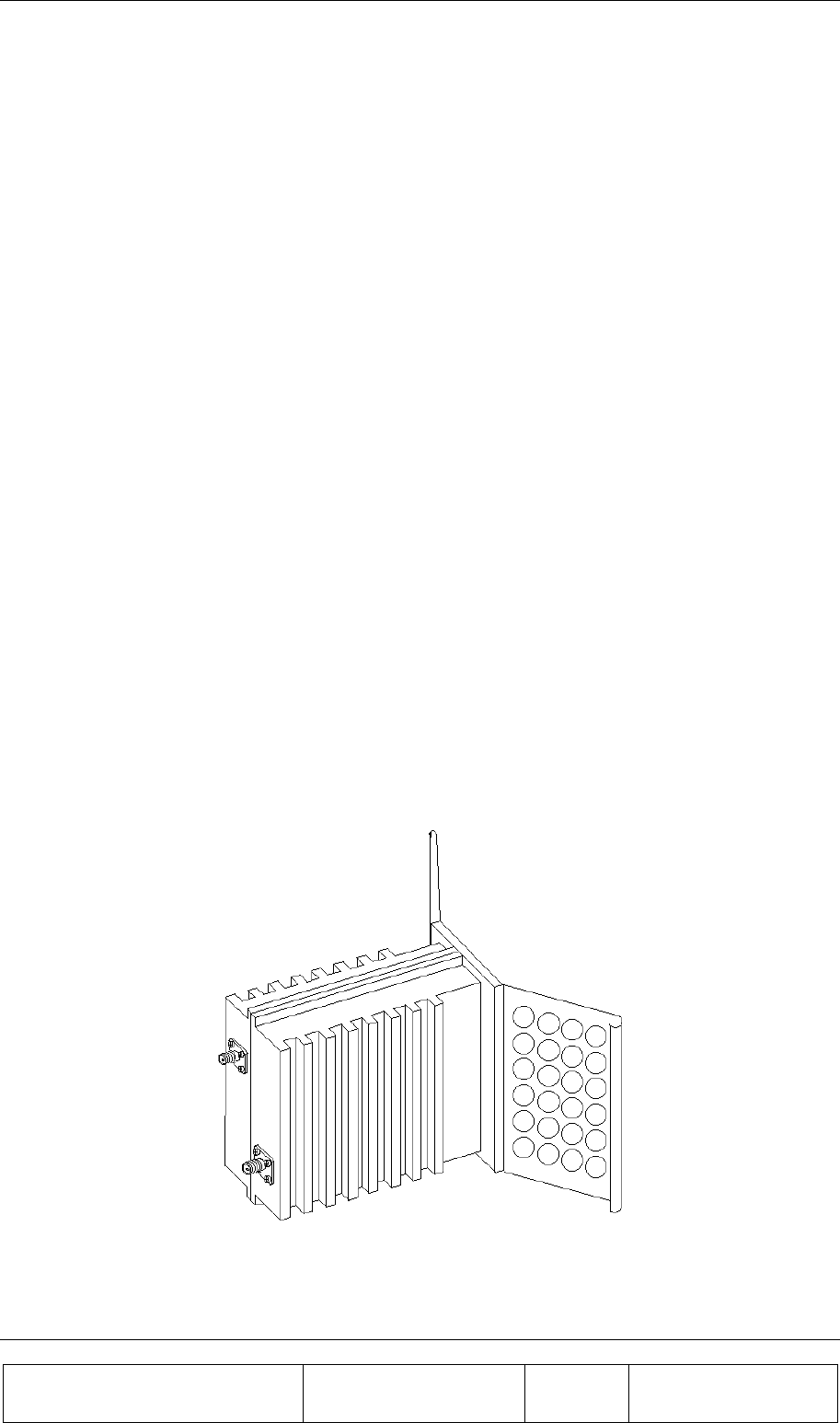
Figure 1: BEAMER (PCS band) with beam shaping wings 14
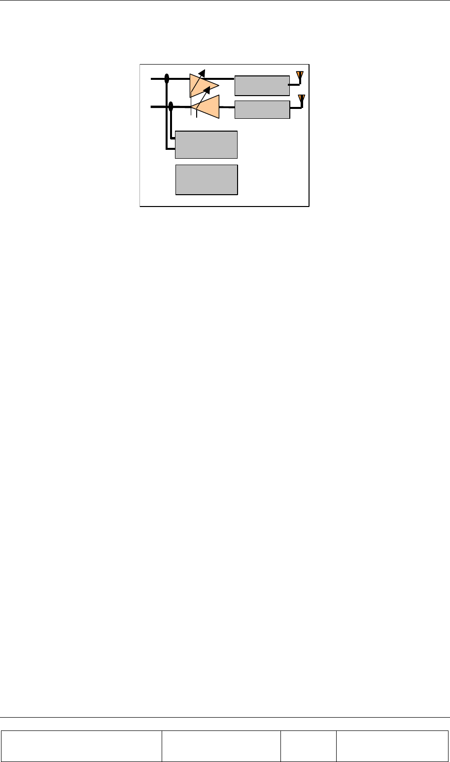
Figure 2: BEAMER block diagram 15
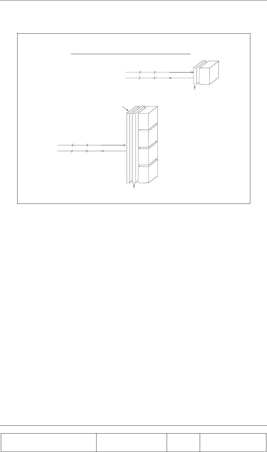
Figure 3: BEAMER family modular concept 16
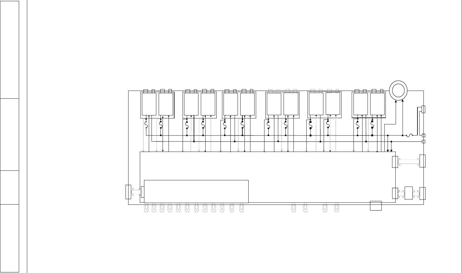
Figure 4: ICU block diagram 18
Figure 5: Active Bias-T block diagrams 19
Figure 6: Communication procedure 21
Figure 7: BEAMER 4X4X1 Pol. BEAMER array - front view 24
Figure 8: DC wiring 26
Figure 9: Fuse and backup battery location 26
Figure 10: Serial communication ports and on-board jumper locations 28
Figure 11: Bias-T inputs / outputs and numbering 29
Figure 12: Mounting Assembly. 32
Figure 13: BEAMER Array Mounting/Dismounting(Lower fork) 33
Figure 14: BEAMER Array Mounting/Dismounting (Upper fork) 34
Figure 15: BEAMER dismounting 35
Figure 16: Mounting Assy. 37
Figure 17: Bottom Array 38
Figure 18: Top Array 39
Figure 19: Beamer single pol. – sector connections block diagram 40
Figure 20: Beamer system entities and their logical relationships 41
Figure 21: Tx link budget example 50
Figure 22: Rx chanel gain distribution example 52


Proprietary Information
Title: BEAMER Array System-
Assembly and Operation Manual
Doc. No.: 913000000 Rev.: 00 Page: 11 of 92
TABLES
Table 1: RS485 and RS232 communication connectors 27
Table 2: BEAMER system logical addresses range 42
Table 3: ICU - BEAMER default values and quick reference 43
Table 4: BEAMER limits recommended settings 47
Table 5: ICU limits setting 48
Table 6: Failure conditions 48

Proprietary Information
Title: BEAMER Array System-
Assembly and Operation Manual
Doc. No.: 913000000 Rev.: 00 Page: 13 of 92
1. INTRODUCTION
This document is a guide to the Installation, operation and maintenance of the integrated Interface and
Control Unit (ICU) and the BEAMERTM Active Radiating Module System.
1.1. Acronyms and Abbreviations
ACPR Adjacent Channel Power Ratio
BEAMER™ Active Radiating Module
ATP Acceptance Tests Procedure
BFN Beam Forming Network
BPF Band Pass Filter
BTS Base Transceiver Station
BW Band Width
CDMA Code Division Multiple Access
DCA Digitally Controlled Attenuator
EMI Electro Magnetic Interference
FSK Frequency Shift Keying
ICU Interface & Control Unit
IM Inter Modulation
LED Light Emitting Diode
LSB Least Significant Bit
M&C Monitoring and Control
MSB Most Significant Bit
MTBF Mean Time Between Failures
INTRODUCTION
Proprietary Information
Title: BEAMER Array System
Assembly and Operation Manual
Doc. No.: 913000100 Rev.: 00 Page: 14 of 92
MTTR Mean Time To Repair
PCB Printed Circuit Board
PCS Personal Communications Services
RF Radio Frequency
RFI Radio Frequency Interference
Rx Receiver
TBD To Be Defined
TDMA Time Division Multiple Access
Tx Transmitter
VSWR Voltage Standing Wave Ratio
1.2. BEAMER Array System Overview
The BEAMER is an integrated active antenna for wireless communications. It incorporates a
transmission amplifier, transmission band filter, transmission elemental antenna, and the respective
receive chain: elemental antenna, band filter, and LNA.
The Tx amplifier is linearized. The Rx amplifier has an exceptional linear dynamic range. The
integral unit contains its own power conditioner and a monitoring and control circuit that
communicates with the BTS. The whole unit is sealed and built as a plug-in replaceable unit. The
design and production techniques offer low price and high reliability.
The BEAMER replaces the PA in the BTS. It circumvents the loss in the transmit chain - duplexer,
cable, antenna corporate feed or beam forming network – which typically amounts to 4 to 8 dB. A
column of 4 to 8 BEAMER units replaces the sector antenna. The reliability and the redundancy in the
array offer a major gain in life-cycle cost.
Figure 1: BEAMER (PCS band) with beam shaping wings
Dimensions: 70x140x160 mm
INTRODUCTION
Proprietary Information
Title: BEAMER Array System-
Assembly and Operation Manual
Doc. No.: 913000100 Rev.: 00 Page: 15 of 92
Band filter
Band filter
Micro-
Controller
Power
conditioner
PA
LNA
Figure 2: BEAMER block diagram
The antenna elements of the Tx and Rx channels are vertically and/or ± 45° slant polarized. The
separation between the receive and transmit antenna elements, and the resulting 20 dB of isolation,
enables the use of two separate band pass filters in front of the antenna elements instead of having to
use a much more complex diplexer structure.
The band pass filters (BPF) supply enough Tx/Rx channel isolation to ensure that the small amount of
Tx signal power and Tx wide band noise power leaking into the sensitive receive channel will not
degrade the Rx channel performance.
The Rx amplifier is a low noise amplifier with a high enough intercept point that several cellular
channels received simultaneously should not degrade each other's performance. The low noise and
high gain performance of this amplifier compensate for the high losses of the coaxial cable going
down from the Rx BEAMER front-end to the base station. The Tx Amplifier is a power amplifier that
enables up to 2 Watts average at the Tx antenna element of the BEAMER while compensating for
gain and power losses in the coaxial cable coming up from the base station.
1.2.1. BEAMER Family Modular Concept
The BEAMER family of products is modular. Each member can be attached to other modules to
establish a new product, matched to specific customer requirements. This concept is illustrated in the
following figure.
INTRODUCTION
Proprietary Information
Title: BEAMER Array System
Assembly and Operation Manual
Doc. No.: 913000100 Rev.: 00 Page: 16 of 92
BEAMER
CATV or
FIBER
Converters
(optional)
Tx Cable or Fiber
Rx Cable or Fiber
to Base Station
Tx Cable or Fiber
Rx Cable or Fiber
to Base Station
BEAMER
BEAMER
BEAMER
BEAMER
Corporate
Feed
CATV o
r
FIBER
Converters
(optional)
single
BEAMER
Multi BEAMER
High Gain
Antenna
Array
single BEAMERTM vs. Multi- BEAMERTM High Gain Antennas
Figure 3: BEAMER family modular concept
The BEAMER can be used as a standalone antenna element for distributed antenna purposes or
stacked to form an antenna array. The BEAMER and the BEAMER Array can be either connected
with a pair of coaxial cables to a modified base station or converted to match existing CATV
infrastructure or fiber optic infrastructure.
1.3. Overview of the Interface and Control Unit (ICU)
The BEAMER system consists of two parts:
• BEAMER Active Radiating Module Array System
• ICU (Interface and Control Unit) - the interface between the BTS (Base Transceiver Station) and
the BEAMER.
1.3.1. Interface and Control Unit - ICU
The ICU interfaces between the BEAMER system and the BTS, provides the BEAMER system with
the DC power, and controls each individual BEAMER within any array. It consists of a set of Bias T
connections for multiplexing the DC power and the monitoring and control communication on the RF
cables to the BEAMER system, a modem for communicating with each of the BEAMER units, and a
digital processor/controller.
The ICU interfaces to the Tx and Rx RF connections in the BTS, to the Alarm concentrating unit in
the BTS, and has serial ports for a local host computer, for remote control, and for diagnostics. A set
of indicator lights visually reports the status of each BEAMER Array. The ICU can be remote

INTRODUCTION
Proprietary Information
Title: BEAMER Array System-
Assembly and Operation Manual
Doc. No.: 913000100 Rev.: 00 Page: 17 of 92
controlled through an internal modem connected to a phone line and a remote host computer. The
Active Bias-Ts in the ICU enable setting the proper input power for the BEAMER and maintaining
beam shaping using the DCA inside the Active Bias-Ts. Up to 12 ACBTs , in any mixture of Rx and
Tx types can be assembled in each ICU
1.3.2. ICU Controller Description
The controller controls the proper operation of the BEAMER circuits and enables real-time bi-
directional communication between individual BEAMER units and the Base Station central computer
or dedicated computer, via the ICU. Up to 16 BEAMER modules can be monitored and controlled by
each ICU unit.
Bi-directional communication with the BEAMER is established through an FSK modulated
communication channel multiplexed on the Rx coaxial cable connecting the individual BEAMER, to
the ICU within the base station. The coaxial cable can be as long as 100 meters and have losses of up
to 10db at 1850-1990MHz band.
The Rx signal at 1850-1910 MHz runs on the same cable with DC and the M&C, but an isolation
between the DC, M&C, and Rx signals is high due to Bias-T isolation.
The Tx signal at 1930-1990 MHz runs on the same cable together with the DC voltage, but isolation
between the DC voltage and Tx signals is high due to Bias-T isolation.
INTRODUCTION
Proprietary Information
Title: BEAMER Array System
Assembly and Operation Manual
Doc. No.: 913000100 Rev.: 00 Page: 18 of 92
Figure 4: ICU block diagram
controller
CTRL DCA
CTRL Rx/Tx
F4F3
F2
Tx
bias T
#3
Rx
bias T
#4
Tx-i
n
Tx-o
ut
Array
#1
Rx-o
ut
Rx-i
nTx-i
n
Tx-o
ut
Array
#2
Rx-o
ut
Rx-i
n
sense sense sense
Array status
indications
CTRL DCA
CTRL Rx/Tx
CTRL DCA
CTRL DCA
Tx
bias T
#1
Rx
bias T
#2
To alarm
concentrating
unit
Return
+
-
F1
CTRL Rx/Tx
Fan
sense
24-28VDC
from
Power Supply
serial ports to
host
computer
J-3
J-1
J-5
J-4
POWER
ON
CPU
RUN
RS-485/RS-232
port
J-2
Tx
bias T
#11
Rx
bias T
#12
CTRL DCACTRL DCA
CTRL Rx/Tx
Tx-i
n
Tx-o
ut
Array
#3
Rx-o
ut
Rx-i
n
CTRL DCACTRL DCA CTRL Rx/Tx
Tx
bias T
#7
Rx
bias T
#8
Tx-i
n
Tx-o
ut
Array
#4
Rx-o
ut
Rx-i
n
CTRL DCACTRL DCA CTRL Rx/Tx
Tx
bias T
#9
Rx
bias T
#10
CTRL DCACTRL DCA
F5 F10
Tx-i
n
Tx-o
ut
Array
#5
Rx-o
ut
Rx-i
nTx-i
n
Tx-o
ut
Array
#6
Rx-o
ut
Rx-i
n
Array3 Array5 Array6 Array8Array2 Array4
sense sense
Modem
Interface
MODEM
DC Power
Switch
Tx
bias T
#5
Rx
bias T
#6
F16
F6 F7 F8 F9 F11 F17
Array7
Array1
sensesensesensesensesense
sense
Tx Rx
Com.
Array
#7 Array
#8 Array
#9 Array
#10 Array
#11 Array
#12
Array9Array10 Array11 Array12
I/O Card
INTRODUCTION
Proprietary Information
Title: BEAMER Array System-
Assembly and Operation Manual
Doc. No.: 913000100 Rev.: 00 Page: 19 of 92
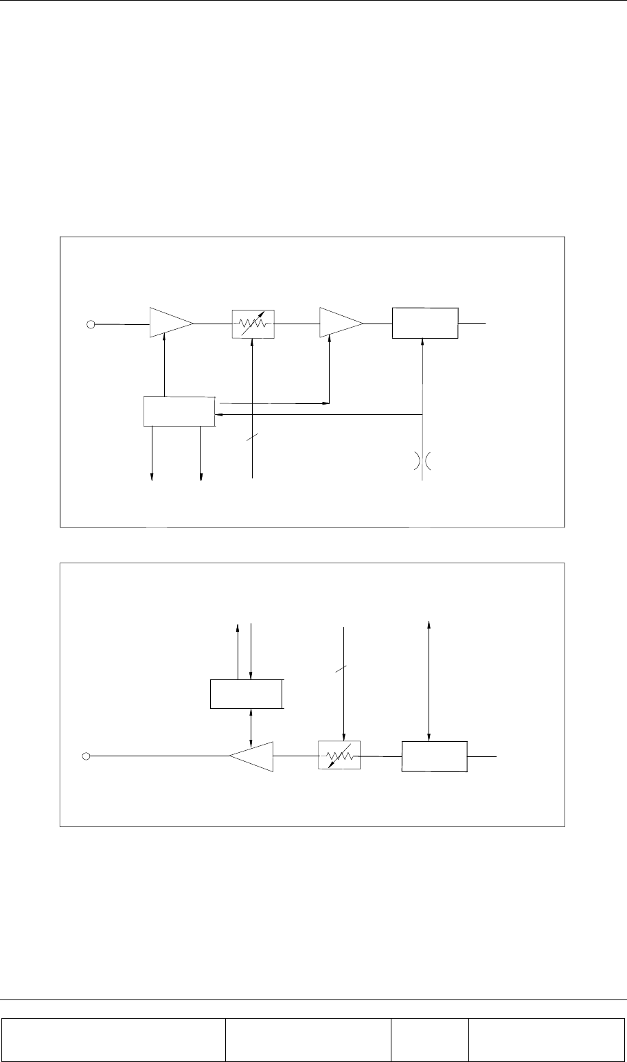
1.3.3. RF Path Description
1.3.3.1. Tx/Rx Active Bias-T Block Diagram
The Active Bias-T contents a boost amplifier and a digital controlled attenuator in order to adjust the
gain and enable a convenient interface to the BTS. The gain of the ABT assemblies is Temperature
Compensated. Block diagrams for this ABT are shown the following figure.
REGULATION
+PROTECT
P
A
LN
A
GAIN CONTROL
DUPLEXER
P
A
CURRENT
INDICATOR
GAIN CONTROL
5
DC Supply
RF + DC
+8V
to Rx
From BTS
Tx Output
To BEAMER
Array
Tx Active Bias-T Block
Rx Active Bias-T Block
P.
A
GAIN CONTROL
From
BEAMER
Array
RF + M&C
DUPLEXER
+8V
from Tx
Rx Amp
Current
Indicator GAIN
CONTROL
5
M&C Port
REGULATION
+PROTECT
To BTS
Rx Input
Figure 5: Active Bias-T block diagrams
1.3.4. Bias-T Types
The ICU is equipped with Rx ACBs and Tx ACBs. The Rx ABT can be one of several types, which
differ in the available gain from –4 db to +28db

INTRODUCTION
Proprietary Information
Title: BEAMER Array System
Assembly and Operation Manual
Doc. No.: 913000100 Rev.: 00 Page: 20 of 92
1.4. Communication with BEAMER and PC
1.4.1. Network Architecture and Capacity
The ICU is the master in a star configured network .The network shall enable data transmission along
the following data transmission paths:
1. ICU to each BEAMER unit of any of 3 Pol BEAMER Arrays
2. ICU to PC
3. BEAMER to ICU
The maximum capacity of the network is 16 BEAMER modules in any combinations of arrays.
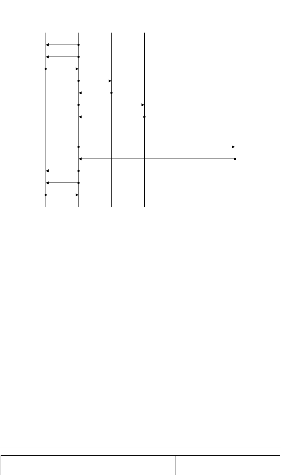
1.5. Communication Procedure
The communication mode between the ICU, the BEAMER, and the PC is half-duplex. The
communication procedure is described in the following figure:
1.5.1. BEAMER Monitoring and Control
BEAMER monitoring and control includes the following functions:
• Detect status of each BEAMER unit installed in a selected array.
• Receive indications from a selected BEAMER unit
• Manually control the selected BEAMER, for example, attenuator values and power amplifier
operation.
• Software downloads into BEAMER through the ICU.
INTRODUCTION
Proprietary Information
Title: BEAMER Array System-
Assembly and Operation Manual
Doc. No.: 913000100 Rev.: 00 Page: 21 of 92
PC ICU BEAMER #1
SEND DATA
COMMANDS
COMMANDS
STATUS
STATUS
SEND DATA
BEAMER #2 BEAMER#16
COMMANDS
STATUS
COMMANDS
STATUS
COMMANDS
STATUS
Figure 6: Communication procedure
1.6. DC Distribution
The DC supply to outdoor BEAMER arrays is obtained by connecting the DC power supply of the
BTS to the DC connections in the panel of the ICU. The DC voltage is supplied via the Tx and Rx
coaxial cable coming up from the ICU to the BEAMER unit or BEAMER beam forming network.
Power Source +24VDC to +28VDC
Max. Current Consumption Up to 450mA with no BEAMER arrays connected
Max. Current per BEAMER Up to 2Amp.
ICU Connectors
Tx Connector to BEAMER Array N-type connector, female
Tx Connector to Base Station Tx Port TNC connector, female
Rx Connector to BEAMER unit N-type connector, female
Rx connector to Base Station Rx Port TNC connector, female
Tx Control Connector 9 pin D-type connector
Rx Control Connector 9 pin D-type connector
DC Connector Molex, 10 PIN, 40A capability connector.
Grounding Connection By physically mounting the ICU with in the BTS

INTRODUCTION
Proprietary Information
Title: BEAMER Array System
Assembly and Operation Manual
Doc. No.: 913000100 Rev.: 00 Page: 22 of 92
1.7. Maintainability Requirements
The BEAMER family units including the ICU are designed as units for low Mean-Time-To-Repair
(MTTR). The Modular structure of the ICU enables the internal circuits to be easily approached and
replaced if found necessary.
Nevertheless, only an approved laboratory can do a full repair of an ICU or BEAMER unit, since such
a repair requires a full Acceptance testing.

Proprietary Information
Title: BEAMER Array System-
Assembly and Operation Manual
Doc. No.: 913000000 Rev.: 00 Page: 23 of 92
2. INSTALLATION GUIDE
2.1. Applicable Documents
• PC to ICU Protocol, version No.9450002XX
• BEAMER to ICU Protocol No.9450003XX
• BEAMER specifications No.9530003XX
• ICU specifications, Scope No.9530006XX
This document describes the installation of the BEAMER system, as integrated into Customer’s BTS.
2.2. Scope
This document describes the installation of the BEAMER System, as integrated into customer’s -BTS.
The BEAMER 1X4X4 Array System is basically a modular tower top LNA and power amplifier, with
programming and modularity features that are uncommon with other, comparable systems. It replace
the entire RF front-end of a PCS BTS and offers controllability and improved performance at reduced
size and cost.
The document details the instructions for programming and field installation of the BEAMER system.
It is intended to be used by customer technical personnel, who are trained to install and service the
BEAMER system.
2.3. Important Safety Precautions
The system is supplied following extensive acceptance production line tests. Usually, lab tests will
not be required before installing the unit at the customer's location. One should always be aware of
the necessary safety precautions, assuring that the BEAMER system will be fully functional after the
installation.
INSTALLATION GUIDE
Proprietary Information
Title: BEAMER Array System
Assembly and Operation Manual
Doc. No.: 913000100 Rev.: 00 Page: 24 of 92
Read this instruction guide thoroughly before starting with the installation. In case of doubt, do not
hesitate to call Celletra customer support engineering. Celletra support can be reached at the address
appearing at the beginning of this manual.
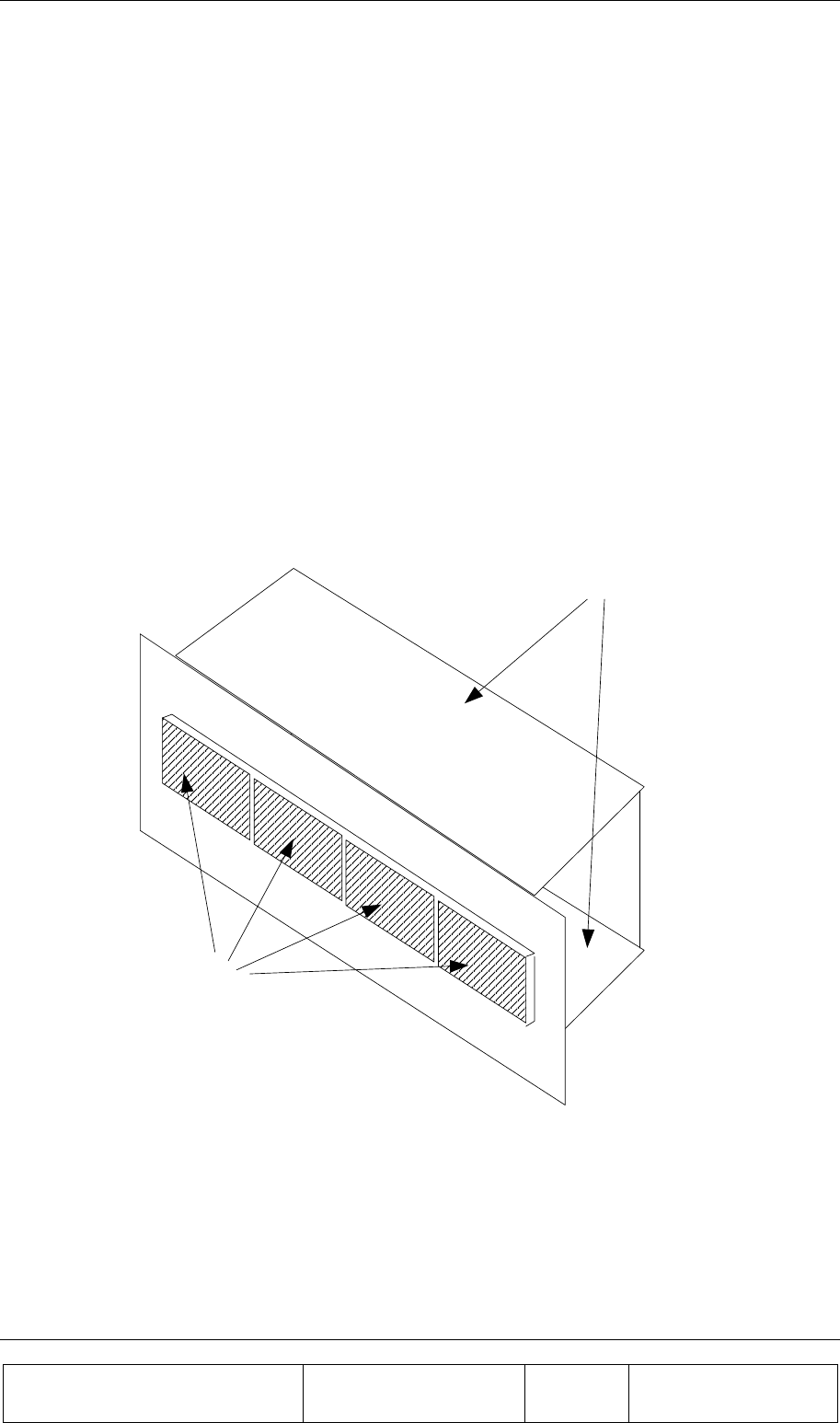
2.3.1. Handling and Moving the BEAMER Array
The BEAMER array is a delicate and accurate electrical apparatus.
Use extreme caution when handling the array. Always use the original box, with proper padding,
when delivering or moving the unit. The overall unit weight is ~25kg. If necessary, the array should
be carefully carried by two people, only for a short distance. BEAMER array hardware is hermetically
sealed in controlled environment. Do not open any radome covers or try to disassemble a BEAMER
module. This should be done only by Celletra authorized personnel. Do not paint the unit.
Never use adhesive tape on the radome surface, as this might severely affect the performance. Use
extra caution when installing the unit on tower top. Use proper winch to lift the unit up the tower.
Watch carefully for possible obstacles when lifting the unit. Pad the array, if needed, to avoid possible
damage during lift-up. Never place the array on the front panel, with the radomes facing down, as this
might cause radome breakage. Always place the unit on one of its sides.
Radomes
Side Walls
Figure 7: BEAMER 4X4X1 Pol. BEAMER array - front view
When installing the array always verify that the ICU power is OFF.
If it is not possible to turn the ICU power OFF (for example, when other sectors are connected to it),
remove the fuse connected to the active Bias-Ts serving the installed array. When replacing or re-
inserting the fuse in the ICU, always turn the ICU power OFF before removing the fuse cover.

INSTALLATION GUIDE
Proprietary Information
Title: BEAMER Array System-
Assembly and Operation Manual
Doc. No.: 913000100 Rev.: 00 Page: 25 of 92
2.3.2. System Measurement and Testing Conditions
Live +24VDC with high current capability exists on the Tx ABT output and the Rx ABT input (all the
N-type connectors at the ICU external RF interface). Use extreme care when handling these ports. It is
strongly recommended to disconnect the DC power to the ICU, whenever possible, before each and
every cable connection to the Tx ABT outputs or the Rx ABT inputs.
Always use a DC block device connected to the measuring equipment input or output ports (spectrum
analyzer, power meter, or RF signal source), when measuring ICU of BEAMER array performance.
Before applying RF power to any port of the system (either ICU or BEAMER array) always turn the
DC power ON. Never apply any RF input power with the unit's DC power OFF.
Do not apply more than +20dBm of RF input power to any RF port of the
BEAMER system, or irreversible damage may occur.
When measuring high power outputs, always verify that the equipment probe is capable for handling
the expected output power.
With DC power ON and the nominal RF input applied, BEAMER -Tx radiators produce 2Watts of RF
power per module, 8 Watts per array, and approximately 150Watts EIRP.
When testing the units in lab or during field installation, always practice RF
radiation safety rules.
During lab tests, with DC voltage applied to the array, do not use any PCS mobile transmitter in a
range of less than 10 meters from the BEAMER array. An unexpectedly high RF power might appear
at the Rx output, which might in turn damage the measuring devices connected to that port.
2.4. ICU Operation Instructions
2.4.1. DC Connections and Fuse Replacement
2.4.1.1. DC Wiring
The ICU should be connected to 24±4 VDC power supply. A minimum of 14AWG wires should be
used, for minimal DC voltage drop. The following diagram shows the DC connection to the MOLEX
DC connector. The three wires connected to each pin at the connector should be tied together as close
as possible to the DC voltage source.
INSTALLATION GUIDE
Proprietary Information
Title: BEAMER Array System
Assembly and Operation Manual
Doc. No.: 913000100 Rev.: 00 Page: 26 of 92
Figure 8: DC wiring
2.4.1.2. Fuse Replacement
Fuses are located under the fuse compartment panel on the front panel. To access the fuses, remove
the panel (2 screws). Tx fuse is 20Amp. Rx fuse is 5Amp.
The fuses are aircraft circuit breakers that can be used to turn off a whole sub-array.
Remember to disconnect the RF drive (or to turn the RF drive OFF) before turning the DC power
OFF.
Figure 9: Fuse and backup battery location
Conector view
from outside
24-28VDC
Ground
Circuit 1
Backup
Battery
Fuses

INSTALLATION GUIDE
Proprietary Information
Title: BEAMER Array System-
Assembly and Operation Manual
Doc. No.: 913000100 Rev.: 00 Page: 27 of 92
2.4.2. Connecting the Unit to a Host PC or BTS Controller
2.4.2.1. Serial Communication Connector
Communication with BTS controller RS232 connector interface is located on the left side of the
MOLEX DC connector on the rear panel. It is a standard 9-pin female D-type connector.
Table 1: RS232 communication connector
Pin # RS232
1 NC
2 Rx Data
3 Tx Data
4 NC
5 Ground
6 DSR
7 RTS
8 CTS
9 NC
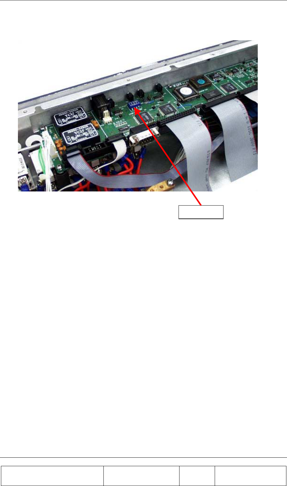
2.4.2.2. Communication Mode
The communication mode at the ICU controller board is enabled for RS232 by the communication
switch is SW1at OFF position. Four switches are located on this SW1, used for other ICU settings.
Caution: The user should not change the setting of these switches, unless
specifically advised by Celletra. An unauthorized, uncontrolled change of these
switches might produce unpredictable system behavior.
The RS232/RS485 DIP switch is the last switch at the far-left side of the PCB, when viewed from the
ICU front, as shown in the following figure.
INSTALLATION GUIDE
Proprietary Information
Title: BEAMER Array System
Assembly and Operation Manual
Doc. No.: 913000100 Rev.: 00 Page: 28 of 92
Figure 10: Serial communication ports and on-board jumper locations
It is possible to communicate with the unit via the RS485, using a commercial RS485-RS232
converter. As an example, ADAM-4520 from Advantech can be used for this purpose.
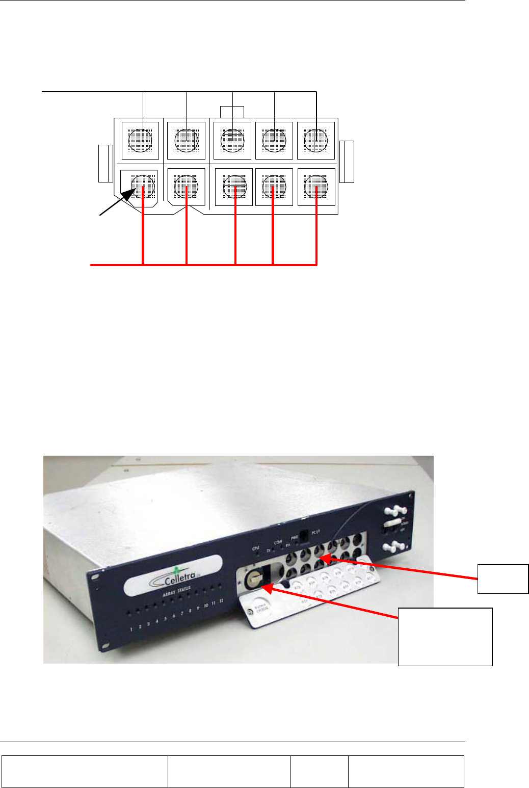
2.4.3. Replacing the Back-Up Battery
The ICU controller board is equipped with 3Volt battery, used for NVRAM and real-time clock keep-
alive function. Under normal operating conditions, this battery should be replaced every three years.
Failure to replace the battery will result in loss of the configuration data and the real-time clock
setting, following power down. Although this is not critical, we recommend changing the battery once
every 2 years, or at every scheduled maintenance.
Before changing the battery, record the ICU configuration. We recommend creating a batch file,
within the BTS controller software, to reload the original ICU configuration after battery replacement.
To access the battery, turn off the ICU. Remove the ICU front cover. The battery opening is located
on the left side panel under the RS-232 connector. Use a small screwdriver to carefully push the
battery out. Insert a 3Volt, CR2032 type Lithium battery. The + side of the battery should be pointing
to the side panel. Reinstall the front cover.
It is possible to replace the battery under live DC voltage applied to the ICU, if one does not wish to
interrupt the BTS operation, even during scheduled maintenance. In this case, you should use extreme
care not to short the ICU controller circuitry.
Jumpers
INSTALLATION GUIDE
Proprietary Information
Title: BEAMER Array System-
Assembly and Operation Manual
Doc. No.: 913000100 Rev.: 00 Page: 29 of 92
2.4.4. Bias-Ts
In this manual, Bias-Ts are also termed 'sub-array', since each Bias-T can serves an independent
portion of an array (i.e., Tx sub-array or Rx1 and Rx2 sub-arrays, which are all physically part of the
same array, but are logically independent entities).
The Bias-Ts serve four purposes:
1. Supply DC voltage to the BEAMER modules within the sub-array.
2. Provide DCA controlled RF amplification stage, to overcome possible RF distribution losses
and to provide control on the transmitted or received output power per sub-array.
3. Connect the BEAMER modules Telemetry to the ICU controller via the superimposed FSK
link.
4. Enable the S/W downloading to each BEAMER of the array using the Telemetry channel.
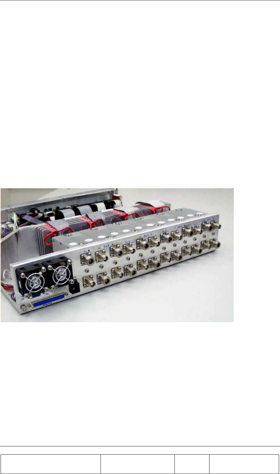
The sub-array direction of the ICU Bias-T connector is N-type connector, capable of supporting the
DC current to the sub-array. The BTS side is TNC type connector. The following figure shows the
active Bias-T location on the ICU.
Figure 11: Bias-T inputs / outputs and numbering
Viewed from right to left, the Bias-Ts are organized as:
[Rx1-Rx2-Tx], [Rx1-Rx2-Tx], [Rx1-Rx2-Tx], [Rx1-Rx2-Tx]
Bias-T number 1 is on the far right going to Bias-T number 12 at the near left. These (physical)
numbers also serve as logical addresses for the Bias-T (sub-arrays) at the system setup.
In case less arrays are integrated in the system, the number of Bias-Ts will be reduced.

INSTALLATION GUIDE
Proprietary Information
Title: BEAMER Array System
Assembly and Operation Manual
Doc. No.: 913000100 Rev.: 00 Page: 30 of 92
2.5. Array Installation
The BEAMER array provides coverage of ±45° for the azimuth, ±7° for the elevation at –3dB points.
A mechanical tilt, continuous up to 15° is provided. We recommend using a 3-4 inch diameter pole
for the array installation. The figures later in this section illustrate the installed array with the doors
open, showing the Tx and Rx cables connections.
The unit should be connected to the main RF cables feeding the array. The RF lines should have total
RF loss of less than 8 dB and a DC resistance lower than 0.2 Ohms, for 50 meters long cable. 3/8” or
1/2" or 5/8" cable can be used. When connecting these cables to the array on one side and to the ICU
on the other, use proper moisture sealing methods, if required depending on the connector type used.
Sealing and weatherproofing of RF connector is of prime importance to assure good electrical contact,
minimizing DC loss and passive RF inter-modulation effects. Thus, special care should be taken with
the RF connectors sealing and weatherproofing especially at the array input connectors that are
exposed to extreme environmental conditions. Common sealing practice should be used.
For sealing instructions, refer, for example, to Andrews weatherproofing recommendations with
3MTM Cold ShrinkTM Weatherproofing Kit, or an equivalent sealing method.
Before installing the BEAMER array, note that each array has a Tag attached to it. After installation
remove the tag and keep it. This tag carries the BEAMER modules address and location within the
array.(This address is the serial number of each BEAMER unit as appear on the module label nearby
the Rx connector).You will need these IDs later, for system configuration setup.
2.6. Assembly Instructions for the PCS 1x4x4 Array
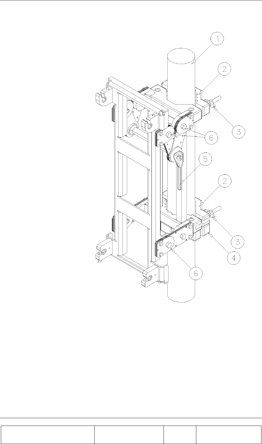
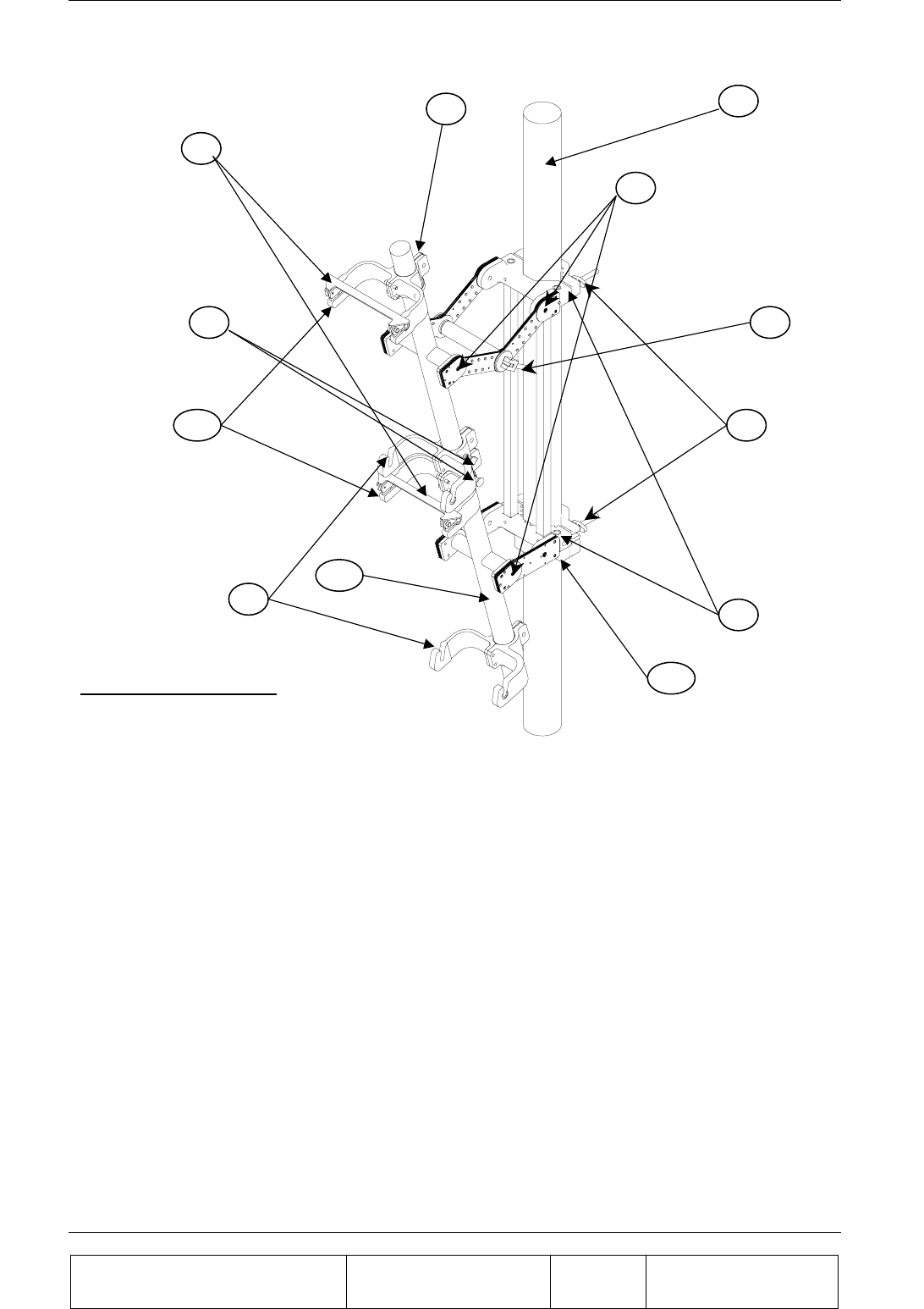
2.6.1. Mounting Assembly (Figure 12):
1. Mount the securing clamps (4) on the pole (1) at the location approx. close to the bottom side
mounting assembly. Tighten the screws using 9/16 wrench.
2. Mount the mounting assembly on the pole (1) and secure the two clamps (2) with the wing nuts
(3). Tighten the four wing nuts (3) using 9/16 wrench.
3. Adjust azimuth:
One. Loosen the 4 wing nuts (3) and rotate till you have reached the required azimuth.
Two. Tighten the 4 nuts (3).
4. Adjust elevation:
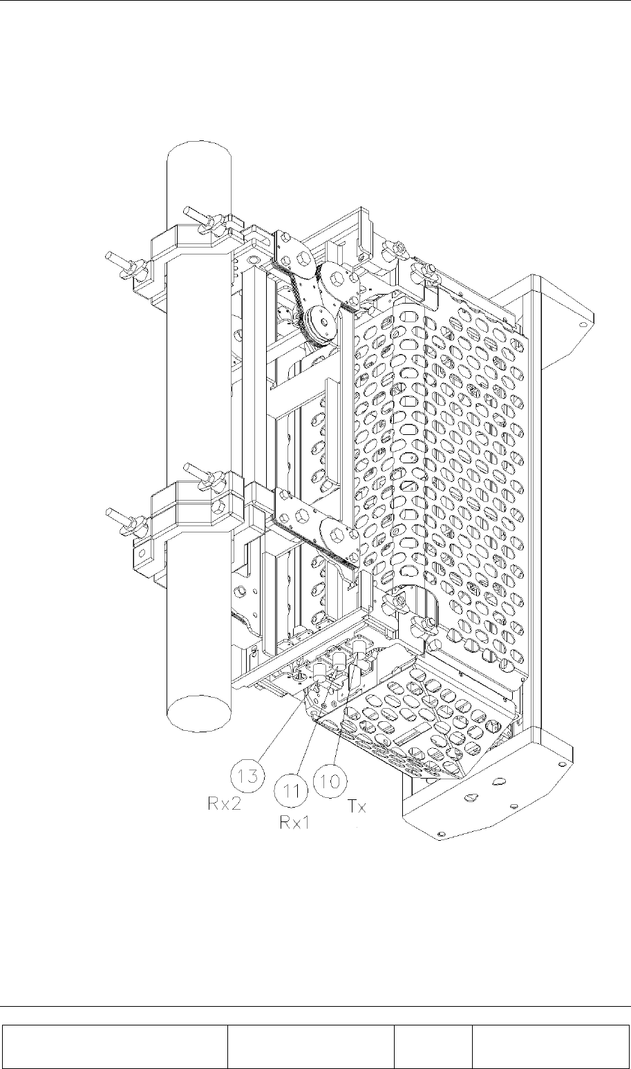
One. Loosen the 6 bolts (6) (on both sides of the mounting assembly).
Two. Release the latch (5) and adjust the tilt. Once the tilt is set, lock in position using the
latch (5).
Three. Tighten the bolts (6).
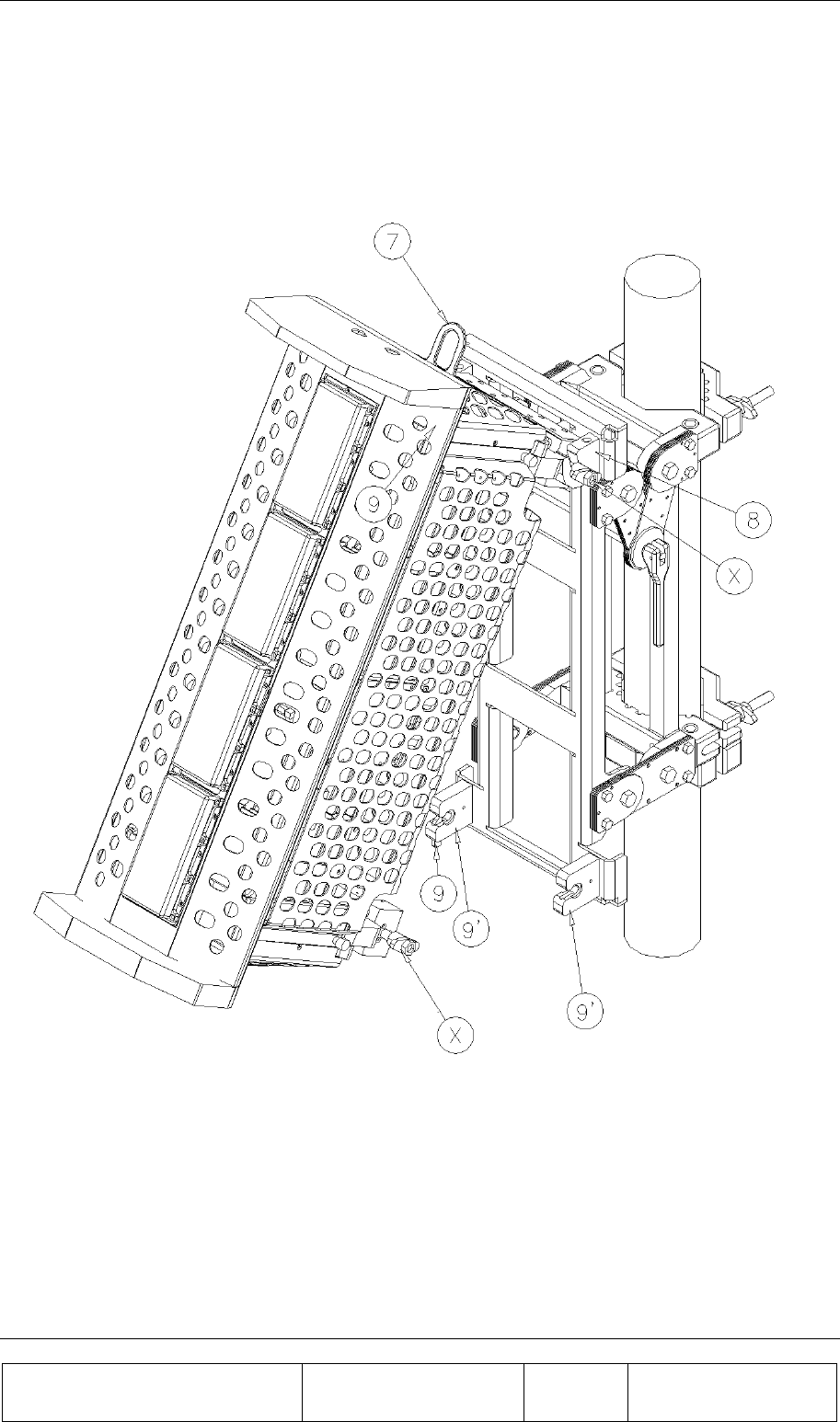
2.6.2. BEAMER Array Mounting (Figures 13 and 14):
1. While the BEAMER array is hanging by the lifting hook (7) put the BEAMER array on the
lower fork (8) of the mounting assembly.

INSTALLATION GUIDE
Proprietary Information
Title: BEAMER Array System-
Assembly and Operation Manual
Doc. No.: 913000100 Rev.: 00 Page: 31 of 92
2. Push the upper section of the BEAMER array until its upper bolts engage the upper forks (9) of
the mounting assembly and secure them with the lever (9).
3. Tighten the 4 wing nuts (X) using 9/16 wrench.
4. Connect the Rx1, Rx2, Tx and grounding cables (10-13).
2.6.3. BEAMER Array Dismounting (Figures 13 and 14):
1. Insert the winch cable hook through the bracket(7) located on top of the array.
2. Disconnect the Rx1, Rx2, Tx and grounding cables.
3. Release the 4 wing nuts |(X).
One. Release the module from its upper forks (9’) by pushing the lever (9) and rotating the
array approx. 30 deg. downward around the lower forks (8).
4. Remove the array by lifting it and pulling it out from the lower forks (8).
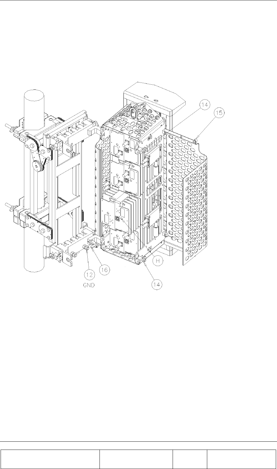
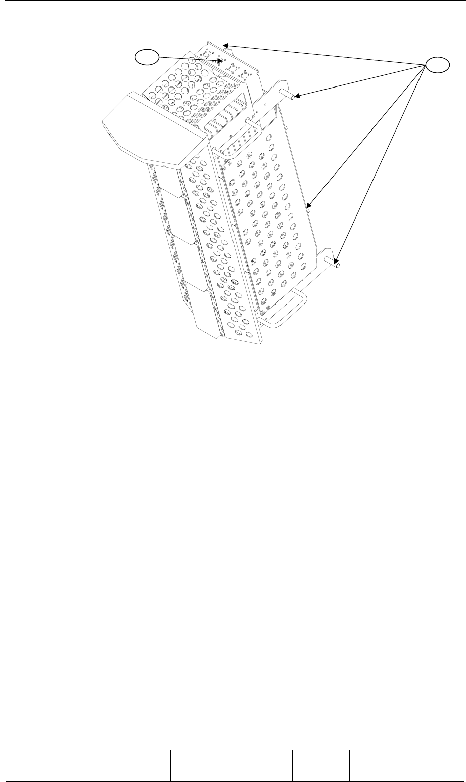
2.6.4. BEAMER Dismounting (Figure 15):
1. Release 2 wing nuts (14), rotate the BEAMER assembly until it stops with a “click” latch.
2. Open the right hand door by releasing 2 thumb screws (15).
3. Dismount the BEAMER by disconnecting its Rx and Tx connectors, then insert a Phillips
screwdriver (#6x300 mm) through holes “H” to engage the screws (6 captive screws for each
BEAMER).
4. Dismount BEAMER “A” by first dismounting the lower roof (RL) by removing 6 screws (4-40
UNC Phillips flat 100 deg.). Dismount BEAMER “D” by first dismounting the upper roof (RU)
and the lifting hook (7) by removing 6 screws (4-40 UNC Phillips flat 100 deg.). BEAMERs
“B” and “C” can be dismounted directly.
2.6.5. BEAMER Mounting (Figure 15 and 16)
1. To mount BEAMER “A”, the lower roof (RL) should be dismounted. Engage the BEAMER
“A” in place and secure its 6 captive screws with the long screw driver (Phillips #6 x300 mm),
mount the lower roof (RL) and secure it with 6 screws (4-40 UNC Phillips flat 100 deg.),
connect the Rx and Tx connectors.
2. BEAMERs “B” and “C” can be mounted directly by using the long screw driver. Connect the
Rx and Tx connectors.
3. To mount BEAMER “D”, the upper roof (RU) and the lifting hook (7) should be dismounted.
Engage BEAMER “D” in place and secure its 6 captive screws with the long screw drivers. Put
the lifting hook (7) in place then mount the upper roof (RU) and secure it with 6 screws (4-40
UNC Philips flat 100 deg.), Connect the Rx and Tx connectors.
4. After the BEAMERs are secured in place, close the right hand door by securing the thumb
screws (15).
5. Release the BEAMER assembly. By pushing button (16) (Fig. No. 16) downward, rotate the
array and secure the wing nuts (14) in place.
INSTALLATION GUIDE
Proprietary Information
Title: BEAMER Array System
Assembly and Operation Manual
Doc. No.: 913000100 Rev.: 00 Page: 32 of 92
Figure 12: Mounting Assembly.
INSTALLATION GUIDE
Proprietary Information
Title: BEAMER Array System-
Assembly and Operation Manual
Doc. No.: 913000100 Rev.: 00 Page: 33 of 92
Figure 13: BEAMER Array Mounting/Dismounting (Lower fork)
INSTALLATION GUIDE
Proprietary Information
Title: BEAMER Array System
Assembly and Operation Manual
Doc. No.: 913000100 Rev.: 00 Page: 34 of 92
Figure 14: BEAMER Array Mounting/Dismounting (Upper fork)
INSTALLATION GUIDE
Proprietary Information
Title: BEAMER Array System-
Assembly and Operation Manual
Doc. No.: 913000100 Rev.: 00 Page: 35 of 92
Figure 15: BEAMER dismounting

INSTALLATION GUIDE
Proprietary Information
Title: BEAMER Array System
Assembly and Operation Manual
Doc. No.: 913000100 Rev.: 00 Page: 36 of 92
2.7. PCS 1x8x8 Array Assembly Instructions
1. Mount the securing clamps (12) on the pole (1) at the location approx. close to the
bottom side of the mounting assy. Tighten the wing nuts using 9/16 wrench
2. Mount the Mounting assy. On the pole (1) and secure the clamps (2) with the wing nuts
(3). Tighten the wing nuts using 9/16 wrench
3. Untighten the bolts (6) a bit so the hanging arms (7)&(11) are free to swivel around the
secondary pole (10).
4. Pull the plunger (8) and turn the bottom set of (7)& (11) counterclockwise until the
plunger (8) locks in place about 60 deg of the center position.
5. Pull the plunger (8) and turn the top set of (7)& (11) clockwise until the plunger (8)
locks in place about 60 deg of the center position.
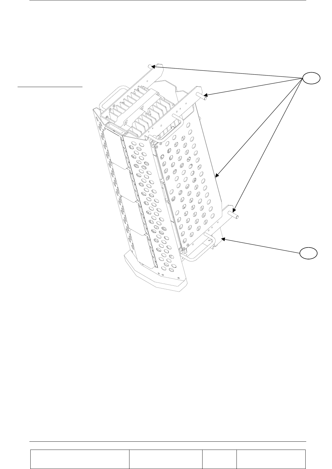
6. Insert the arrays threaded pins (13) for the bottom and (15) for the top at the groove of
the lower forks (7) and then press the top threaded pins in place at the upper forks (11).
Make sure the latch(9) turns up and then falls back in place to secure the top pins of
(13)&(15)
7. Tighten the wing nuts of all the pins (13)&(15). Using 9/16 wrench.
8. Release the plungers (8) and rotate the antennas back in place.
9. Tighten the bolts(6) using 9/16 wrench
10. Connect the Rx and Tx Cables coming out of the rear divider which is
mounted on the lower half of the secondary pole(10) to the top (16) and
bottom(14) connector flanges.
11. To adjust the Azimuth :
12. Untighten the wing nuts (3) and rotate till you have reached the position .
13. Tighten the nuts (3).
14. To adjust the tilt of the antenna :
15. Untighten the 6 bolts (4) (on both sides of the mounting assy).
16. Release the latch(5) and adjust the tilt , once the tilt is set lock in position using the
latch(5).
17. Tighten the bolts (4) .
INSTALLATION GUIDE
Proprietary Information
Title: BEAMER Array System-
Assembly and Operation Manual
Doc. No.: 913000100 Rev.: 00 Page: 37 of 92
Figure 16: Mounting Assy.
9
8
61
3
10
7
5
2
4
11
12
Mounting Assy
INSTALLATION GUIDE
Proprietary Information
Title: BEAMER Array System
Assembly and Operation Manual
Doc. No.: 913000100 Rev.: 00 Page: 38 of 92
Figure 17: Bottom Array
Bottom Array 13
14
INSTALLATION GUIDE
Proprietary Information
Title: BEAMER Array System-
Assembly and Operation Manual
Doc. No.: 913000100 Rev.: 00 Page: 39 of 92
Figure 18: Top Array
2.8. Beamer System Setup
2.8.1. System Block Diagram
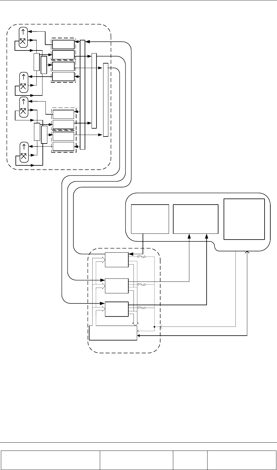
The following diagram shows the system connection for a single sector Pol. BEAMER array. A single
ICU can support up to four sectors, each connected as described in the figure.
Top Array 15
16
INSTALLATION GUIDE
Proprietary Information
Title: BEAMER Array System
Assembly and Operation Manual
Doc. No.: 913000100 Rev.: 00 Page: 40 of 92
Micro-BTS
ICU Controller Board
Splitter
PolBeamer - 4x1 Array
Beamer -
Rx
Combiner
Beamer -
Tx
Beamer -
Rx
Beamer -
Tx
Combiner
Beamer -
Rx
Combiner
Beamer -
Tx
Beamer -
Rx
Beamer -
Tx
Combiner
Combiner
Combiner
ABT - Tx
ABT - Rx
Rx2
Rx1
Tx
ABT - Rx
24VDC
Monitoring
Control
Host / BTS
interfaces
Interface and Control
Unit (ICU)
BTS
Up-Converter BTS
Down-Converter BTS Controller
RF Cables
Tx
Rx1
Rx2
Tx
Rx1
Rx2
Figure 19: Beamer single pol. – sector connections block diagram
The sector is configured as pol. BEAMER configuration, in which two Rx channels are used for
polarization diversity reception and one Tx channel is used for transmission. Other Configurations are
easily implemented.
INSTALLATION GUIDE
Proprietary Information
Title: BEAMER Array System-
Assembly and Operation Manual
Doc. No.: 913000100 Rev.: 00 Page: 41 of 92
2.8.2. Logical Addresses and System Components
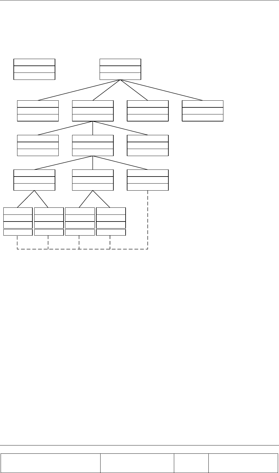
The BEAMER system setup treats the system block diagram as a hierarchy tree, with the BTS at the
top and the BEAMER modules at the bottom.
Figure 20: Beamer system entities and their logical relationships
The figure above shows the logical entities for a BEAMER system. The top left block can be used as
a legend: each entity is defined by its name, its available address range, and its actual address.
The figure shows a BTS, connected to four ICUs. Each ICU is connected to three physical arrays (for
simplicity, the tree is expanded for one ICU and one array only). Each array consists logically of three
sub-arrays (Bias-Ts): two Rx sub-array and one Tx sub-array. Each Rx sub-array connects logically to
two Rx BEAMER controllers. This connection logically controls both the BEAMER Rx board and the
BEAMER Tx board. The Tx sub-array has a dummy logical relation with the Tx- BEAMER module,
since its actual logical control is via the Rx- BEAMER block (this relation is shown as dashed line).
However, the Tx- BEAMER has actual physical relation with the Tx sub-array, by virtue of the RF
connection between them.
The actual logical addresses shown on the figure were chosen from the available address range and
are actually arbitrary. However, with the ICU Bias-T organization it is easier to group the Bias-Ts as
Rx1,Rx2,Tx per array. In other words, the following sub-arrays groups should be assigned for each
array (sector):
• Sub-arrays (1,2,3) - array #1
• Sub-arrays (4,5,6) - array#2
• Sub-arrays (7,8,9) - array#3
• Sub-arrays (10,11,12) - array#4
Entity Name
Address Range
Actual Address
BTS Controller
---
---
ICU
01-04
02
ICU
01-04
01
ICU
01-04
03
IDU
01-04
04
Beamer array
1-12
02
Beamer array
1-12
03
Beamer array
1-12
01
Sub-Array - Rx
1,2,4,5,7,8,10,11
2
Sub-Array - Rx
1,2,4,5,7,8,10,11
1
Sub-Array - Tx
3,6,9,12
3
Beamer-Rx
1-16
4
Beamer-Tx
Beamer-Rx
1-16
3
Beamer-Tx
Beamer-Rx
1-16
2
Beamer-Tx
Beamer-Rx
1-16
1
Beamer-Tx

INSTALLATION GUIDE
Proprietary Information
Title: BEAMER Array System
Assembly and Operation Manual
Doc. No.: 913000100 Rev.: 00 Page: 42 of 92
The following table summarizes the available address range for the system entities:
Table 2: BEAMER system logical addresses range
Name Address range
ICU 01 to 04. Address 00 reserved for testing
Array 01 to 12(03). For Micro- ICU: maximum 03 (always pol. BEAMER)
Sub-array (Bias-T) 01 to 12(09). For Micro- ICU: Same as physical address, maximum 09.
BEAMER 01 to 16. Address 00 reserved for testing
2.8.3. System Configuration and Setting
Some of the ICU setup are already configured for the needed system configuration. This setup is
saved on the ICU's Flash memory. Using the PC to ICU protocol commands, you can verify that the
ICU is properly set.
The following sections will guide you through the process of ICU setup verification. You can modify
the setup to match your configuration at any time.
Throughout this section, some command examples and data will be used. As a rule, all commands
data and commands codes are given here in decimal representation, unless specifically specified,
using 'H' prefix for hex numbering. Also, it is assumed that the reader has some knowledge with the
PC to ICU protocol, given in [1]. The command sequence described in this section should be referred
to as a system configuration guide, not as a PC to ICU programming manual. For more information,
refer to the applicable documentation listed at the beginning of this chapter.
Before setting up the system, avoid connect RF cables between the ICU and the BEAMER array.
Since the Tx and Rx gain are not calibrated yet, this is done to protect the BTS interface and the
BEAMER array from overdrive conditions.
The following table can be used as a reference for the ICU and BEAMER array setting. The table
specifies the pre-set default values and points to the specific command code, used for reading or
saving a parameter value.
Note: Many values are not set. The following sections will instruct you how to set
these values, tailored to the specific on-site installation.
Caution: some values ( such as RS-232/RS-485 switch ,Time out and codes
1,137,141,145-149) are factory set and should not be changed on location. In part
ICU are, these values relate to the BEAMER array calibration and operation
modes. Modification of these values, without coordination and specific
authorization from Celletra engineering, can cause invalid array performance and
should be avoided. The changes are possible by the highest password
authorization only.

INSTALLATION GUIDE
Proprietary Information
Title: BEAMER Array System-
Assembly and Operation Manual
Doc. No.: 913000100 Rev.: 00 Page: 43 of 92
Table 3: ICU - BEAMER default values and quick reference
Parameter Save
code Read
code Data bytes default value Required for µ
µµ
µICU
Operation Mode 05 06 00-Auto 00-Auto
Control Mode 07 08 00-Main, 01-Local 00-Main, 01-Local
ICU configuration
(jumper
positions)
N/A 09 01-Operation
01-I/O installed
00-MODEM not installed
00-RS-232/RS485 disabled
01-Operation
00-I/O not installed
00-MODEM not installed
01-RS-232/RS485 enabled
System Features 10 11 Not set # of arrays - 03
arrays type BEAMER -00
Array
configuration
12 13 Not Set See 2.8.3.2
Bias-T
configuration
14 15 Not Set See 2.7.3.3
Bias-T type 16 17 01 01 02 01 01 02 01 01 02
01 01 02
02-Tx 01-Rx
00-Not installed
01 01 02 01 01 02 01 01 02
00 00 00
See also 2.8.3.4
Bias-T
attenuation
18 19 Not set See 2.8.4
BEAMER limits 20 21 Not set See 2.8.4.4.1
ICU limits 22 23 Not Set See 2.8.4.4.2
Bias-T limits 24 25 Not Set See 2.8.4.4.2
Alarm Conditions 26 27 Not Set See 2.8.4.4.4
Time out 36 37 BEAMER - 128mSec
ICU - 5 minute
Do not change. Cannot be
accessed in operation
mode.
Real time clock 38 39 Set to Israeli time zone Set to location time zone
BEAMER
configuration
133 134 All ON. Attenuation = 0dB. All ON. See 2.8.4.3
Shut-down
conditions
135 136 All ON All ON. See 2.8.4.4.3
Other BEAMER
parameters
1, 137, 141,
145-149
Factory set. Not intended to be changed on location!
These commands cannot be accessed in operation mode.
The following sections describe how to configure the system step-by-step.

INSTALLATION GUIDE
Proprietary Information
Title: BEAMER Array System
Assembly and Operation Manual
Doc. No.: 913000100 Rev.: 00 Page: 44 of 92
2.8.3.1. Set ICU Operation Mode
The ICU configuration setup can only be changed when the ICU is set to SLAVE mode. The default
ICU configuration is AUTO. To switch to slave mode use 'save operation mode' command (code 05),
with parameter 01. Note, however, that if the ICU communication is left unattended for longer than
the time out, defined by 'save time out' command (code 36) [default value is 5 minute], the ICU will
automatically switch back to AUTO mode. Only the following commands are available in AUTO
mode:
• Save operation mode (05)
• Read operation mode (06)
• Save control mode (07)
• Read control mode (08)
• Read array status (28)
• Read BEAMER status (29)
• Read ICU status (30)
In AUTO mode, any other command will be responded by an error message (code 34, data 01 xx xx
xx xx).
2.8.3.1.1. Checking the ICU System Address and ICU ID
The ICU system address and the ICU ID can be easily modified1, to suit your needs. To change the
ICU address you should know the ICU ID.
You can read the ICU system address and its ID as follows:
Sent
command Code Data Response from ICU Remarks
Read ICU ID 02 00 X1 X2 X3 X4 Every ICU answers when
addressed by 00
Read ICU
system
Address
04 X1 X2 X3 X4 X1 X2 X3 X4 Y Use ICU ID (X1 X2 X3 X4) to
find ICU address (Y)
2.8.3.1.2. Changing the ICU System Address
Caution: ICU ID is located on the unit label. The unit label is attached to the -ICU
front panel (the fuse panel). The ICU ID is its physical number. Do not modify the
ICU ID, unless authorized by Celletra engineering support.
Once the ICU ID and system address are known, you can easily modify the system address to any
other value. The following sequence demonstrates how to change the ICU system address from Y to
04, using known ICU ID 101 102 103 104.
1 ICU ID cannot be changed in operation mode. Issuing command code 01 in operation mode will produce an
error message.

INSTALLATION GUIDE
Proprietary Information
Title: BEAMER Array System-
Assembly and Operation Manual
Doc. No.: 913000100 Rev.: 00 Page: 45 of 92
Sent
command Code Data Response
from
ICU
Remarks
Save ICU
system
address
03 101 102 103 104 04 ACK Change system address from Y to 04
using known ID 101 102 103 104
Note: ICU system address ranges between 01 to 04. ICU address 00 is reserved
for system configuration and should not be used.
2.8.3.2. Configuring the Number of BEAMER Arrays
The 'save system features' command is used to configure the number of connected BEAMER arrays.
Use this command to add or remove an array (logically) from the system. To set the number of
installed arrays to 2, use:
Code 10 (save system features), ICU address, 02, 00 (BEAMER)
Note: Issuing the 'save system features' command will erase the previous BEAMER
configuration. Previous definitions of arrays and Bias-T assignments must be
reprogrammed, following this command.
2.8.3.3. Bias-T Definitions
Once the arrays are configured, a Bias-T must be assigned for each array. 'Save Bias-T configuration'
command (code 14) is used for assigning the Bias-T for the arrays. For example, the following
command assigns Bias-T #1, 2, and 3 to array #1:
Code 14 (save Bias-T configuration), ICU address, 01 (array address), 07 00 (Bias-T #1,2,3 assigned)
Bias-T addresses and Bias-T physical locations are the same (i.e. Bias-T number 1 is mapped to Bias-
T address 1, and so forth).
Note: Bias-T assignment is bit-wise representation of the command data bytes. Also note that the
above command does not configure the Bias-T type (Tx or Rx). Repeat for every installed array in the
system.
2.8.3.4. Configuring the Bias-T Type
Using the command 'save Bias-T type' (code 16) will define the Bias-T type for the ICU (note that this
logical definition must agree with the actual, physical Bias-T type, as installed at the ICU. For ICU,
this is always Rx-Rx-Tx-Rx-Rx-Tx-Rx-Rx-T- right to left, form the rear). This logical definition does
not change for the ICU.
The following example defines ICU Bias-T installation:
Code 16 (save Bias-T type), ICU address, 01 01 02 01 01 02 01 01 02 01 01 02 02
Note: For Bias-Ts not installed, thus will appear as 00.
2.8.4. Setting the Bias-T Attenuation
Bias-T attenuation, for either Rx or Tx Bias-T, can be modified with the command 'save Bias-T
attenuation' (code 18). Command 'read Bias-T attenuation' (code 19) can read these settings.

INSTALLATION GUIDE
Proprietary Information
Title: BEAMER Array System
Assembly and Operation Manual
Doc. No.: 913000100 Rev.: 00 Page: 46 of 92
Example: To change the Bias-T attenuation for Bias-T #3 (in this case, a Tx Bias-T) to 12dB (=24 or
18H), use the following command:
Code 18 (save Bias-T attenuation), ICU address, 03, 18H
2.8.4.1. BEAMER Array Module Registration
The command 'save BEAMER system address' (code 131) registers BEAMER module with ID # AA
BB CC DD with system address SS. The BEAMER module ID can be located on the BEAMER
module label. An unknown BEAMER ID can be found by issuing a 'read BEAMER system address'
command, with address 00. Note however that since every installed BEAMER module will respond to
address 00, it is impossible to issue this command for an array. Therefore, the installed unit ID must
be retrieved from the unit label, or from the Tag accompanying each array and removed when the
array is installed.
Important note: The BEAMER ID is saved on the module's NVRAM during
production, and cannot be changed.
Example: The following command assigns a system address 01 to BEAMER module with ID 1004,
converting 1004 to 000003ECH:
Code 131 (save BEAMER system address), ICU address, 00, 00, 03, ECH, 01
Repeat the above command for every installed BEAMER module in the array.
2.8.4.2. Configuring the Array
The 'save array configuration' (code 12) command will match the installed array with the ICU. It will
also tell the ICU the number of installed modules on the array (in our case, 4).
Example: The following example describes array with system address 01, with four BEAMER
modules installed.
Code 12 (save array configuration), ICU address, 01, 0FH, 00
Note: The BEAMER module assignment is bit-wise representation of the command
data (i.e. 0FH=00001111B, or first four BEAMER modules are assigned).
2.8.4.3. Configuring the Default BEAMER Setting
Command 'save BEAMER configuration' (code 133) can change the default BEAMER module power
amplifier conditions and Tx and Rx attenuation. The default setting for this command is ON for the
main and correction amplifier, and 0dB for the attenuation.
The following example shows how to set the Tx attenuator to 10dB, Rx attenuator to 0dB, for
BEAMER at address 12(0C), with main and correction amplifiers set to ON:
Code 133 (save BEAMER configuration), ICU address, 0CH, 01, 01, 0AH, 00, 00
Important Note: Turning OFF the correction amplifier might cause serious CDMA
spectrum distortion. Celletra does not recommend changing this setting without
consulting Celletra engineering personnel.
2.8.4.4. Configuring and Defining the System Properties
The previous commands configured the ICU controller to recognize the installed array and BEAMER
modules. The procedure described above should be repeated for every installed array (up to three

INSTALLATION GUIDE
Proprietary Information
Title: BEAMER Array System-
Assembly and Operation Manual
Doc. No.: 913000100 Rev.: 00 Page: 47 of 92
arrays can be supported with a single ICU). The following commands define the system properties,
and are independent of the number of installed arrays. These system properties define the alarm and
shut-down conditions and limit for both BEAMER and ICU. Setting the BEAMER and ICU limits
affects the status reading received when issuing the read status commands (i.e. 'read ICU status' (30),
'read BEAMER status' (29), 'read array status' (28) and 'read Bias-T status' (19)).
2.8.4.4.1. Setting the BEAMER Limits
Another means to control the failure conditions, built-in the BEAMER controller, is the 'save
BEAMER limits' command (code 20). This command sets the range for which a failure is declared.
These values can be changed to the customer's preferences, in conjunction with the failure conditions
declaration (code 26.).
The following table contains Celletra's recommendations for the BEAMER limits conditions:
Table 4: BEAMER limits recommended settings
Description Recommended
Value (decimal) Meaning
Temperature min 2 -20°C
Temperature max 20 +70°C
Input power min 4 -14dBm
Input power max 15 -3dBm
Output power min 2 22dBm
Output power max 14 34dBm
Tx attenuator min 0 0dB
Tx attenuator max 31 15.5dB
Main Rx attenuator min 0 0dB
Main Rx attenuator max 31 15.5dB
Div Rx attenuator min 0 0dB
Div Rx attenuator max 31 15.5dB
BEAMER supply voltage min 118 13VDC
BEAMER supply voltage max 255 28VDC
2.8.4.4.2. Setting ICU Limits
Similar to the command for the BEAMER limits, commands 'save ICU limit' (code 22) and 'save Bias-
T limits' (code 24) set the limits for the ICU, determining the failure conditions.
These limits can be changed to the customer preference (up to a given, reasonable range). The
following table sets the recommended limits for the ICU and the Bias-T.

INSTALLATION GUIDE
Proprietary Information
Title: BEAMER Array System
Assembly and Operation Manual
Doc. No.: 913000100 Rev.: 00 Page: 48 of 92
Table 5: ICU limits setting
Description Value (decimal) Meaning
ICU supply voltage min 128 14VDC
ICU supply voltage max 255 28VDC
Fan current min 0 0mA
Fan current max 255 180mA
Bias T supply voltage min 128 14VDC
Bias T supply voltage max 255 28VDC
Tx bias T current min 255 0mA
Tx bias T current max 0 500mA
Rx bias T current min 255 0mA
Rx bias T current max 0 500mA
2.8.4.4.3. Setting the BEAMER Shut-Down Conditions
BEAMER shut-down conditions can be modified using command 'save shut down conditions' (code
135). Currently, three parameters control the BEAMER shut-down criteria: BEAMER temperature,
Tx current and linearizer performance. The factory setting for these parameters is ON for each one
(i.e., the BEAMER will shut down for any violation regarding these parameters).
Shut-down conditions for the BEAMER modules are very important parameters used for protecting
the BEAMER hardware from over temperature and electrical short as well as eliminating transmitter
spectrum distortion due to linearizer failure. The BEAMER module software has built-in recovery
features following shut-down.
Caution: Do not change the conditions for these settings, unless specifically
advised by Celletra engineering.
2.8.4.4.4. Defining System Failure Conditions
Command 'save alarm conditions' (code 26) defines the conditions for failures. These conditions can
be set to the customer's preferences. The following table describes the command conditions and the
suggested failure conditions.
Table 6: Failure conditions
Failure Description Recommended Value
Temperature out of range 01 minor
Input power 01 minor
Output power out of range 01 minor
Tx attenuator 00 no condition
Main Rx attenuator 00 no condition
Div Rx attenuator 00 no condition

INSTALLATION GUIDE
Proprietary Information
Title: BEAMER Array System-
Assembly and Operation Manual
Doc. No.: 913000100 Rev.: 00 Page: 49 of 92
Failure Description Recommended Value
BEAMER supply voltage 01 minor
Tx current 02 major
Main Rx current 01 minor
Div Rx current 01 minor
Return power 01 minor
Power amplifier 02 major
Linearizer 02 major
Bias T voltage 02-major
ICU voltage 02-major
Rx bias T current 01- minor
Tx bias T current 02-major
BEAMER CTRLR 02-minor
ICU CTRLR 01-minor
Fan current 00-no condition
2.8.4.5. Changing the Real Time Clock
The real time clock correct timing is important for log files time stamp. To change the RTC timing
use 'Save real time clock' command (code 38). The following example sets the time to 10:00:00AM, at
31.03.2001:
Code 38 (save real time clock), ICU address, 1FH, 03, 0BH, 0AH, 00, 00
Note: Years are counted since 1990, thus 2001 is represented as 0BH (=11).
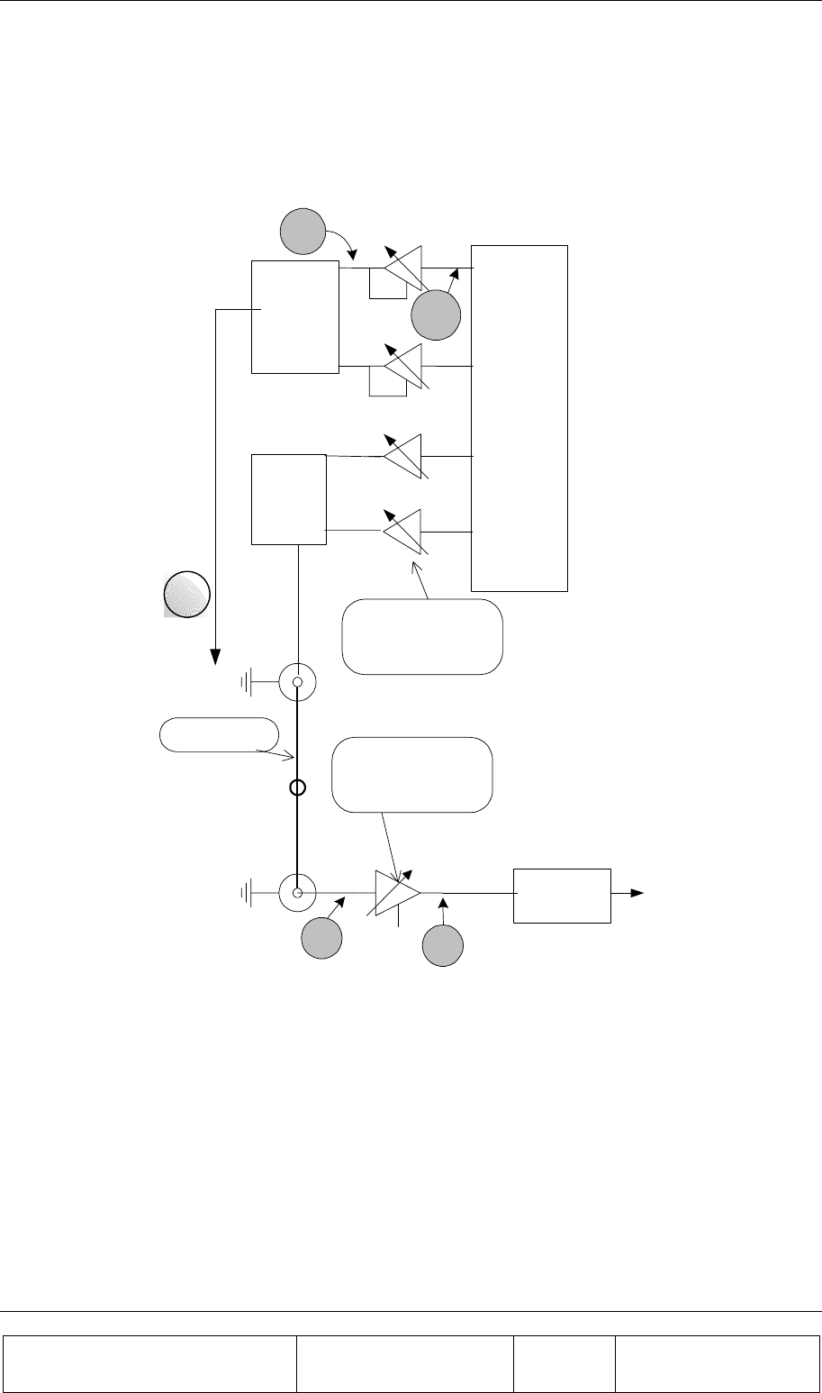
2.8.5. Calibrating the Transmit Channel Gain
Before calibrating the transmit channel gain and connecting the BTS transmitter to the BEAMER -Tx
array input, verify that the Tx-ABT is set to minimum gain (maximum attenuation). Instructions for
Tx-ABT gain setting can be found in section 2.8.3. This is essential for protecting the BEAMER from
possible overdrive due to high input power from the BTS.
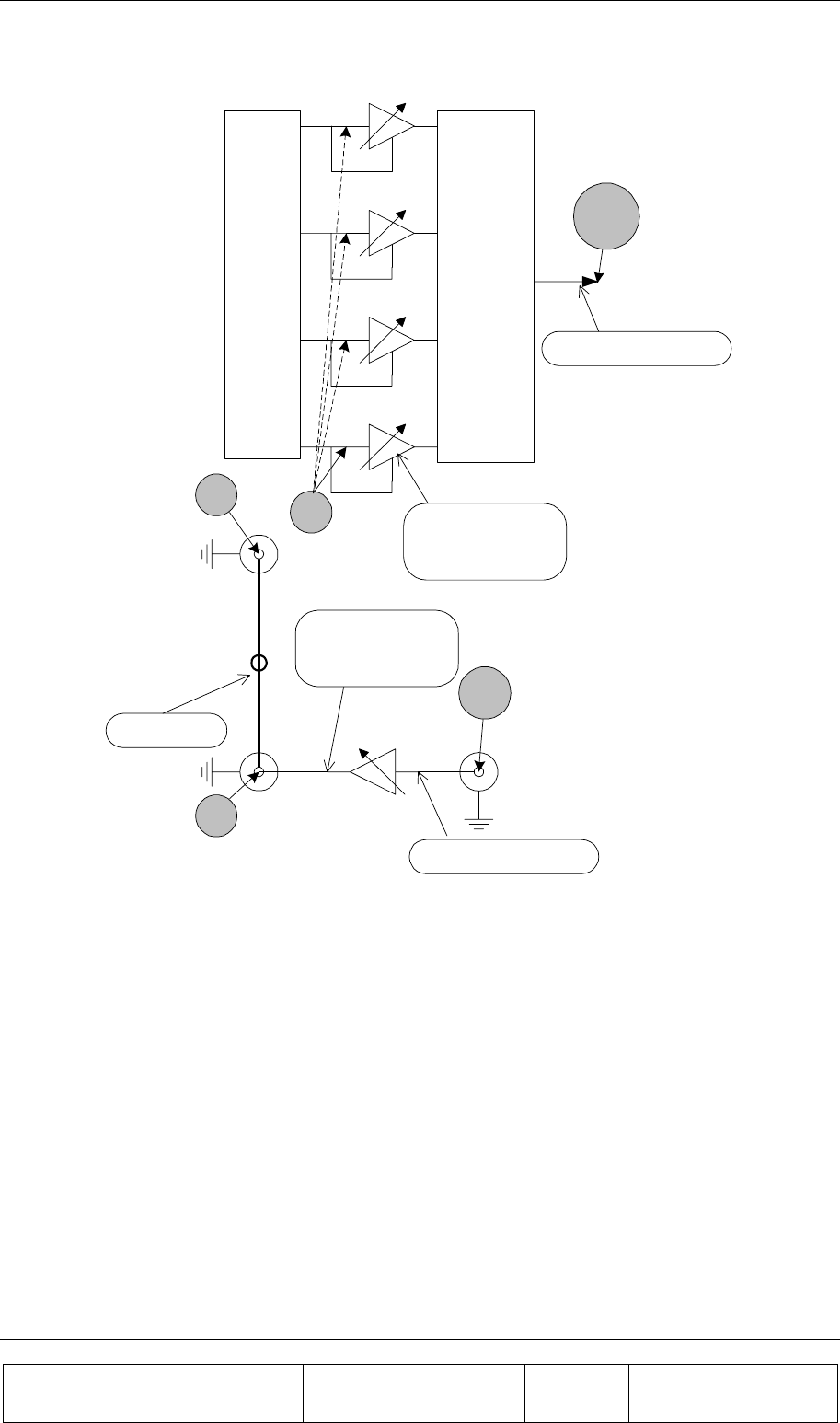
The following diagram can be used as a guideline to determine the gain distribution over the transmit
link. The numbers within the shaded circles represent typical BEAMER system expected
performance. However, some gain variations might occur. These variations might be due to gain
variations with BTS output power, the active Bias-T gain, RF cable loss and BEAMER -Tx gain. It is
therefore important that the gain calibration procedure will be performed whenever one of the system
components is changed: the BEAMER array, the RF cable, the active Bias-T or the BTS up-converter
output.
INSTALLATION GUIDE
Proprietary Information
Title: BEAMER Array System
Assembly and Operation Manual
Doc. No.: 913000100 Rev.: 00 Page: 50 of 92
Beamer
Array
[G=13.5dBi]
G
1:4
Divider
Loss=L
G
ABT
BTS
Input
P
in
Pout (max)=10dBm
G=30±1dB
GC=0 to15.5dB
L=0 to
6dB
Pout(max)=33dBm
G=37±0.5dB
GC=0 to
EIRP=52.5dBm(max)
Combined
in the Air
Beamer 4
G
G
Beamer 3
G
Beamer 2
Beamer1
-20
dbm
Pin=-5dBm to -20dBm
+8
dbm
Coax
15.5dB
+39dbm
[L=6db]
+2
dbm
-4
dbm
Figure 21: Tx link budget example
2.8.5.1. Estimating the Required Tx-ABT Gain
The purpose of this procedure is to verify that the BEAMER system available gain is sufficient to
cover the expected RF losses, before starting the actual Tx calibration.

INSTALLATION GUIDE
Proprietary Information
Title: BEAMER Array System-
Assembly and Operation Manual
Doc. No.: 913000100 Rev.: 00 Page: 51 of 92
Measure or estimate, according to the RF cable's vendor specifications, the RF losses over the Tx RF
cable. Typical loss for ½" cable is 0.11db/meter or about 5.5dB/50meters. (LTX-CABLE)
Measure or estimate the output power from the BTS up-converter at full capacity (PBTS)
Using G BEAMER (min)=36dB, estimate the needed output from the Tx-ABT:
Pout(ABT)=33dBm-G BEAMER +6dB+0.5dB+ LTX-CABLE
Verify that Pout(ABT)<+10dBm. If the computed Pout(ABT) is higher than the required limit, you
should use lower loss RF cable.
Estimate the Tx-ABT gain to achieve the required ABT output:
G
ABT = Pout(ABT)-PBTS
The maximum available GABT is 30dB, reducible to 14.5dB in steps of 0.5dB.
2.8.5.2. Setting the Actual Tx-ABT Gain
The following procedure will set the actual ABT-Tx gain to achieve the required output power from
the BEAMER array (+33dBm per BEAMER module, +39dBm or 8Watts at the antenna port).
1. Using the PC or BTS interface, verify that the Tx ABT gain is set to minimum.
2. Connect the BTS up-converter output to the Tx-ABT input.
3. Set the BTS up-converter to full capacity, single carrier simulated CDMA output (if this feature is
not available from the BTS, use a commercial CDMA source, such as HP4431B - ESGD, to generate
the required signal. Note that the BEAMER power measurements are calibrated for CDMA RF
signals only).
4. Read the BEAMER power indications for each BEAMER module connected to the array. Issuing
the command read BEAMER indications (code 132), with the appropriate ICU and BEAMER
addresses does this. Output power indication is given within a range of 0-14dB above +20dBm.
5. Repeat for all four BEAMER -Tx modules integrated into the array. Compute the average output
power:
∑
=
=
4
1
4
1
i
iAV PP
Where Pi is the measure output power from BEAMER -Tx #i, as indicated by read BEAMER
indications command.
6. Watch for variation between the Pi readings. The differences between the BEAMER -Tx measured
output power, for output power in the range of 26dBm<Pi<34dBm should not differ in more than
±2dB.
7. If Pav is less than 24dBm, increase the ABT-Tx gain by 5dB. Otherwise, increase the Tx-ABT gain
by 2dB.
8. Repeat steps 4 to 8 until Pav~31dBm
9. Increase the Tx-ABT gain in 0.5dB steps until Pav=33dBm±0.5dB. Verify, at this position, that
between units variation of BEAMER -Tx reading is less than ±2dB.
10. Record the calibrated Tx-ABT setting and the BEAMER -Tx readings in the BEAMER system
installation record sheet.
INSTALLATION GUIDE
Proprietary Information
Title: BEAMER Array System
Assembly and Operation Manual
Doc. No.: 913000100 Rev.: 00 Page: 52 of 92
2.8.6. Calibrating the Receive Channel Gain
The Pol. BEAMER Rx array gain distribution is illustrated in the following figure. It is assumed that
the RF cable loss is 6dB. The shaded circles represent the received system noise level, at maximum
available gain and at 1.25MHz bandwidth.
Beamer
Array
[G=13.5dBi]
2:1
Rear
Combiner
[L=0.3dB]
RF Coax
Loss=L
G
ABT
BTS
G=6±1dB
GC=0 to 15.5dB
L=3 to 8dB
G=30±1dB
GC=0 to 15.5dB
2:1
Rear
[L=0.3dB]
BTS down
Converter
RX
2RX
1
Noise P
in
Input
-82
dbm
-88
dbm
Noise Figure=4db
Combiner
-82
dbm
-112
dbm
Beamer
-82
dbm
Figure 22: Rx channel gain distribution example
The main factors to consider, when calibrating the Rx channels are as follows:
The total system gain should be high enough to assure that the system input noise level will be driven
beyond the down-converter output AGC nominal bias point, when the BEAMER plus BTS down
converter gain is at the maximum available gain.
The total BEAMER system gain should not be too high, to avoid excessive reduction of the system
IIP3 thus increasing the system susceptibility to interference. As a rule of thumb, an excess gain of 6-
10dB beyond the minimum required gain from rule 1 is the maximum required gain for rule 2.
For efficient diversity operation, even at relatively low signal to noise ratio, the two Rx channels gains
should be balanced to ±2dB.

INSTALLATION GUIDE
Proprietary Information
Title: BEAMER Array System-
Assembly and Operation Manual
Doc. No.: 913000100 Rev.: 00 Page: 53 of 92
The BEAMER -Rx programming property offers the system integrator the tool for calibrating the
system gain, in full accordance with the above rules.
The proper trade-off between these rules should be found. As an example, if the two Rx channel are
very much unbalanced an excessive gain increase might be required at one channel, causing possible
interference susceptibility on that channel.
Since it is impossible to accurately calibrate the BEAMER system reverse link gain without removing
the antenna element (thus, effectively disassembling the array) the gain balance will be calibrated
using an external low power CW transmitter located at short range (50-100meters) away from the
array, transmitting at vertical polarization.
2.8.6.1. Estimating the Required Rx-ABT and BEAMER Rx Gain
The purpose of this procedure is to verify that the BEAMER system available gain is sufficient to
cover the expected RF losses, before starting the actual Rx calibration.
1. Measure or estimate, according to the RF cable's vendor specifications, the RF losses over the Rx
RF cable. Typical loss for ½" cable is 0.11db/meter or about 5.5dB/50meters. (LRX-CABLE)
2. Measure or estimate the minimum input power to the BTS down-converter required for the AGC
bias point at maximum BTS down-converter gain (PBTS)
3. Using G BEAMER =25dB, estimate the needed gain from the Rx-ABT:
G(Rx-ABT)=PBTS-(-120dBm+G BEAMER -0.5dB- LRX-CABLE)
4. If the estimated G(Rx-ABT) is higher than 6dB, increase G BEAMER to get (Rx-ABT)~6dB. The
maximum available BEAMER -Rx gain is 30dB. If this limit is reached, you should use a lower loss
RF cable.
5.If the estimated G(Rx-ABT) is lower than -3dB, reduce the Rx- BEAMER gain and increase the Rx-
ABT gain. To avoid affecting the system noise figure, do not reduce the Rx- BEAMER gain below
20dB.
6. Record the required G(Rx-ABT) and G BEAMER.
2.8.6.2. Calibrating the Actual Reverse Link Gain
Calibrating the Rx channels is straightforward, using the ABT-Rx programming feature. However,
testing the actual calibration is not immediate, since, unlike the Tx channel calibration, power level
monitoring is not available for the Rx channels.
Rx channel calibration is performed by measuring the received Rx channels RF level, using a
reference mobile CDMA transmitter, or by measuring the background noise level for each receiver
using the BTS built-in software and hardware level measurements aids. These procedures, although
not requiring special test equipment, do require some interaction within the BTS software and
hardware. We leave this procedure for the customer's engineering personnel. Celletra will provide the
customer the needed technical support for performing the tests.
Note, however, that both the ABT-Rx gain and the BEAMER -Rx gain are calibrated to ±1dB (a total
of ±2dB uncertainty). We can thus guaranty, with good confidence level, that the RF front-end gain is
balanced within ±2dB for both Rx channels.
1. Connect the BEAMER array to the ICU's ABTs, for both Rx channels.
2. Using a PC or the BTS controller software, set the Rx- BEAMER and both Rx-ABT gain to the
computed required gain.

INSTALLATION GUIDE
Proprietary Information
Title: BEAMER Array System
Assembly and Operation Manual
Doc. No.: 913000100 Rev.: 00 Page: 54 of 92
The receivers gain is set. You can perform gain tests, using one of the above-suggested procedures.
2.9. BEAMER System Sector Array Installation Record
Sector # ...............................................
ICU address.........................................
ICU ID number ................................... (from unit label)
Array Number .....................................
2.9.1. Installed BEAMER Modules
Unit#1 ID(from unit label).................. system address
Unit#2 ID (from unit label)................. system address
Unit#3 ID (from unit label)................. system address
Unit#4 ID (from unit label)................. system address
2.9.2. RF Cable Loss
Tx........................................................ dB
Rx1...................................................... dB
Rx2...................................................... dB
2.9.3. Tx Channel
BTS output power level ...................... dBm (at sector maximum capacity)
Tx-ABT gain....................................... dB
BEAMER measured output power:
P1 ........................................................ dBm
P2 ........................................................ dBm
P3 ........................................................ dBm
P4 ........................................................ dBm
Average............................................... dBm
2.9.4. Rx Channels
Estimated ABT-Rx gain
Rx1...................................................... dB
Rx2...................................................... dB
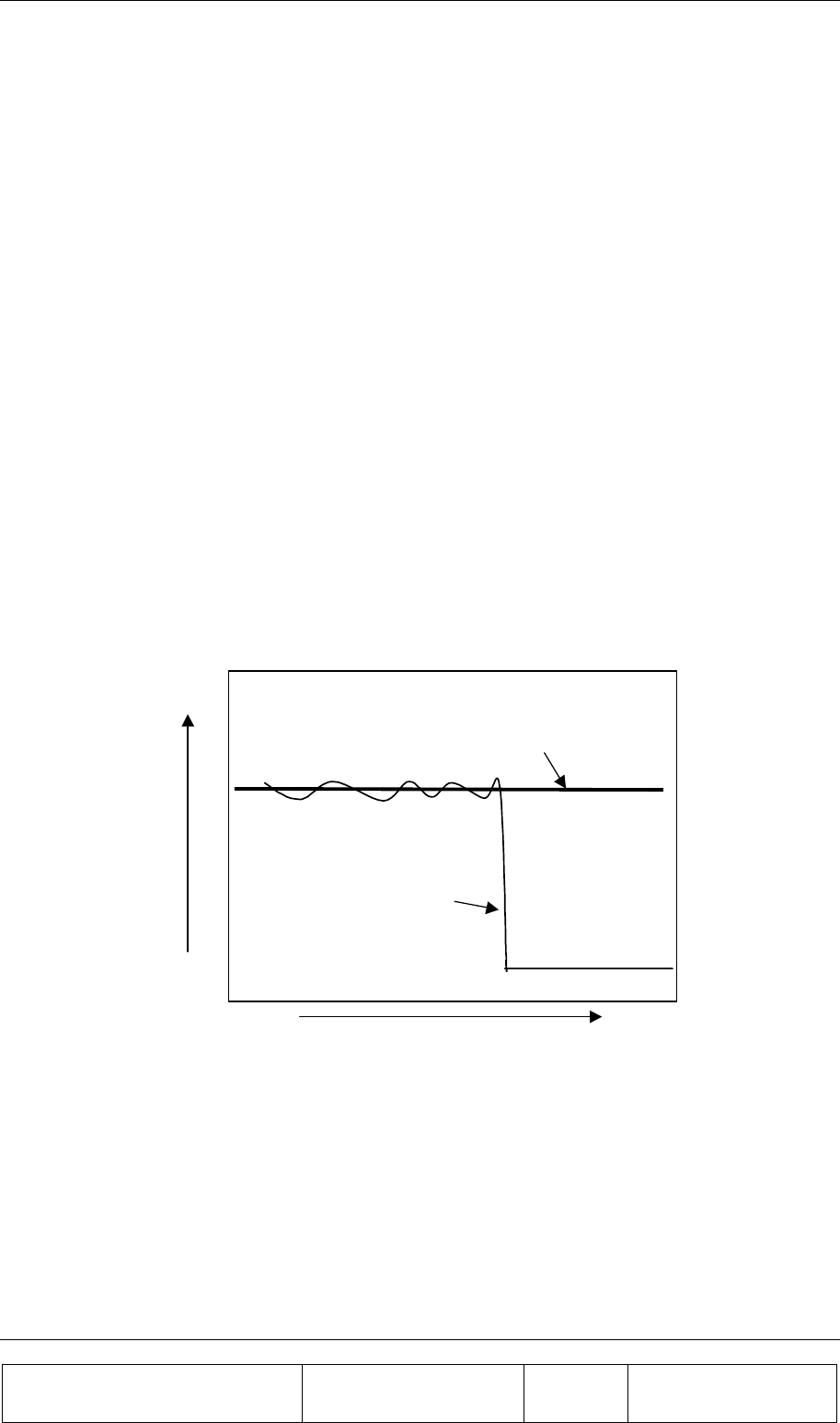
INSTALLATION GUIDE
Proprietary Information
Title: BEAMER Array System-
Assembly and Operation Manual
Doc. No.: 913000100 Rev.: 00 Page: 55 of 92
2.10. Test Procedure for Measuring the Rx Gain Balance
This section describes a way to measure the gain difference between to RF front-end channel.
Following the installation of a Pol. BEAMER array.
The measurement requires test equipment and somewhat involved test set-up, based on mobile RF
signal generator connected to an antenna, capable of rotating on the horizontal plane. This test setup is
not always available. Moreover, the good balance between the BEAMER gain blocks, on both the
BEAMER -Rx modules and the ICU, guarantees the gain balance.
However, we suggest to perform this measurement to one or two selected sites, as part of the system
validation tests.
1. Place a signal generator with an omni-directional antenna, at a distance of 50-100meters from
the array. The antenna should be mounted as a vertically polarized antenna.
2. Tune the signal generator output to Rx Center frequency, output power of 0dBm.
3. Connect a spectrum analyzer to the ICU's Rx-ABT output for Rx1 channel. Tune the spectrum
analyzer to Rx Center frequency, zero span, RBW=30kHz, reference level =-20dBm@5dB/div,
sweep time = 10Seconds.
4. While constantly moving the transmitting antenna on the horizontal plane, without altering the
polarization direction, watch the spectrum analyzer display of the received CW carrier. (you
can use a rotating plate or move the antenna manually).The spectrum analyzer display will
show a varying level line, around ~-30dBm. Estimate the average level of this line, Pr1, to
±1dBm.
Time
Power
Estimated average level
Recorded trace
Figure 23:Measuring the received
1. Repeat for the other Rx-ABT output, for Rx2 receiver, to get Pr2.
2. The readings for Pr1 and Pr2 should match to ±2dB. You can compensate up to ±4dB by fine-
tuning the Rx-ABT gain (available gain step is 0.5dB). It is recommended to increase the gain
of one Rx-ABT and to reduce the gain of the other, to minimize the effects of possible over- or
under-gain conditions. If Pr1 and Pr2 differ within more than ±5dB, it might indicate an
installation problem.

INSTALLATION GUIDE
Proprietary Information
Title: BEAMER Array System
Assembly and Operation Manual
Doc. No.: 913000100 Rev.: 00 Page: 56 of 92
2.11. Smart-Terminal Program Description
This program can be used for communication protocol debugging and testing. It is written in Visual
Basic for Windows 95 environment and provides basic control on the ICU and BEAMER parameters,
via the RS485 or RS232 serial communication ports.
The program is primarily oriented for engineering debugging and it is not intended to be used as a
commercial interface to the ICU. For this purpose, Celletra has developed the more powerful and user
friendly BSM program. However this program is not needed for ICU operation, since it is operated
with the MBTS controller supervision.
Note that when interfacing the ICU with RS485 interface to a PC, an appropriate hardware converter
should be used for the RS485.
In the following description the following notations are used:
• Bold italic characters, i.e., System Setup - represent drop down menu.
• Bold characters, i.e., Send - represent a 'radio' button or on screen displayed data.
• Quoted italic characters, i.e., ‘Commands’ - represent a directory or a file name.
2.11.1. Program Installation
The program is installed with the setup.exe file. The program was tested on Windows 95/98 machine,
environment. Other known problem is that the file "TDoubleRangeValidator.ocx" will not install
correctly. This file should be installed in Windows/System directory. It was found that sometimes it
will not be installed or the installed file will not be recognized. If this happens, it is recommended to
install the file manually, using the attached updated "TDoubleRangeValidator.ocx" file. Just copy the
file to the Windows/System directory.
The program will be installed under 'C:/Program Files/Smart Terminal2'. After the installation, copy
the attached 'Commands' directory to 'C:/Program Files/Smart Terminal2/Commands' directory. This
directory contains the command scripts for the ICU to PC communication protocol (see below).
Following the installation, a shortcut named 'Smart terminal2' will be created in the Start/Programs
menu.
2.11.2. Running the Program
Run the program by clicking the 'Smart terminal2' shortcut on the start/programs menu. The
program has one drop-down menu item available: System Setup. Pressing the system-setup
tab will reveal three menu items: Com Port, Get File and Save File.
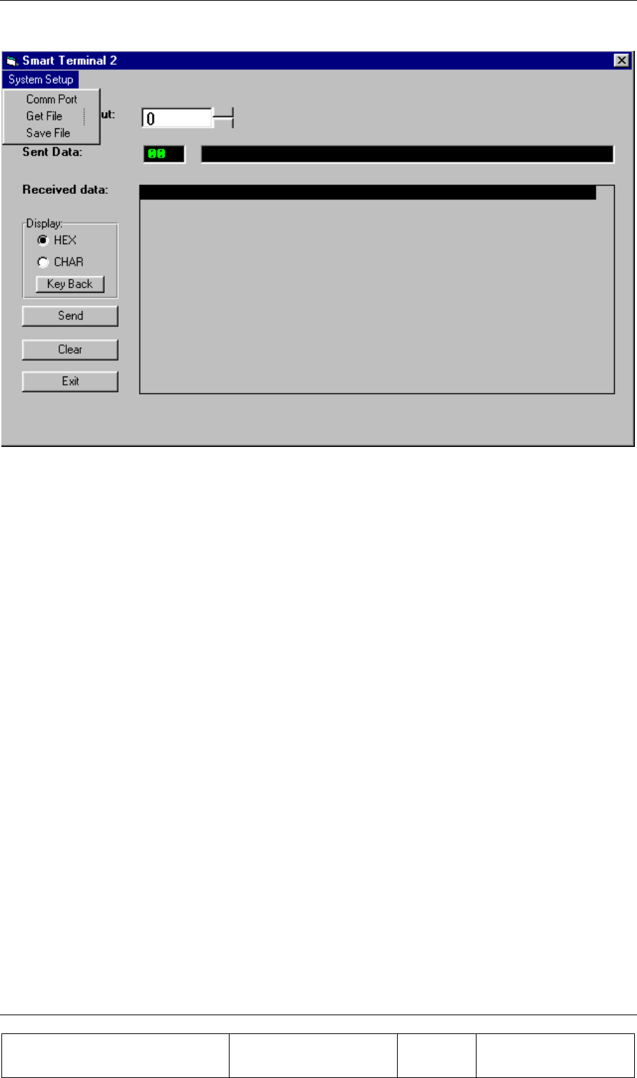
INSTALLATION GUIDE
Proprietary Information
Title: BEAMER Array System-
Assembly and Operation Manual
Doc. No.: 913000100 Rev.: 00 Page: 57 of 92
Figure 24: Smart Terminal 2 window
Com port - when pressing this tab the program displays the available serial ports. Select the one that is
connected via the RS232 interface to the ICU.
Get file - the program is loading commands to the ICU, written in the format as defined by the PC to
ICU protocol. These commands are stored in directory 'Commands' within the 'smart-terminal2'
directory. The commands are in ASCII format, one byte per line, each byte followed by carriage
return. A command file has *.bcd extension. These files can be edited and modified, according to the
PC to ICU protocol. When pressing the get-file tab, the smart terminal program will search the
'commands' directory and a list of the available commands will appear. The listing contains the
Windows file name, as it appears in the 'Commands' directory. It is thus suggested to name the files
with an appropriate name, making it easier to search for the needed command. A sample collection of
commands is attached to this package.
Save file - a command, entered either manually or as a script from the Commands scripts can be saved
into the Commands scripts directory using this tab.
The program screen also shows two windows (green characters on black background). The upper
window has one line. It contains the data that will be sent to the ICU (Sent Data). Every time the Send
button is pressed the data from this line is sent via the serial port to the ICU. The lower window is the
I/O response window (Received Data). It shows all the RS232 (or RS485) communication between
the PC and the ICU. Note that this window scrolls down (the most recent data is always at the top of
the window).
The displayed format can be changed from Hex to CHAR format. However, the input format should
always be decimal.
The Clear button clears the contents of the Received Data window.
The Exit button closes the program. Note that the program window cannot be minimized.
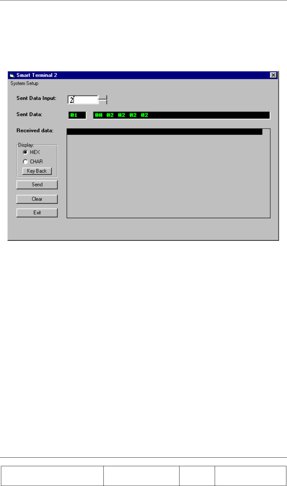
INSTALLATION GUIDE
Proprietary Information
Title: BEAMER Array System
Assembly and Operation Manual
Doc. No.: 913000100 Rev.: 00 Page: 58 of 92
2.11.3. Entering and Editing a Command
A command may be entered manually, entering byte value (0 to 255) decimal number at the Sent Data
Input window, followed by pressing the Send tab. The same command can also be sent with a script
file, using the Get File tab.
Figure 25: Entering and editing a command
2.11.3.1. Editing a Command
To edit a command, enter a value at the Sent Data Input window, followed by Send. If you make a
mistake or wish to correct an existing entry, use the Key Back to clear the entry, byte by byte, until
you have reached the wanted result.
Note that every time Send is pressed, the data at the Sent Data window will be sent to the ICU. This
does not affect the ICU performance - some of the incomplete commands will be ignored, some will
be executed - however, the last complete command will do the required job.
2.11.3.2. Entering a Script Command
When pressing the Get File menu, the programs look for *.bcd files at ./Commands directory. These
files should be stored line by line, in Hex format. The program will display the available scripts at the
Commands directory. Select the script name you wish to send, than press OK.
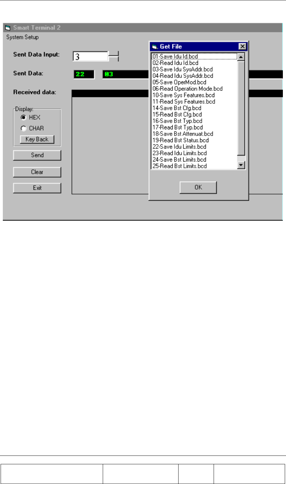
INSTALLATION GUIDE
Proprietary Information
Title: BEAMER Array System-
Assembly and Operation Manual
Doc. No.: 913000100 Rev.: 00 Page: 59 of 92
Figure 26: Using scripts
The script data will appear at the Sent Data window (command code followed by command data). The
program will not test for correctness of the script data. It assumes that the script is legal, and the data
is in Hex format.

Proprietary Information
Title: BEAMER Array System-
Assembly and Operation Manual
Doc. No.: 913000000 Rev.: 00 Page: 61 of 92
3. BSM (BEAMER SYSTEM MANAGER)
PROGRAM
3.1. Functions
The BSM program enables monitoring and control of the BEAMER units form a local or remote PC
based host computer.
Its main functions are:
Status report for each Array
Status report for each BEAMER
Control of system capacity and configuration
Control of each BEAMER
Monitoring & Control of the ICU functions and Active Bias-Ts
Setting the Active Bias-T amplifiers gains for Tx and Rx channels.
3.2. Requirements for Operation
3.2.1. Hardware
A PentiumTM based PC and a serial port on the PC
3.2.2. Software
Window 95/98/NT operating system

BSM (BEAMER SYSTEM MANAGER) PROGRAM
Proprietary Information
Title: BEAMER Array System
Assembly and Operation Manual
Doc. No.: 913000100 Rev.: 00 Page: 62 of 92
3.3. User Interface Description
3.3.1. Main Menu - Active Radiating Module System Manager
The Active Radiating system manager enables:
Display of systems status report such as:
Site name
Status of each Array
Real time date and clock
Authorized level for changes
Access to the following operating menus and functions:
System
Password
BEAMER monitoring and control
3.3.2. System Menu List
The SYSTEM menu list provides the functions to set system parameters. It consists of four menus:
Capacity, Configuration, Array Control and Com
3.3.2.1. Capacity Menu
The Capacity menu enables definition of the number of arrays in the system and maximum BEAMER
units per array
3.3.2.2. Configuration Menu
The Configuration menu enables:
Registration of new BEAMER units in the system..
Display the ID number of each BEAMER unit in the system.
Definition of the site name.
Definition of the conditions for failure messages.
Definition of the shutdown conditions for the Tx amplifiers.
Definition of status limits for failure messages (displayed by the ICU , the user
interface and sent to the AlBEAMER concentrating unit).
3.3.2.3. Comm Menu
The Comm menu enables selection of an available serial port
3.3.2.4. Array Control
The Array Control menu enables setting the gain for each Bias T in the system.
3.3.2.5. Password Menu List
The Password menu list enables entering the password to apply changes in system configuration.

BSM (BEAMER SYSTEM MANAGER) PROGRAM
Proprietary Information
Title: BEAMER Array System-
Assembly and Operation Manual
Doc. No.: 913000100 Rev.: 00 Page: 63 of 92
Four levels of password are available:
1. "Guest" level can only observe indications.
2. "Operator" level can apply changes to System configuration setting menu and BEAMER
setting menu in addition to "Guest" abilities.
3. "Supervisor" level can apply changes to the system settings, such as Capacity/Failure
conditions and Limit/Shutdown conditions, in addition to the "Operator" abilities.
4. "Administrator" can change the passwords in addition to "Supervisor" abilities.
3.4. Status Reports
3.4.1. Report by Visual Monitoring LEDs
Monitoring LEDs are located on the front panel of the ICU. Twelve green LEDs indicate that all
twelve arrays are functioning properly. Sixteen green LEDs indicate that all sixteen BEAMERs are
functioning properly A fatal failure of an array or BEAMER is indicated by a change in LED color to
Red. This same indication will be transferred to both the PC (or modem) and a dry contact. The
definition of a fatal array failure is software driven.
2 LEDs shows the Tx, Rx of serial port communications.
One LED shows the ICU condition.
One LED shows voltage condition.
3.4.2. Report by Sending Messages (Monitoring)
Either a PC or remote- connected PC can be used for Monitoring and Control of the BEAMER Array
System. The communication standard between the ICU and the local or remote PC is by a standard
RS-232/RS485 bus at a baud rate of 9.6 Kbps.
3.4.3. BEAMER Array System Control
Either a PC or remote- connected PC can be used for Control each individual BEAMER and each of
the BEAMER System. Local or remote PC can obtain control functions only
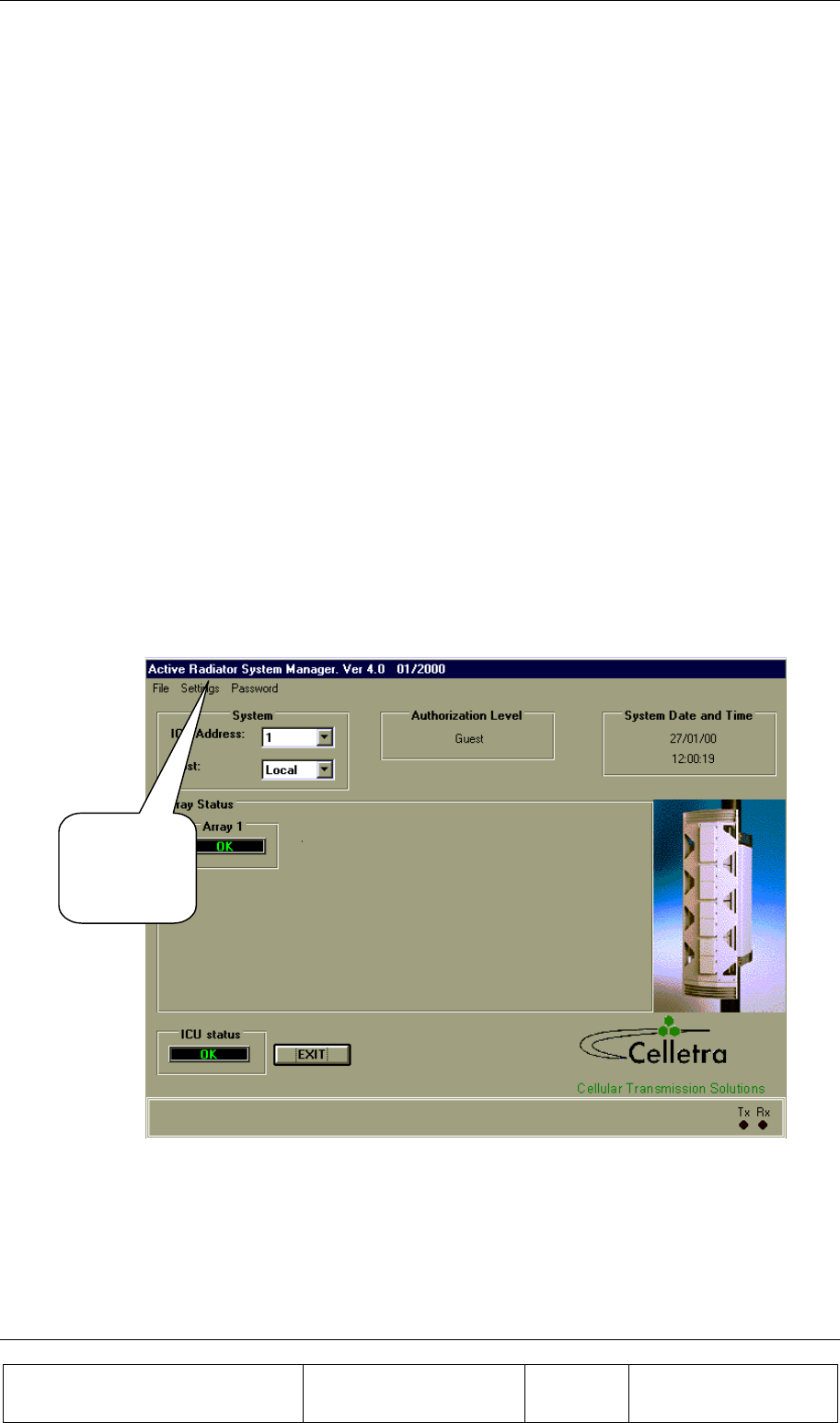
BSM (BEAMER SYSTEM MANAGER) PROGRAM
Proprietary Information
Title: BEAMER Array System
Assembly and Operation Manual
Doc. No.: 913000100 Rev.: 00 Page: 64 of 92
3.5. BSM S/W
The BSM Software enables system configuration and monitoring functionality of each unit in the
system.
Operation of the software will be described in the following paragraphs.
3.5.1. S/W Installation
The software installation is from diskette that supplied by Celletra .
• Put disk no.1 in the floppy drive and run "Setup".
• Follow the instructions on the screen until completion of installation.
3.5.2. S/W Operation
From the "Program files" in the Windows operating system select the BEAMER icon and operate the
software.
Follow the next steps in order to establish a correct system installation.
3.6. BSM Main Screen
From the
Setting menu
select the
Comm port.
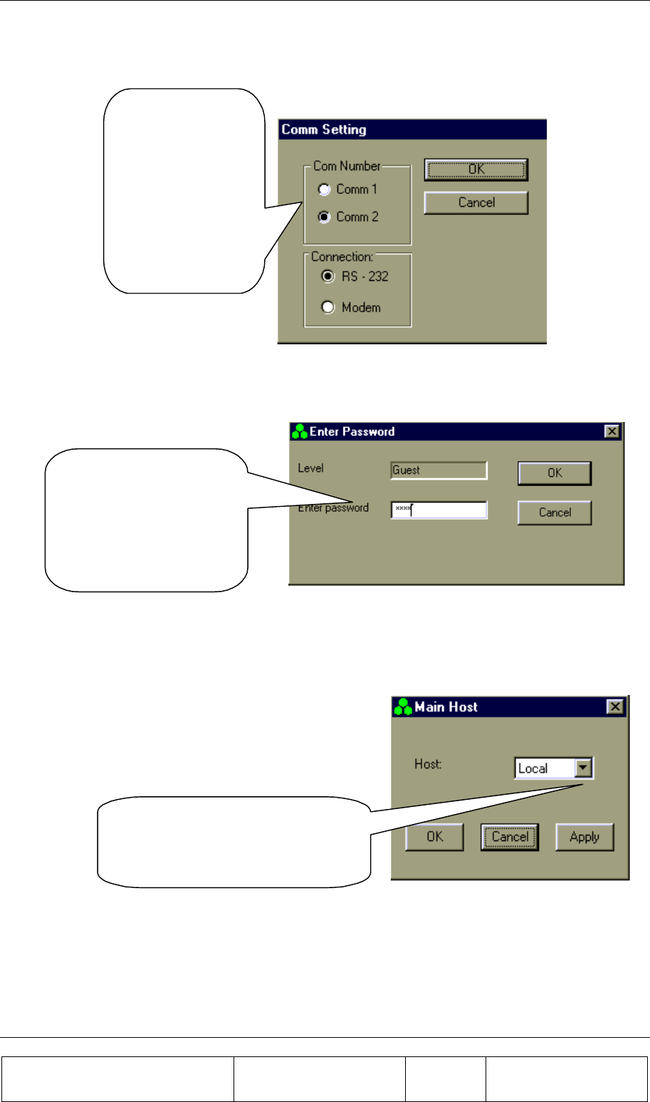
BSM (BEAMER SYSTEM MANAGER) PROGRAM
Proprietary Information
Title: BEAMER Array System-
Assembly and Operation Manual
Doc. No.: 913000100 Rev.: 00 Page: 65 of 92
3.7. Comm Port Selection
Connect RS-232
or RS-485 cable
to the ICU.
Run the cable to a
Comm port on
your PC.
3.8. Password Entering
In order to create or
modify a
configuration, you
will need
"Administrator”
password level.
3.9. Host Selection
From the Setting menu select
Main Host and then select either
Local or Remote Host.
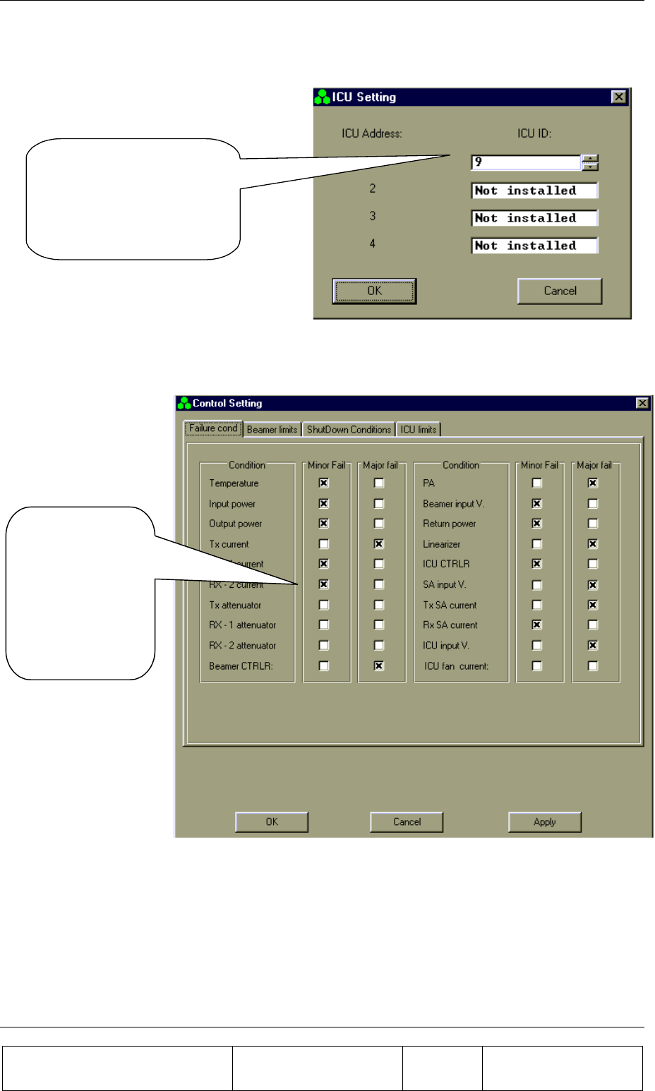
BSM (BEAMER SYSTEM MANAGER) PROGRAM
Proprietary Information
Title: BEAMER Array System
Assembly and Operation Manual
Doc. No.: 913000100 Rev.: 00 Page: 66 of 92
3.10. Installation of ICU in System
Operate ICU 24VDC Power
Supply .
Enter the ICU ID opposite
any one of the ICU
addresses.
3.11. Failure Conditions Selection
Select Major or
Minor Fail
according to
operator
application
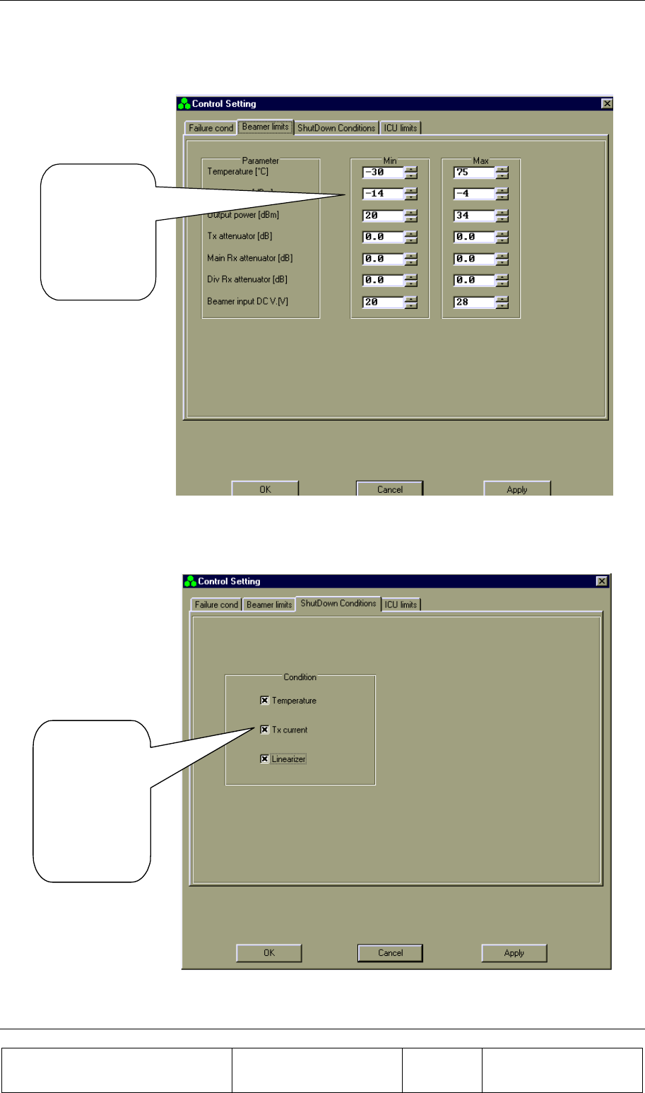
BSM (BEAMER SYSTEM MANAGER) PROGRAM
Proprietary Information
Title: BEAMER Array System-
Assembly and Operation Manual
Doc. No.: 913000100 Rev.: 00 Page: 67 of 92
3.12. BEAMER Limits Definition
Select limits
according to
operator
application
3.13. Shut Down Conditions Enable/Disable
Enable or
disable Shut
Down
conditions
according to
operator
aplication.
The “Shut Down Conditions” should be saved only after Beamer installation paragraph 4.18
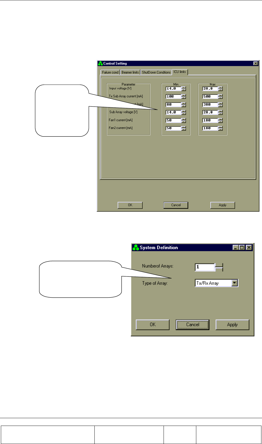
BSM (BEAMER SYSTEM MANAGER) PROGRAM
Proprietary Information
Title: BEAMER Array System
Assembly and Operation Manual
Doc. No.: 913000100 Rev.: 00 Page: 68 of 92
3.14. ICU Limits Definition
Select ICU limits
according to
operator
application
3.15. System Definition
Define the Number of
Arrays and the Type of
Arrays in your system.
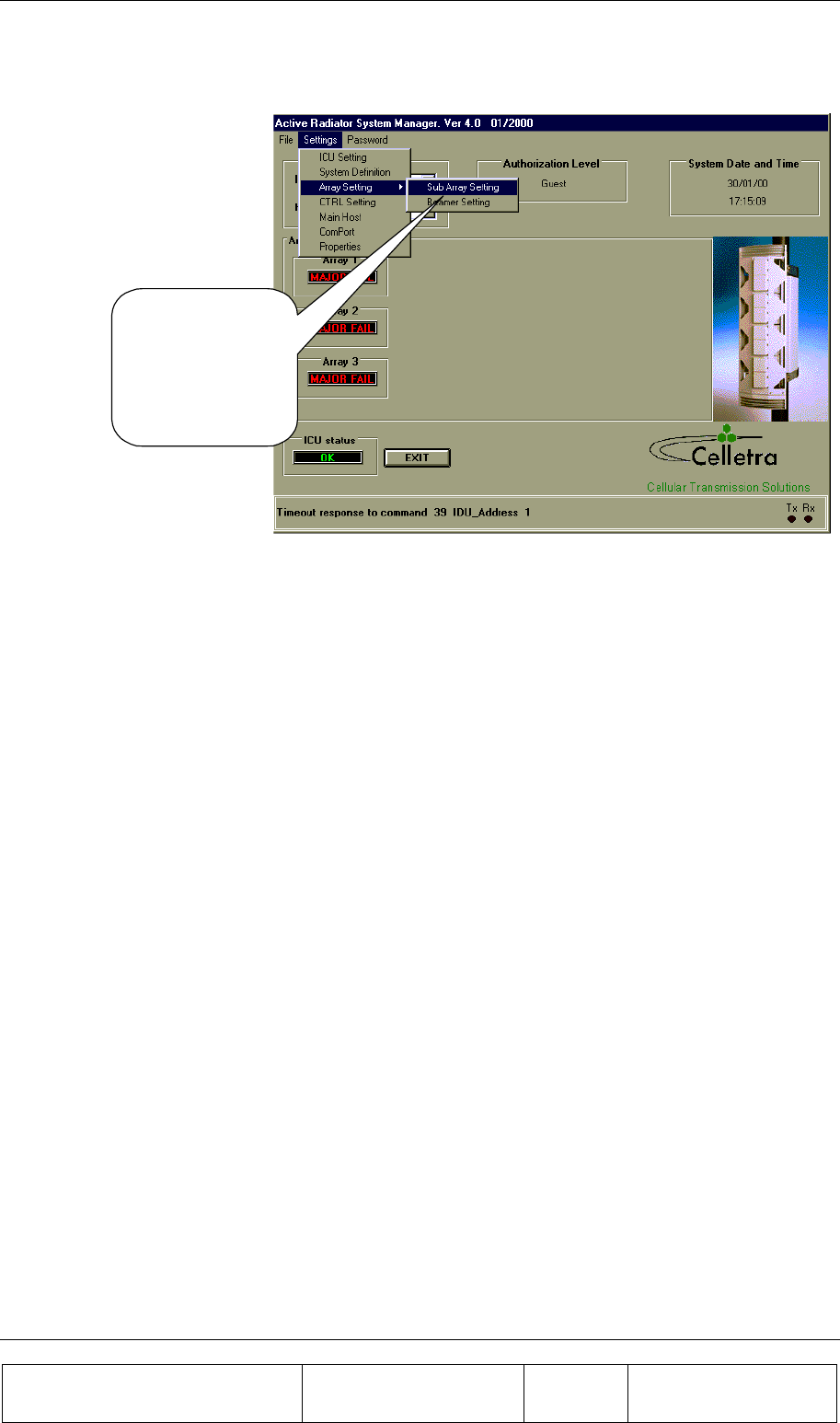
BSM (BEAMER SYSTEM MANAGER) PROGRAM
Proprietary Information
Title: BEAMER Array System-
Assembly and Operation Manual
Doc. No.: 913000100 Rev.: 00 Page: 69 of 92
3.16. Sub-Array and BEAMER Setting
From the Setting
menu select Array
Setting and
SubArray Setting.
(See instructions on
next page)
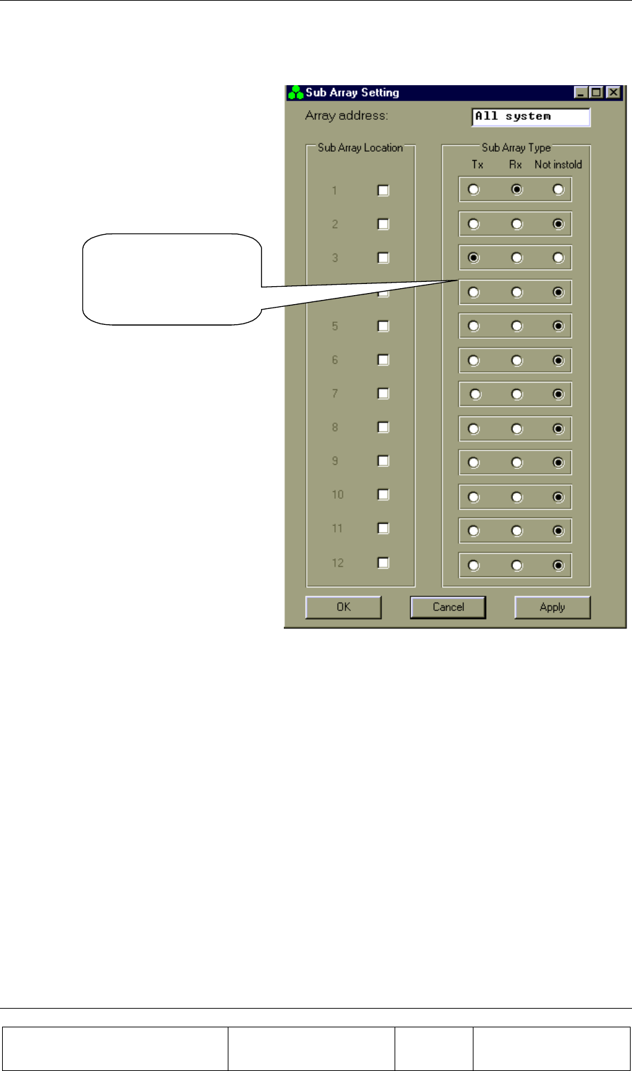
BSM (BEAMER SYSTEM MANAGER) PROGRAM
Proprietary Information
Title: BEAMER Array System
Assembly and Operation Manual
Doc. No.: 913000100 Rev.: 00 Page: 70 of 92
3.17. Sub Array Setting
Define Bias-Ts
according to system
definition and array
location
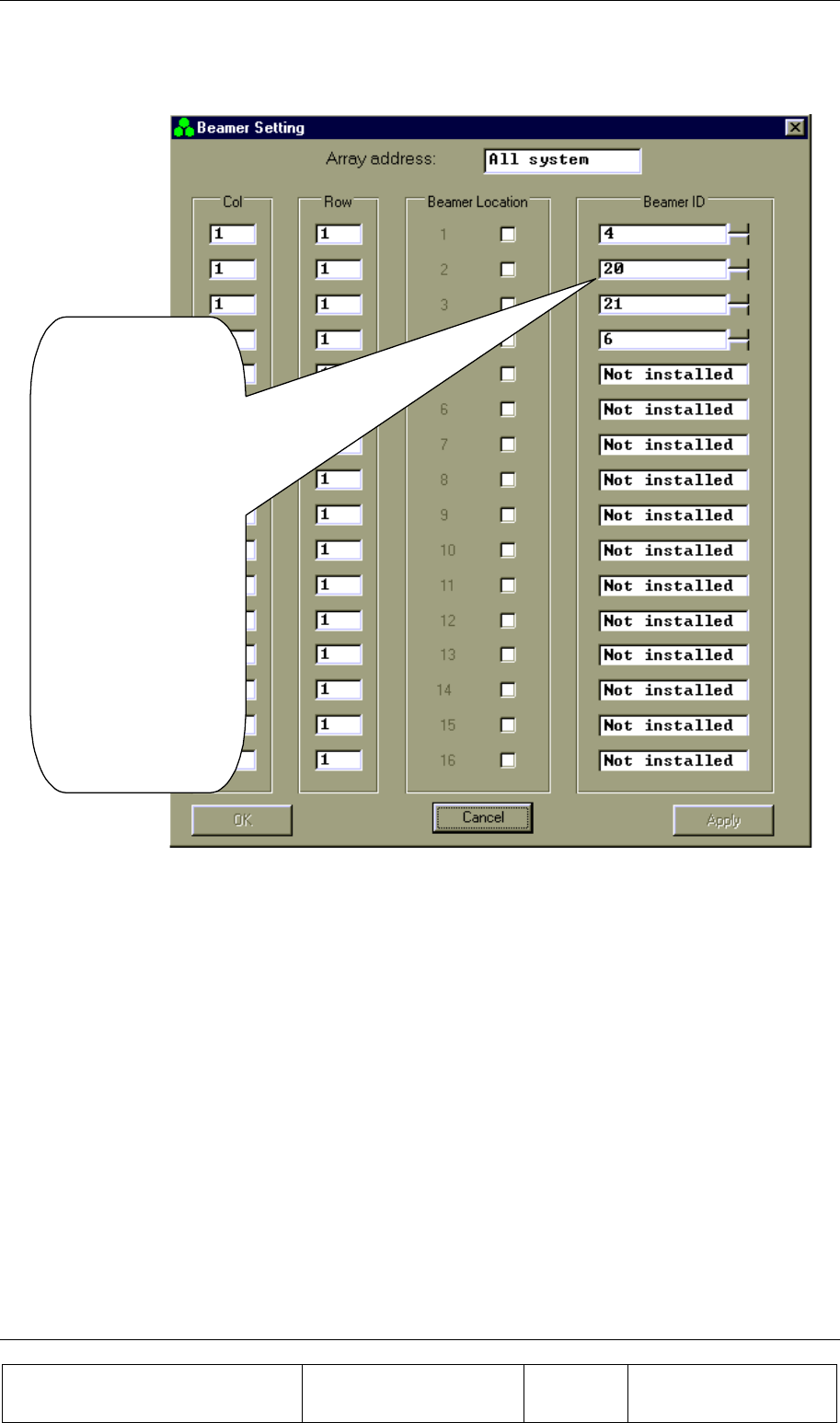
BSM (BEAMER SYSTEM MANAGER) PROGRAM
Proprietary Information
Title: BEAMER Array System-
Assembly and Operation Manual
Doc. No.: 913000100 Rev.: 00 Page: 71 of 92
3.18. BEAMER Installation
From BEAMER
Setting select
BEAMER.
The S/W starts
looking for installed
BEAMERs.
Wait until Apply
button becomes
available.
Add missing
BEAMERs or make
changes according to
existing installation
by adding BEAMER
ID numbers.
Confirm by clicking
Apply button.
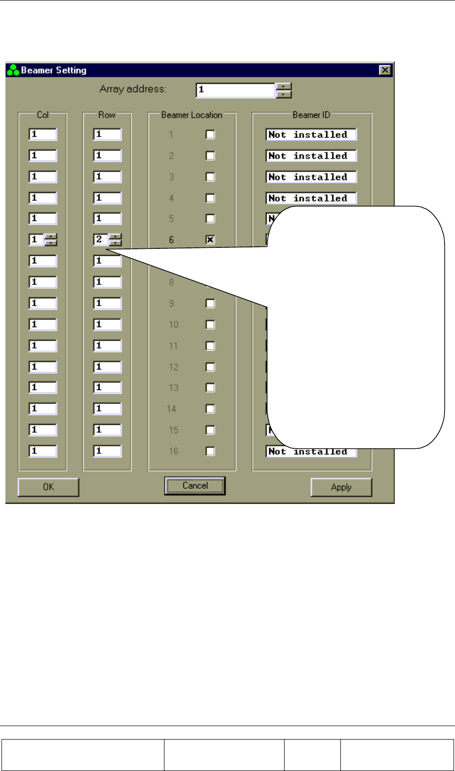
BSM (BEAMER SYSTEM MANAGER) PROGRAM
Proprietary Information
Title: BEAMER Array System
Assembly and Operation Manual
Doc. No.: 913000100 Rev.: 00 Page: 72 of 92
3.19. Column and Row Definition
In the Array address combo
box, select the Array number.
Check the Beamer Location.
Enter the Col and Row for the
Beamer.
Repeat for each Beamer in the
Array.
Click Apply when you have
completed an Array of
BEAMERs.
Repeat this procedure for all
the Arrays.
Click OK.
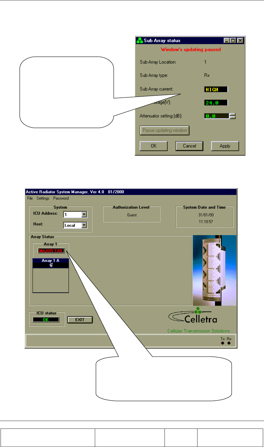
BSM (BEAMER SYSTEM MANAGER) PROGRAM
Proprietary Information
Title: BEAMER Array System-
Assembly and Operation Manual
Doc. No.: 913000100 Rev.: 00 Page: 73 of 92
3.20. Sub-Array Status and Attenuator Setting
Select from Array Status
window an Array and select
Sub-Array option.
Click Pause Updating Window
and adjust the attenuator value
between 0 and 15.5 dB.
Click Apply in order to save
your selection.
3.21. Control & BEAMER Setting
Point cursor at an Array window.
Click to view all BEAMER addresses in
selected Array.
Double click to see BEAMER Control screen.
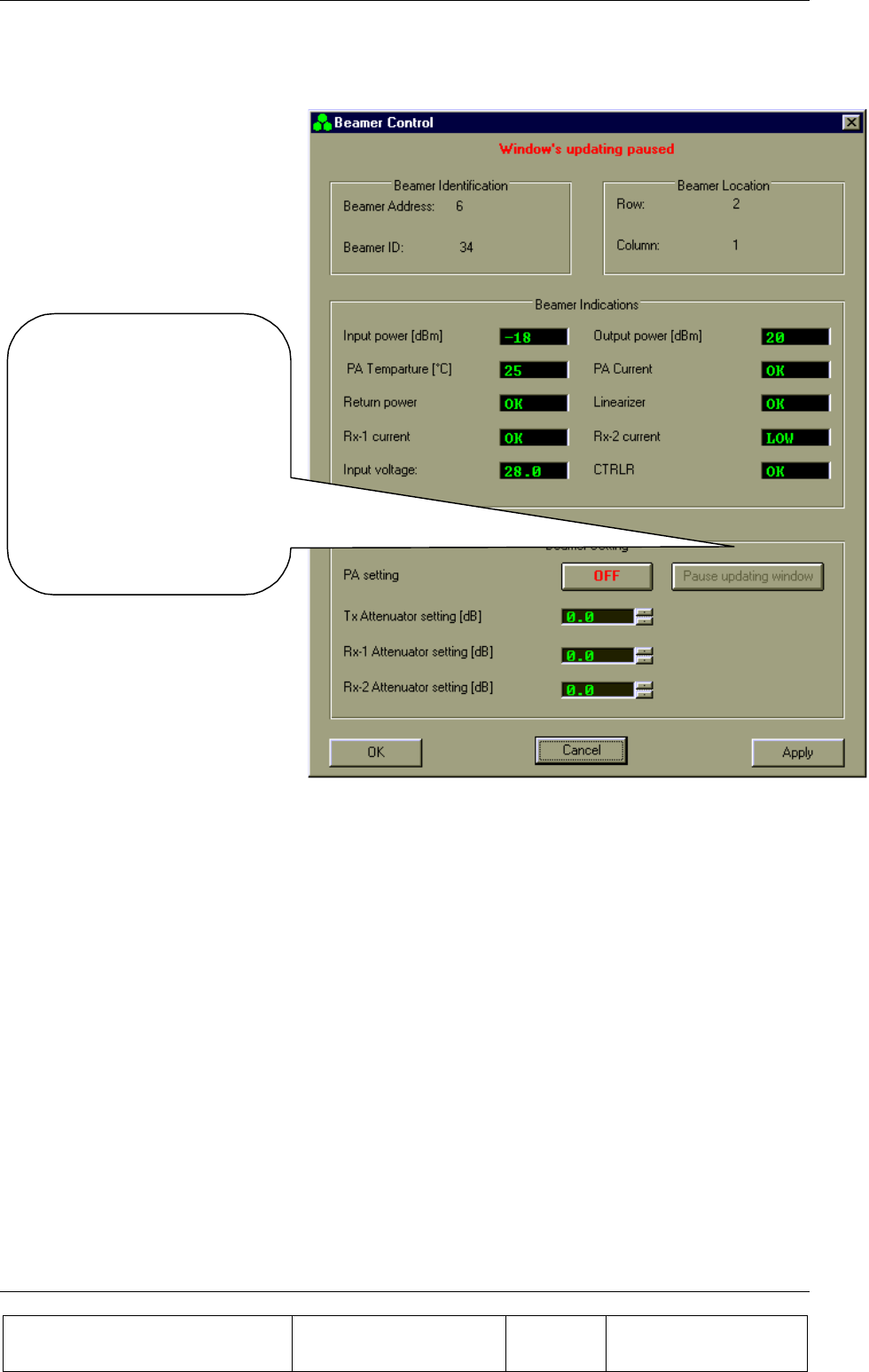
BSM (BEAMER SYSTEM MANAGER) PROGRAM
Proprietary Information
Title: BEAMER Array System
Assembly and Operation Manual
Doc. No.: 913000100 Rev.: 00 Page: 74 of 92
3.22. BEAMER Control
Click Pause Updating
Window and select
attenuator value for Tx and
Rx according to your
system definition.
Click Apply to save your
selection.
Click OK to return to Main
screen.
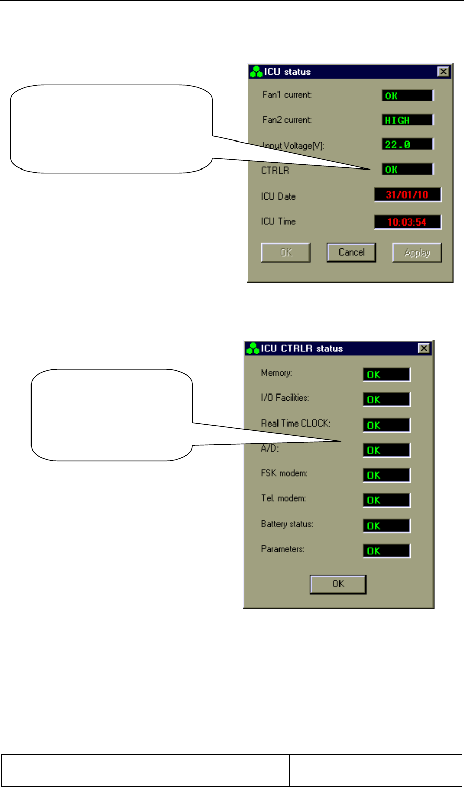
BSM (BEAMER SYSTEM MANAGER) PROGRAM
Proprietary Information
Title: BEAMER Array System-
Assembly and Operation Manual
Doc. No.: 913000100 Rev.: 00 Page: 75 of 92
3.23. ICU Status
Click on ICU window to see ICU
status.
In case of a failure, double click on
it to display details
3.24. ICU CTRLR Status
Double click on the
CTRLR window to view
this box, which shows the
CTRLR parameters in
detail.
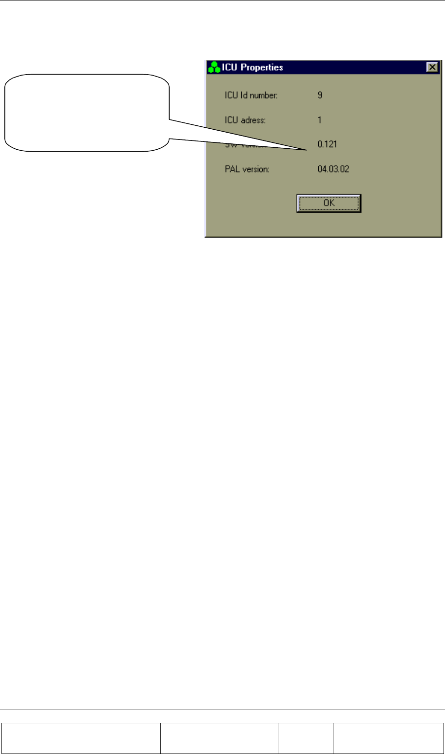
BSM (BEAMER SYSTEM MANAGER) PROGRAM
Proprietary Information
Title: BEAMER Array System
Assembly and Operation Manual
Doc. No.: 913000100 Rev.: 00 Page: 76 of 92
3.25. ICU Properties
From Setting you can select
ICU Properties to view the
SW versions of the ICU
CTRLR card

Proprietary Information
Title: BEAMER Array System-
Assembly and Operation Manual
Doc. No.: 913000000 Rev.: 00 Page: 77 of 92
4. SOFTWARE DOWNLOAD GUIDE
4.1. Introduction
This chapter is a guide to loading program files to the ICU and BEAMER via their Monitoring and
Control communication channels. This enables program upgrades in the field without dismantling the
equipment for that purpose.
The program loading is done from a PC with a using the CELLETRA SOFTWARE DOWNLOADING
SYSTEM program, which is supplied by CELLETRA.
This chapter describes the loading process to the ICU and the BEAMER using the CELLETRA
SOFTWARE DOWNLOADING SYSTEM.
4.2. Overview
4.2.1. Downloading Software to the ICU
In the software download process a new application program file is loaded to the ICU via the serial
communication channel and saved to the FLASH memory.
4.2.1.1. ICU Memory Configuration
The ICU controller includes two types of memories a FLASH memory and a RAM. The FLASH
memory includes the configuration parameters of the ICU (such as ID number, number of arrays,
failure conditions etc.) and the application program, which enables all the features of the ICU and
which is upgradable.
The RAM is used for logging events into the log file during regular operation of the ICU, and for
receiving the new application program for the ICU during the download process. A third memory is
located in the CPU component and includes the basic I/O program of the controller. This program
enables operation of the basic functions of the controller (such as serial communication and

SOFTWARE DOWNLOAD GUIDE
Proprietary Information
Title: BEAMER Array System
Assembly and Operation Manual
Doc. No.: 913000100 Rev.: 00 Page: 78 of 92
application program loading) and cannot be modified. The memory size allocated for the application
is 64 Kbytes. Programming a new application program into the FLASH memory does not affect the
ICU configuration parameters.
4.2.1.2. ICU Download Operation Mode
Loading a program file to the ICU is enabled while the ICU operates in Download mode. The
operation mode of the ICU is changed by a command through the serial communication channel.
When the ICU operates in Download mode, no operational function is performed. (That means that it
does not provide monitoring and control of the BEAMERs). The baud rate of the serial port increases
to 56 Kbaud. That enables faster transmission of data packets to the ICU during the download
process. The ICU returns to operational mode (Auto) at the end of the loading process or if there was
no data transmission from the PC within a predefined time period .
4.2.1.3. File Transmission From PC to ICU
4.2.1.3.1. File Transmission
The program file is a HEX type file and the data is ASCII format. While loading the file to the ICU
the PC sends the file content line by line. The ICU reports TO the PC about reception quality. If errors
were detected the transmission will be stopped and an error message will be displayed. The PC then
restarts the transmission. The program is contained in files of 64 Kbytes. That is, if the program size
is greater than 64 Kbytes it will be packed in two files that are distinguished by their names.
4.2.1.3.2. File Name Format
The file name has the following format: IDUxxTVVV.Hyy
IDU ICU application header
Xx Not relevant for loader
T Application type (0=Celletra/1=Korea)
VVV Application version
Hyyy HEX: The program is packed in one HEX file
H00 and H01: The program is packed in two HEX files
Example: IDUck0102.h01
IDUck: Software application
0: Celletra versionk
102: Software version number
h01: High package of the hex file

SOFTWARE DOWNLOAD GUIDE
Proprietary Information
Title: BEAMER Array System-
Assembly and Operation Manual
Doc. No.: 913000100 Rev.: 00 Page: 79 of 92
4.2.2. Downloading Software to the BEAMER
The Software download process enables loading of a new application program file for the BEAMER
host processor and the DSP via the serial communication channel and saving it to the FLASH memory
in the BEAMER.
4.2.2.1. BEAMER Memory Configuration
The BEAMER includes two processors a DSP and a HOST. The HOST processor is a general purpose
processor that is used for reporting BEAMER status to the ICU via a FSK channel and for
initialization of the DSP.
The BEAMER controller includes a FLASH memory that contains:
1. The configuration parameters of the BEAMER (such as ID number, calibration tables etc.).
These parameters are not affected during the loading process.
2. The application program that enables all the features of the BEAMER that can be replaced by
a new version.
3. The program and data files of the DSP that can be replaced by a new version.
The FLASH size contains two files of each program (two of HOST application, two program files for
the DSP, and two data files for the DSP). The required program files for operation are selected by the
user. The memory is arranged by pages (each page includes 128 bytes).
4.2.2.2. File transmission from PC to the BEAMER
4.2.2.2.1. File Transmission
The new file is transmitted page by page from the PC to the ICU and from the ICU to the BEAMER.
All files to be loaded are text files. The files contain a Header block, which is the properties block,
and the software to be loaded. When the load process is enabled, the baud rate of the of the serial port
(from PC to the ICU) increases to 56 Kbaud. That enables faster transmission of data packets to the
ICU during the download process. The ICU reports the PC about reception quality and if errors were
occurred the transmission will be stopped and an error message will be displayed.
The ICU sends the data packets received from the PC to the BEAMER and the BEAMER reports the
ICU about reception quality. If errors were detected the transmission will be stopped and an error
message will be displayed
4.2.2.2.2. File Name Format for HOST
Files will be identified by the following suffix: name.hst

SOFTWARE DOWNLOAD GUIDE
Proprietary Information
Title: BEAMER Array System
Assembly and Operation Manual
Doc. No.: 913000100 Rev.: 00 Page: 80 of 92
4.2.2.2.3. File Name Format for DSP
Files will be identified by the following suffixes:
• DSP Program file: name.dpm
• DSP Data file: name.ddm
4.3. User Interface for SW Download
4.3.1. Functions
The Software download program enables download program files to the ICU and the BEAMER from
a local PC-based host computer.
Its main functions are:
• Selection of the target for downloading (BEAMER or ICU)
• Selection of files to be loaded
• Transmission of files from the PC to the selected target (BEAMER or ICU).
• Monitoring of transmission process
4.3.2. Requirements for Operation
4.3.2.1. Hardware
• PentiumTM-based PC
• Free serial port from the PC
• At least 4 Mb free RAM
4.3.2.2. Software
Window 95/98/NT operating system
4.3.3. User Interface Installation
The software is installed from a diskette supplied by Celletra .
1. Put disk no.1 in the floppy drive and run "Setup".
2. Follow the instructions on the screen until completion of installation.
The program will be installed in the "Program files" subdirectory of the “Windows” directory.
4.3.4. User Interface Operation
The program can be operated from the program menu in the start menu. Another option is to create a
shortcut for the program from the "Program files" subdirectory in the Windows directory and operate
the program by clicking the icon
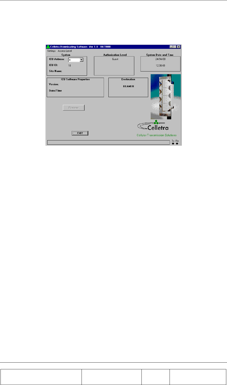
SOFTWARE DOWNLOAD GUIDE
Proprietary Information
Title: BEAMER Array System-
Assembly and Operation Manual
Doc. No.: 913000100 Rev.: 00 Page: 81 of 92
4.4. User Interface Description
When operating the program the following window will be displayed:
4.4.1. System Field
The System field displays the address of the ICU and its ID number that is controlled by the operated
program. In case that the system includes few ICUs the required ICU can be selected by its address
from the address bar.
When the program is operated it scans the addresses (1 to 4) and displays the address of the existing
ICUs in the System filed . In case that no ICU was connected or the ICU was not configured the
address bar will remain blank.
4.4.2. Authorization Field
Authorization field displays the actual authorization level. Two levels of authorization are available:
1. "Guest" level can only observe indications.
2. "Administrator" which enables the application of the loading process and change the passwords
in addition to "Supervisor" abilities.
4.4.3. System Date and Time Field
System date and time displays the PC’s actual date and time. That time will be registered as one of the
properties of the loaded file.
4.4.4. ICU SW Properties Field
ICU SW properties field is enabled when the loading process is enabled. It displays the properties of
the program file that exists in the ICU. The ICU property information includes the version number
and file loading date and time.
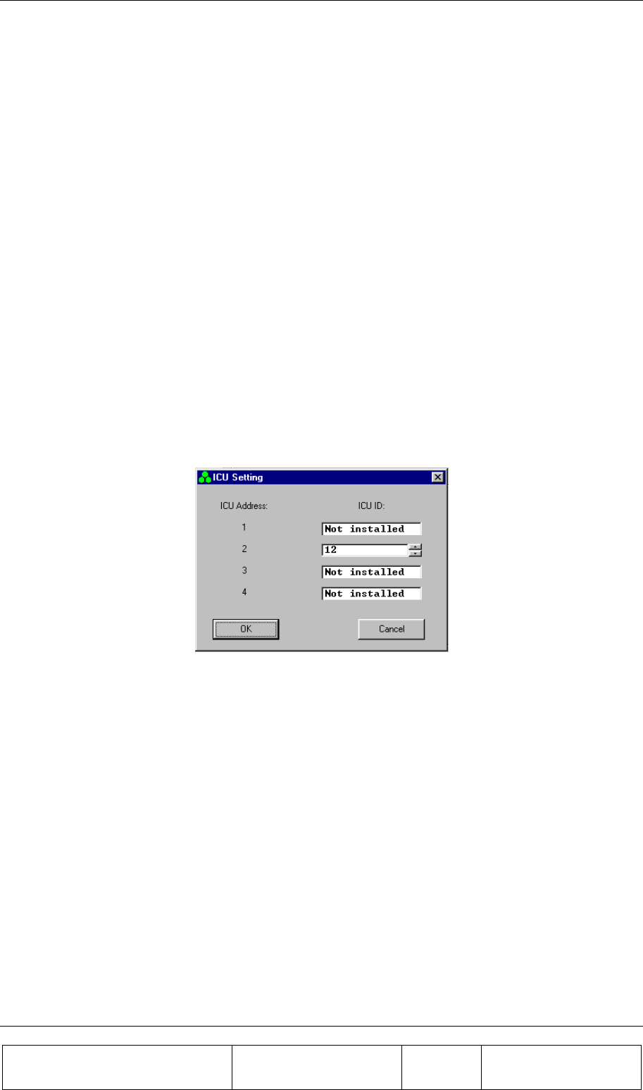
SOFTWARE DOWNLOAD GUIDE
Proprietary Information
Title: BEAMER Array System
Assembly and Operation Manual
Doc. No.: 913000100 Rev.: 00 Page: 82 of 92
4.4.5. Destination Field
Destination field displays the destination for the file loading – BEAMER or ICU.
4.4.6. Setting Menu
Setting menu includes the following functions:
• ICU Setting
• Software loading code
• Software remote loader
• Site name
• Destination
• ComPort
4.4.6.1. ICU Setting
If the connected ICU is not configured- meaning that it does not have an address - this function
enables defining and saving an address to the ICU. Click on ICU setting to display the following
window:
Setting ICU’s address is enabled by entering it’s ID number (which is known and is the ICU serial
number).
4.4.6.2. Software Loading Code
This function enables saving to the BEAMER details about present loading. Software loading code is
an alphanumeric expression up to 20 characters.
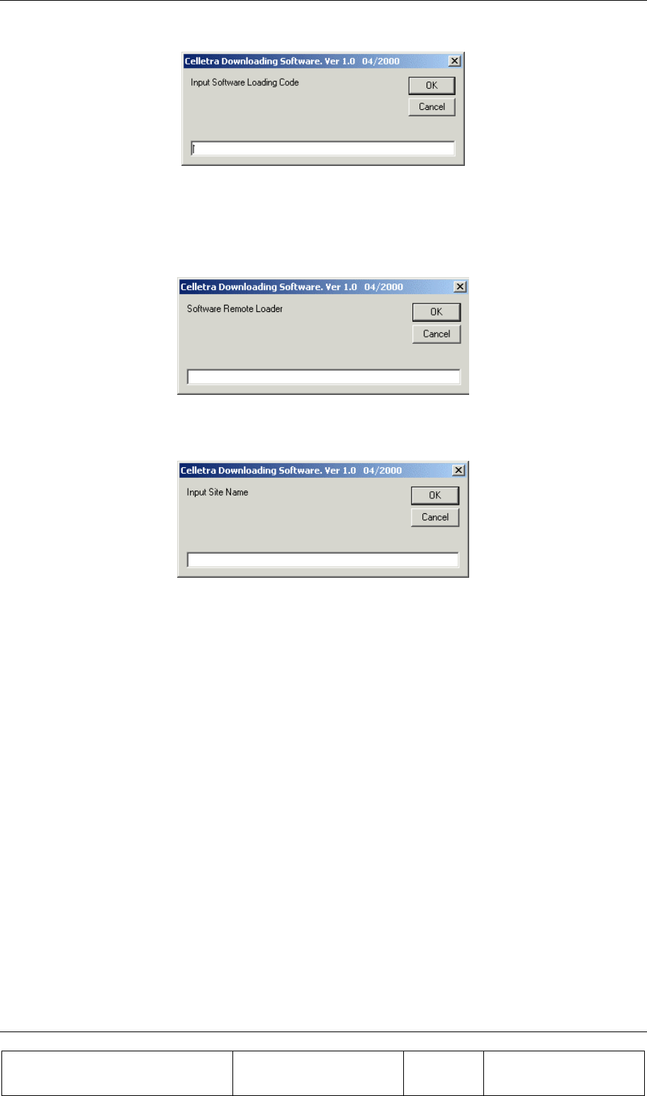
SOFTWARE DOWNLOAD GUIDE
Proprietary Information
Title: BEAMER Array System-
Assembly and Operation Manual
Doc. No.: 913000100 Rev.: 00 Page: 83 of 92
4.4.6.3. Software Remote Loader
This function enables saving of the program loader name into the BEAMER. Software remote loader
is an alphanumeric expression up to 20 characters.
4.4.6.4. Site Name
This function enables saving to the BEAMER the name of the site name where a program was
recently loaded to the BEAMER. Site name is an alphanumeric expression up to 20 characters.
4.4.6.5. Destination
This function enables selecting the required destination for the SW download: BEAMER or ICU
4.4.6.6. ComPort
This function enables selecting the required communication path from the PC to the ICU. Selection of
ComPort function will display the Comm setting window
Connecting the ICU is possible directly via RS232 interface for local connection or via telephone
modem for remote connection. The remote connection is enabled in ICU versions that include internal
telephone modem. The Comm setting window enables selecting the required path: RS-232 interface or
modem. It displays all the available serial ports in the PC and enables selecting a free port in the case
where the RS-232 interface is selected.
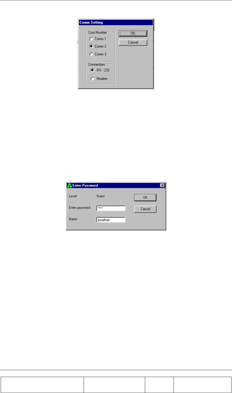
SOFTWARE DOWNLOAD GUIDE
Proprietary Information
Title: BEAMER Array System
Assembly and Operation Manual
Doc. No.: 913000100 Rev.: 00 Page: 84 of 92
4.4.7. Password Menu
Password menu enables the inclusion of the following functions:
1. Enter password and user name
2. Low level
3. Change the Administrator password
4.4.7.1. Enter Password
Clicking on the Enter password function will display the following window:
The displayed window enables entering the required password, which enables the loading process.
4.4.7.2. Low Level
Clicking on Low Level sets the Guest level authorization.
4.4.7.3. Change Password
This function is enabled when the Administrator authorization is enabled and enables changing the
password for authorization.
4.5. Program Loading Procedure
4.5.1. Procedure for Loading Program to the ICU
To load a new version of application program file to the ICU controller, follow the following
instructions:
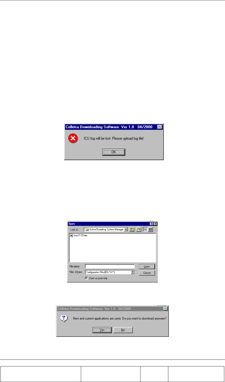
SOFTWARE DOWNLOAD GUIDE
Proprietary Information
Title: BEAMER Array System-
Assembly and Operation Manual
Doc. No.: 913000100 Rev.: 00 Page: 85 of 92
1. Connect the PC that includes the Celletra program loader program to the ICU via the serial
port.
2. If you wish to keep the log file then save it, otherwise the log file will be erased during the new
file loading.
3. Operate Celletra program loader program and wait until the address of the ICU appears at the
ICU address bar. If the system includes few ICUs, select the address of the required ICU from
the address bar.
4. From the Setting menu select Comport and select the required communication path to the ICU.
• If the PC is connected via the serial port of the PC then check the RS-232 and define the COMM
port in the PC that is used.
• If the PC is connected via the a telephone line by a modem, then check the MODEM and dial the
telephone number of the destination modem.
5. From the Setting menu, click on Destination and select ICU as the destination for loading. The
following warning message will appear to warn that the log file will be erased:
6. Exit to save the log file or Click O.K to continue. The properties of the existing file will be
displayed on ICU Software properties field.
7. Click on the Password menu then on Enter to enter the password that enables loading of a new
program. After you enter the correct password and your name the Start download command key
will be enabled.
8. Click the Start download command key to start the loading process. The following window will
be displayed:
9. Select the required file and click on the Open button. If the selected file is similar to the
existing (operational) file then following notice will be displayed:
10. If you wish to load the same file anyway then click Yes to continue, otherwise click No and
select other file.

SOFTWARE DOWNLOAD GUIDE
Proprietary Information
Title: BEAMER Array System
Assembly and Operation Manual
Doc. No.: 913000100 Rev.: 00 Page: 86 of 92
11. During the loading process a status bar will be displayed:
12. Wait about 3 minutes until the process is completed. If you wish to stop loading the file then
click on the Cancel button.
13. After the file has been loaded into the RAM successfully the ICU will program the FLASH
memory. During the FLASH programming the following message will be displayed:
14. The new program version will operate at the end of this process and the ICU is operational
again.
15. If the loading process has been failed the following warning message will be displayed:
4.6. Procedure for Loading Program to the BEAMER
To load a new file (application, DSP prog. file and DSP data file) to the BEAMER controller follow
the following instructions:
1. Connect the PC that includes the Celletra PROGRAM LOADER program to the ICU via
the serial port.
2. If you wish to keep the log file then save it, otherwise the log file will be erased during the new
file loading.
3. Operate Celletra program loader program and wait until the address of the ICU appears at the
ICU address bar. If the system includes few IDUs, select the address of the required ICU from
the address bar.
4. From the Setting menu select Comport and select the required communication path to the ICU.
5. If the PC is connected via the serial port of the PC then check the RS-232 and define the
COMM port in t he PC that is used.
6. If the PC is connected via a telephone line by a modem then check the MODEM and dial the
telephone number of the destination modem.
7. From the Setting menu click on Destination and select BEAMER as the destination for loading.
8. Click on the Password menu then on Enter to enter the password that enables loading of a new
program. After you enter the correct password and your name the Start download command key
will be enabled.
9. Click the Start download command key to start the loading process. Clicking the start
download button will display a window to enter the required BEAMER ID number.
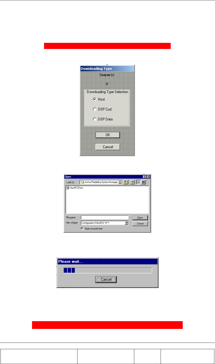
SOFTWARE DOWNLOAD GUIDE
Proprietary Information
Title: BEAMER Array System-
Assembly and Operation Manual
Doc. No.: 913000100 Rev.: 00 Page: 87 of 92
10. Enter the ID number of the required BEAMER and click O.K to continue. In case that the
particular ICU ID number does not exist in the system the following warning message will be
displayed:
ERROR : BEAM ER NUMBR 51 IS NOT RESPONDING
Otherwise the following window will be displayed:
11. Check the required file type for loading and click OK to continue . The following window will
enable to select the particular file to be loaded:
12. Select the required file from the file list and click OPEN for loading
During the loading process a status bar will be displayed:
13. Wait until the process is completed. If you wish to stop loading the file then click on the Cancel
button.
14. After the file was loaded into the BEAMER successfully the following message will be
displayed:
FILE LOAD WAS COMPLETED SUCCESSFULLY

SOFTWARE DOWNLOAD GUIDE
Proprietary Information
Title: BEAMER Array System
Assembly and Operation Manual
Doc. No.: 913000100 Rev.: 00 Page: 88 of 92
15. The new program version will operate at the end of this process and the BEAMER is
operational again.

Proprietary Information
Title: BEAMER Array System-
Assembly and Operation Manual
Doc. No.: 913000000 Rev.: 00 Page: 89 of 92
WARRANTY
The following is just to inform you that:
The manufacturer warrants its hardware products against defects in materials and workmanship for a
period of one year from receipt by the end user. During the warranty period, the manufacturer will
either, at its opinion, repair or replace products that prove to be defective.
The warranty applies to the hardware only.
Refer to RMA procedures for returned goods procedure.
Exclusions
The above warranty shall not apply to defects resulting from: improper or inadequate use,
unauthorized modifications or misuse.
Warranty Limitations
Under no circumstances will the manufacturer be liable in any way to the user for damages, including
any loss of profits, lost savings, or other incidental or consequential damages arising out of the use of,
or inability to use, the product.

Proprietary Information
Title: BEAMER Array System-
Assembly and Operation Manual
Doc. No.: 913000000 Rev.: 00 Page: 91 of 92
INDEX
acronyms, 11
array, 22, 28, 40, 41, 49, 57
assembly, 28
dismounting, 28
installation, 49
mounting, 28
attenuator, 67
battery
replacing, 26
BEAMER, 13, 34, 65, 80
configuring, 37
control, 68
defining limits, 61
installation, 65
memory, 73
software download, 73
Beamer System Manager, 55
Bias-T, 17, 27, 40, 41
BSM, 55, 58
user interface, 56
channel
receive, 49
receive, 46
transmit, 44, 49
clock, 44
comm, 59
command, 53
communication, 18
communications
serial, 25
control, 18
DC
connections, 23
distribution, 19
failure conditions, 60
file transfer, 72, 73
PC to BEAMER, 73
PC to ICU, 72
fuse, 23
GUI, 56
ICU, 14
LEDs, 57
loading
BEAMER program, 80
ICU program, 78
programs, 78
logical addresses, 35
maintainability, 20

INDEX
Proprietary Information
Title: BEAMER Array System
Assembly and Operation Manual
Doc. No.: 913000100 Rev.: 00 Page: 92 of 92
measurement conditions, 23
menus, 56
messages, 57
ICU, 14, 23, 60, 62, 69, 70, 71, 78
memory, 71
properties, 70
software download, 71
status, 69
monitoring, 18, 57
network, 18
password, 59, 78
program, 51, 78
loading, 78
receive
gain, 50
receive channel, 49
receive channel gain, 46
reports, 57
RF cable, 49
RF path, 16
Rx, 49
Rx gain, 50
Rx-ABT gain, 48
script, 53
serial communications, 25
shut down, 61
Smart-Terminal, 51
software, 58, 71, 73
downloading to BEAMER, 73
downloading to ICU, 71
user interface, 74
user interface for download, 74
sofware, 74
status reports, 57
sub-array, 63, 67
system, 62
system manager, 56
transmit channel, 49
transmit channel gain, 44
Tx, 49
Tx-ABT gain, 45
warranty, 83