Cellphone Mate SureCall
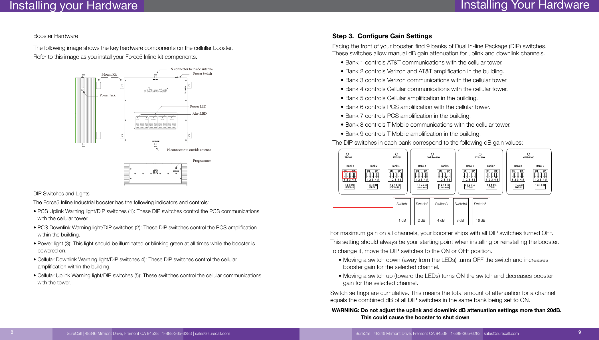
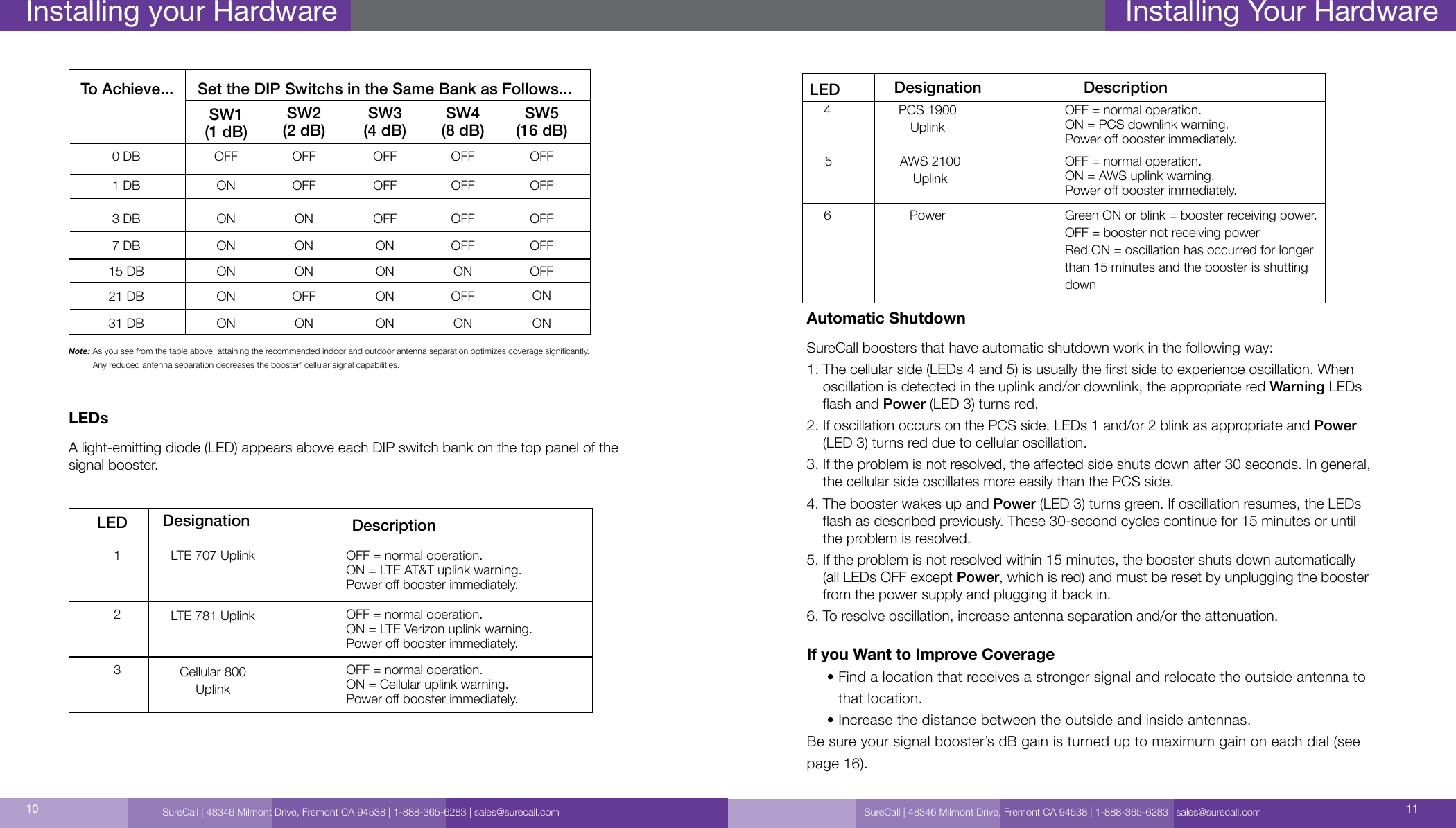
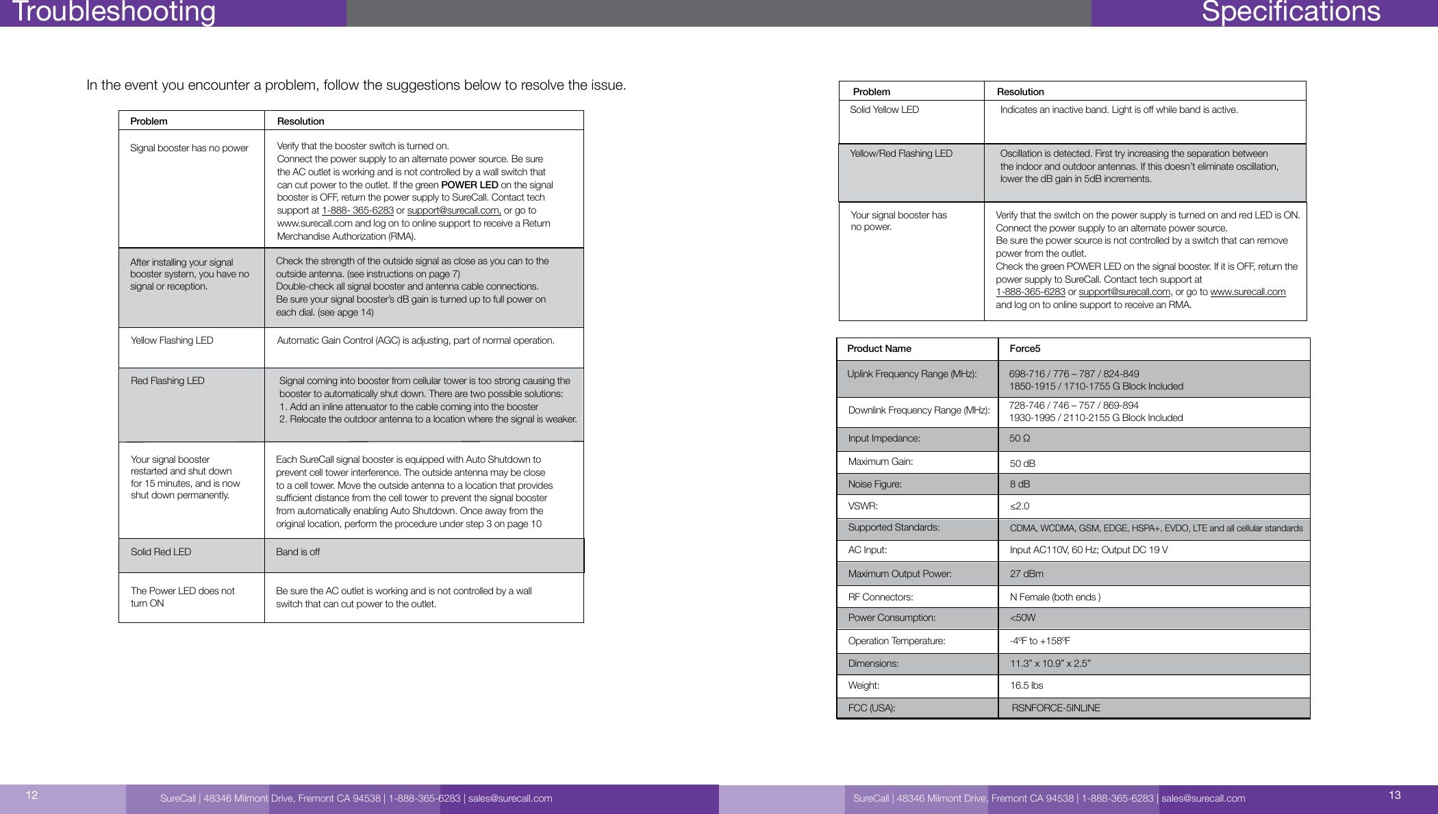
 FORCE-5INLINE 5-band signal booster User Manual Rev1

Cellphone-Mate Inc. dba SureCall 5-band signal booster Users Manual Rev1

Users Manual Rev1

Force5 Inline5-Band Cellular Booster Extender for Commercial Oces, Institutions and Housing Complexes.User GuideThis is NOT a CONSUMER device. It is designated for installation by FCC LICENSEES and QUALIFIED INSTALLERS. You MUST have an FCC LICENSE or express consent of an FCC Licensee to operate this device. Unauthorized use may result in signicant forfeiture penalties, including penalties in excess of $100,000 for each continuing violation.WARNING
How It Works                                                                                                     Pg. 3Package Contents                                                                                             Pg. 4 Before You Start                                                                                                Pg. 4Installing Your inside Antenna                                                                           Pg. 5         Installing Signal Booster                                                                                    Pg. 7Congure Gain Setting                                                                                  Pg. 9-11Troubleshooting                                                                                               Pg. 12Specication                                                                                                    Pg. 13Warranty                                                                                                       Pg. 14-15Safety Information                                                                                           Pg. 15Table of Contents How it WorksSureCall | 48346 Milmont Drive, Fremont CA 94538 | 1-888-365-6283 | sales@surecall.com 32Thank you for your purchase of the Force5 Inline signal booster. This booster is designed to extend the signal reach for Industrial Force5 Inline installations that extend beyond 80,000 square feet. This guide contains all the information you’ll need to get your Force5 Inline system up  and running. If you need any assistance while installing the product please contact tech support at 1-888-365-6283.When a project entails greater area coverage than the Force5 Industrial alone can pro-vide, additional Force5 Inline boosters can be added to areas where the signal strength is getting weak or cable lengths are too long causing dB loss. How it worksTwo common ways to increase the coverage area include:•   For areas consisting of long aisles, Force5 Inline boosters can be added where the signal falls to between -70dB and -90dB.•   For large, wide areas the Force5 Inline boosters can be daisy-chained with the use of splitters to extend the signal to remote corners.SureCall | 48346 Milmont Drive, Fremont CA 94538 | 1-888-365-6283 | sales@surecall.com
SureCall | 48346 Milmont Drive, Fremont CA 94538 | 1-888-365-6283 | sales@surecall.com 54Package Contents1. Unpack all package contents. For missing or damaged items, contact your reseller.2. Turn over the signal booster and record the model and serial number for reference:      Serial #:          Purchase Date:  3. Keep the carton and packing material to store the product in case you need to return it.Standard Force5-Inline signal booster packages include the following items:           • One power supplySignal Booster Force5 Inline BoosterBefore You StartStep 1.   Make sure you have positioned the booster close enough to an existing  electrical outlet.Step 2.   Make sure you have sucient cable length between the main cable location and booster connector.Step 3   Make sure you have sucient cable length between proposed inside antenna  location and booster connector.1.  If your indoor antenna is a dome type, mount it on the ceiling in a central location.2.  If your indoor antenna is a at panel, install it against a wall or surface projecting the area where you want reception. Point the antenna away from the outside antenna. To avoid interference stay a minimum distance of 3 feet from the panel antenna.Step 1.  Install the Inside Antenna Inside antennas come in omni-directional (dome) and at panel versions. Installing Your HardwareNote:  As you can see from the table above, acquiring the recommended inside and outside antenna separation optimizes coverage signicantly. Any reduced antenna separation reduces the booster’s coverage.Required Between Outside and Inside AntennaAntenna Separation Tableantenna separation40dB                          5-6’45dB                          15-20’50dB                          50’55dB                          60’65dB                          75-80’72dB                          100’-110’Amplier gain               Min. separation (ad)Force5 Industrial Force5 InlineSureCall | 48346 Milmont Drive, Fremont CA 94538 | 1-888-365-6283 | sales@surecall.com
SureCall | 48346 Milmont Drive, Fremont CA 94538 | 1-888-365-6283 | sales@surecall.com 76Installing Your HardwareStep 3:  Attach the N-Female connection from the interior antenna to the cable leading to the connector labeled INSIDE, on your booster.Step 4:  Tighten xing nut to secure antenna (do not over-tighten).      •  Storage and transportation: Store and place in non-extreme room-temperature and dry environment      • Attention: This antenna should not be used near open re or ameDome antennas are omni-directional interior antenna that gather signals from all sides. Range of antennas is dependent on three factors: 1) Physical obstructions 2) Power generated by booster and 3)  Reception from outside signal received and  distributed by outside antenna.Dome antennas should be mounted in an upright position for best results.Step 1:  Drill a 35mm diameter hole in the ceiling. The ceiling thickness should be 20mm, maximum.Step 2:     Unscrew xing nut from antenna. Place antenna cable through hole. Screw the xing nut back onto antenna and cable on crawl space side of ceiling and fasten.Installing Your HardwareStep 2.  Install the Signal Booster1.  Select a location for your booster close to a working AC outlet. Do not expose the signal booster to excessive heat, direct sunlight, moisture, and airtight enclosures.2.  Attach the supplied mounting kit to the booster using the supplied screws. Tighten the screws with a screwdriver until snug, then add a 1⁄4-to-1/2 turn. Do not over tighten.3.  Orient the signal booster so the LEDs and DIP switches face away from the wall and the LEDs are seen easily. Then mount the signal booster to the wall using appropriate screws and/or wall anchors.4.   Connect the main cable line from the primary booster to the booster’s connector labeled “Outside”. Hand-tighten the connection.5.  Connect the inside antenna cable to signal booster marked INSIDE. Hand-tighten the connection.6. Connect the AC power cord to the signal booster.7. Connect the plug on the other end of the 110V AC power outlet.8. Turn the booster’s power switch on.     • The signal booster turns on automatically.     • The Power LED lights up to show that the signal booster is ready for use.     • The Alert LEDs ash up to 15 seconds on each band to show the band is activated.Note:   If the Power LED does not turn ON or the Alert LEDs continue to ash, see Troubleshooting page 19. This booster is rated for 19V AV input  voltage. DO NOT use the booster with a higher voltage power supply. This can damage the booster, cause persoanl injury and viod your warrenty. SureCall | 48346 Milmont Drive, Fremont CA 94538 | 1-888-365-6283 | sales@surecall.com
SureCall | 48346 Milmont Drive, Fremont CA 94538 | 1-888-365-6283 | sales@surecall.com 98Installing your HardwareBooster HardwareThe following image shows the key hardware components on the cellullar booster.Refer to this image as you install your Force5 Inline kit components.DIP Switches and LightsThe Force5 Inline Industrial booster has the following indicators and controls:•  PCS Uplink Warning light/DIP switches (1): These DIP switches control the PCS communications with the cellular tower.•  PCS Downlink Warning light/DIP switches (2): These DIP switches control the PCS amplication within the building.•  Power light (3): This light should be illuminated or blinking green at all times while the booster is powered on.•   Cellular Downlink Warning light/DIP switches 4): These DIP switches control the cellular    amplication within the building.•  Cellular Uplink Warning light/DIP switches (5): These switches control the cellular communications with the tower.Power LEDN connector to inside antennaN connector to outside antennaAlert LEDPower Switch ProgrammerPower Jack Mount KitStep 3.  Congure Gain SettingsFacing the front of your booster, nd 9 banks of Dual In-line Package (DIP) switches. These switches allow manual dB gain attenuation for uplink and downlink channels.     • Bank 1 controls AT&T communications with the cellular tower.      • Bank 2 controls Verizon and AT&T amplication in the building.      • Bank 3 controls Verizon communications with the cellular tower      • Bank 4 controls Cellular communications with the cellular tower.      • Bank 5 controls Cellular amplication in the building.      • Bank 6 controls PCS amplication with the cellular tower.      • Bank 7 controls PCS amplication in the building.      • Bank 8 controls T-Mobile communications with the cellular tower.      • Bank 9 controls T-Mobile amplication in the building.The DIP switches in each bank correspond to the following dB gain values:For maximum gain on all channels, your booster ships with all DIP switches turned OFF. This setting should always be your starting point when installing or reinstalling the booster. To change it, move the DIP switches to the ON or OFF position.     •  Moving a switch down (away from the LEDs) turns OFF the switch and increases booster gain for the selected channel.     •  Moving a switch up (toward the LEDs) turns ON the switch and decreases booster gain for the selected channel.Switch settings are cumulative. This means the total amount of attenuation for a channel equals the combined dB of all DIP switches in the same bank being set to ON.Installing Your Hardware12345ON DIP1  2  4  8 16LTE707-ULLTE-707 LTE-78112345ON DIP1  2  4  8 16LTE-DL12345ON DIP1  2  4  8 16LTE781-UL12345ON DIP1  2  4  8 16CELLULAR-ULCellular-80012345ON DIP1  2  4  8 16CELLULAR-DL12345ON DIP1  2  4  8 16PCS-ULPCS-190012345ON DIP1  2  4  8 16PCS-DL12345ON DIP1  2  4  8 16AWS-UL AWS-DLAWS-210012345ON DIP1  2  4  8 16Bank 1 Bank 2 Bank 3 Bank 4 Bank 5 Bank 6 Bank 7 Bank 8 Bank 9Switch11 dBSwitch22 dBSwitch34 dBSwitch48 dBSwitch516 dBWARNING:  Do not adjust the uplink and downlink dB attenuation settings more than 20dB.  This could cause the booster to shut downSureCall | 48346 Milmont Drive, Fremont CA 94538 | 1-888-365-6283 | sales@surecall.com
SureCall | 48346 Milmont Drive, Fremont CA 94538 | 1-888-365-6283 | sales@surecall.com 1110 Note:   As you see from the table above, attaining the recommended indoor and outdoor antenna separation optimizes coverage signicantly.           Any reduced antenna separation decreases the booster’ cellular signal capabilities.LEDsA light-emitting diode (LED) appears above each DIP switch bank on the top panel of the signal booster.LED123LTE 707 UplinkLTE 781 UplinkCellular 800UplinkOFF = normal operation.ON = LTE AT&T uplink warning. Power o booster immediately.OFF = normal operation.ON = LTE Verizon uplink warning. Power o booster immediately.OFF = normal operation.ON = Cellular uplink warning.Power o booster immediately.Designation Description15 DB21 DB31 DBONONONONONONONOFFONONOFFONOFFONONTo Achieve... Set the DIP Switchs in the Same Bank as Follows...SW1(1 dB)0 DB1 DBOFFONOFFOFFOFFOFFOFFOFFOFFOFFSW2(2 dB)SW3(4 dB)SW4(8 dB)SW5(16 dB)3 DB ON OFFON OFF OFF7 DB ON ONON OFF OFFInstalling your HardwareLED564PCS 1900UplinkAWS 2100UplinkPowerOFF = normal operation.ON = AWS uplink warning. Power o booster immediately.Green ON or blink = booster receiving power.OFF = booster not receiving powerRed ON = oscillation has occurred for longer than 15 minutes and the booster is shutting downOFF = normal operation.ON = PCS downlink warning.Power o booster immediately.Designation DescriptionAutomatic ShutdownSureCall boosters that have automatic shutdown work in the following way:1.  The cellular side (LEDs 4 and 5) is usually the rst side to experience oscillation. When oscillation is detected in the uplink and/or downlink, the appropriate red Warning LEDs ash and Power (LED 3) turns red.2.  If oscillation occurs on the PCS side, LEDs 1 and/or 2 blink as appropriate and Power (LED 3) turns red due to cellular oscillation.3.  If the problem is not resolved, the aected side shuts down after 30 seconds. In general, the cellular side oscillates more easily than the PCS side.4.  The booster wakes up and Power (LED 3) turns green. If oscillation resumes, the LEDs ash as described previously. These 30-second cycles continue for 15 minutes or until the problem is resolved.5.  If the problem is not resolved within 15 minutes, the booster shuts down automatically (all LEDs OFF except Power, which is red) and must be reset by unplugging the booster from the power supply and plugging it back in.6. To resolve oscillation, increase antenna separation and/or the attenuation.If you Want to Improve Coverage     •  Find a location that receives a stronger signal and relocate the outside antenna to that location.      •  Increase the distance between the outside and inside antennas.Be sure your signal booster’s dB gain is turned up to maximum gain on each dial (see page 16).Installing Your HardwareSureCall | 48346 Milmont Drive, Fremont CA 94538 | 1-888-365-6283 | sales@surecall.com
SureCall | 48346 Milmont Drive, Fremont CA 94538 | 1-888-365-6283 | sales@surecall.com 1312TroubleshootingIn the event you encounter a problem, follow the suggestions below to resolve the issue.SpecicationsProduct Name Force5 Uplink Frequency Range (MHz): 698-716 / 776 – 787 / 824-849 1850-1915 / 1710-1755 G Block Included 728-746 / 746 – 757 / 869-894  1930-1995 / 2110-2155 G Block Included50 Ω50 dB8 dB≤2.0CDMA, WCDMA, GSM, EDGE, HSPA+, EVDO, LTE and all cellular standardsInput AC110V, 60 Hz; Output DC 19 V27 dBmN Female (both ends )<50W11.3” x 10.9” x 2.5”16.5 lbsRSNFORCE-5INLINEDownlink Frequency Range (MHz):Supported Standards:AC Input:VSWR:Maximum Gain:Noise Figure:Input Impedance:Maximum Output Power:RF Connectors:Power Consumption:Dimensions:Operation Temperature: -4ºF to +158ºFWeight:FCC (USA):SureCall | 48346 Milmont Drive, Fremont CA 94538 | 1-888-365-6283 | sales@surecall.comRed Flashing LEDYour signal booster restarted and shut down for 15 minutes, and is now shut down permanently.Solid Red LEDThe Power LED does not turn ONSignal booster has no powerAfter installing your signal booster system, you have no signal or reception.Verify that the booster switch is turned on.Connect the power supply to an alternate power source. Be sure the AC outlet is working and is not controlled by a wall switch that can cut power to the outlet. If the green POWER LED on the signal booster is OFF, return the power supply to SureCall. Contact tech support at 1-888- 365-6283 or support@surecall.com, or go to www.surecall.com and log on to online support to receive a Return Merchandise Authorization (RMA).Check the strength of the outside signal as close as you can to the outside antenna. (see instructions on page 7)Double-check all signal booster and antenna cable connections.Be sure your signal booster’s dB gain is turned up to full power on each dial. (see apge 14)Each SureCall signal booster is equipped with Auto Shutdown to prevent cell tower interference. The outside antenna may be close to a cell tower. Move the outside antenna to a location that provides sucient distance from the cell tower to prevent the signal booster from automatically enabling Auto Shutdown. Once away from the original location, perform the procedure under step 3 on page 10Band is oBe sure the AC outlet is working and is not controlled by a wall switch that can cut power to the outlet.Problem ResolutionYellow Flashing LED Automatic Gain Control (AGC) is adjusting, part of normal operation.Signal coming into booster from cellular tower is too  strong causing the booster to automatically shut down.  There are two possible solutions: 1. Add an inline attenuator to the cable coming into the booster  2. Relocate the outdoor antenna to a location where the signal  is weaker.Your signal booster has no power.Verify that the switch on the power supply is turned on and red LED is ON.Connect the power supply to an alternate power source.Be sure the power source is not controlled by a switch that can remove power from the outlet.Check the green POWER LED on the signal booster. If it is OFF, return the power supply to SureCall. Contact tech support at 1-888-365-6283 or support@surecall.com, or go to www.surecall.com and log on to online support to receive an RMA.Solid Yellow LEDYellow/Red Flashing LEDProblem ResolutionIndicates an inactive band. Light is o while band is active.Oscillation is detected. First try increasing the separation between  the indoor and outdoor antennas. If this doesn’t eliminate oscillation,  lower the dB gain in 5dB increments.
Three-Year Product WarrantySureCall warrants its products for three years from the date of purchase against defects in workmanship and/or materials. Specications are subject to change. The three-year warranty only applies to products meeting the latest FCC Certication Guidelines stated on 2/20/2013 and going into eect April 30, 2014. A two-year warranty applies to any products manufactured before May 1, 2014.Products returned by customers must be in their original, un-modied condition, shipped in the original or protective packaging with proof-of-purchase documentation enclosed, and a Return Merchandise Authorization (RMA) number printed clearly on the outside of the shipping container. Buyers may obtain an RMA number for warranty returns by calling the SureCall Return Department toll-free at 1-888-365-6283. Any returns received by SureCall without an RMA number clearly printed on the outside of the shipping container will be returned to sender. In order to receive full credit for signal boosters, all accessories originally included in the signal booster box must be returned with the signal booster. (The Buyer does not need to include accessories sold in addition to the signal booster, such as antennas or cables.) This warranty does not apply to any product determined by SureCall to have been subjected to misuse, abuse, neglect, or mishandling that alters or damages the product’s physical or electronic properties.SureCall warrants to the Buyer that each of its products, when shipped, will be free from defects in material and workman-ship, and will perform in full accordance with applicable specications. The limit of liability under this warranty is, at SureCall’s option, to repair or replace any product or part thereof which was purchased up to THREE YEARS after May 1, 2014 or TWO YEARS for products purchased before May 1, 2014, as determined by examination by SureCall, prove defective in material and/or workmanship. Warranty returns must rst be authorized in writing by SureCall. Disassembly of any SureCall product by anyone other than an authorized representative of SureCall voids this warranty in its entirety. SureCall reserves the right to make changes in any of its products without incurring any obligation to make the same changes on previously delivered products. As a condition to the warranties provided for herein, the Buyer will prepay the shipping charges for all products returned to SureCall for repair, and SureCall will pay the return shipping with the exception of products returned from outside the United States, in which case the Buyer will pay the shipping charges. The Buyer will pay the cost of inspecting and testing any goods returned under the warranty or otherwise, which are found to meet the applicable specications or which are not defective or not covered by this warranty. Products sold by SureCall shall not be considered defective or non-conforming to the Buyer’s order if they satisfactorily fulll the performance requirements that were published in the product specication literature, or in accordance with samples provided by SureCall. This warranty shall not apply to any products or parts thereof which have been subject to accident, negligence, alteration, abuse, or misuse. SureCall makes no warranty whatsoever in respect to accessories or parts not supplied by it.Limitations of Warranty, Damages and Liability:EXCEPT AS EXPRESSLY SET FORTH HEREIN, THERE ARE NO WARRANTIES, CONDITIONS, GUARANTEES, OR REPRE-SENTATIONS AS TO MERCHANTABILITY, FITNESS FOR A PARTICULAR PURPOSE, OR OTHER WARRANTIES, CONDITIONS, GUARANTEES, OR REPRESENTATIONS, WHETHER EXPRESSED OR IMPLIED, IN LAW OR IN FACT, ORAL OR IN WRITING.SURECALL AGGREGATE LIABILITY IN DAMAGES OR OTHERWISE SHALL NOT EXCEED THE PAYMENT, IF ANY, RECEIVED BY CELLPHONE-MATE, INC. FOR THE UNIT OF PRODUCT OR SERVICE FURNISHED OR TO BE FURNISHED, AS THE CASE MAY BE, WHICH IS THE SUBJECT OF CLAIM OR DISPUTE. IN NO EVENT SHALL SURECALL BE LIABLE FOR INCIDENTAL, CONSEQUENTIAL, OR SPECIAL DAMAGES, HOWSOEVER CAUSED. All matters regarding this warranty shall be interpreted in accordance with the laws of the State of California, and any controversy that cannot be settled directly shall be settled by arbitration in California in accordance with the rules then prevailing of the American Arbitration Associa-tion, and judgment upon the award rendered may be entered in any court having jurisdiction thereof. If one or more provisions provided herein are held to be invalid or unenforceable under applicable law, then such provision shall be ineective and excluded to the extent of such invalidity or unenforceability without aecting in any way the remaining provisions hereof.WARNING: E911 location information may not be provided or may be inaccurate for calls served BY USING THIS DEVICE.48346 Milmont DriveFremont, California 94538USA888.365.6283Fax: 510.996.7250www.surecall.comSureCall has made a good faith eort to ensure the accuracy of the information in this document and disclaims the implied warranties of merchantability and tness for a particular purpose and makes no express warranties, except as may be stated in its written agreement with and for its customers.SureCall shall not be held liable to anyone for any indirect, special or consequential damages due to omissions or  errors. The information and specications in this document are subject to change without notice. © 2014. All Rights Reserved. All  trademarks and registered trademarks are the property of their respective owners.SureCall | 48346 Milmont Drive, Fremont CA 94538 | 1-888-365-6283 | sales@surecall.com 1514Warranty WarrantySureCall | 48346 Milmont Drive, Fremont CA 94538 | 1-888-365-6283 | sales@surecall.com
 SureCall | 48346 Milmont Dirve, Fremont CA 94538 | 1-888-365-6283 | sales@surecall.comNote: This equipment has been tested and found to comply with the limits for a Class B digital device, pursuant to part 15 of the FCC Rules. These limits are designed to provide reasonable protection against harmful interference in a residential installation. This equipment generates, uses and can radiate radio frequency energy and, if not installed and used in accordance with the instructions, may cause harmful interference to radio communications. However, there is no guarantee that interference will not occur in a particular installation. If this equipment does cause harmful interference to radio or television reception, which can be determined by turning the equipment off and on, the user is encouraged to try to correct the interference by one or more of the following measures:        •  Reorient or relocate the receiving antenna.              •  Increase the separation between the equipment and receiver.                               •  Co nne ct  the  e qui pm ent into an  out le t on  a  c irc ui t di ffe ren t fr om  t hat  to w hic h th e re ce ive r is  con necte d.                                                                                                                    •  Consult the dealer or an experienced radio/TV technician for help.FCC 27.50(d)(4) Statement: Fixed, mobile and portable (hand-held) stations operating in the 1720-1755 MHz band are limited 1 Watt EIRP. Fixed stations operating in this band are limited to a maximum antenna height of 10 meters above ground. Mobile and portable stations operating in this band must employ a means for limiting power to the minimum necessary for successful communications.SureCall | 48346 Milmont Drive, Fremont CA 94538 | 1-888-365-6283 | sales@surecall.com

Navigation menu