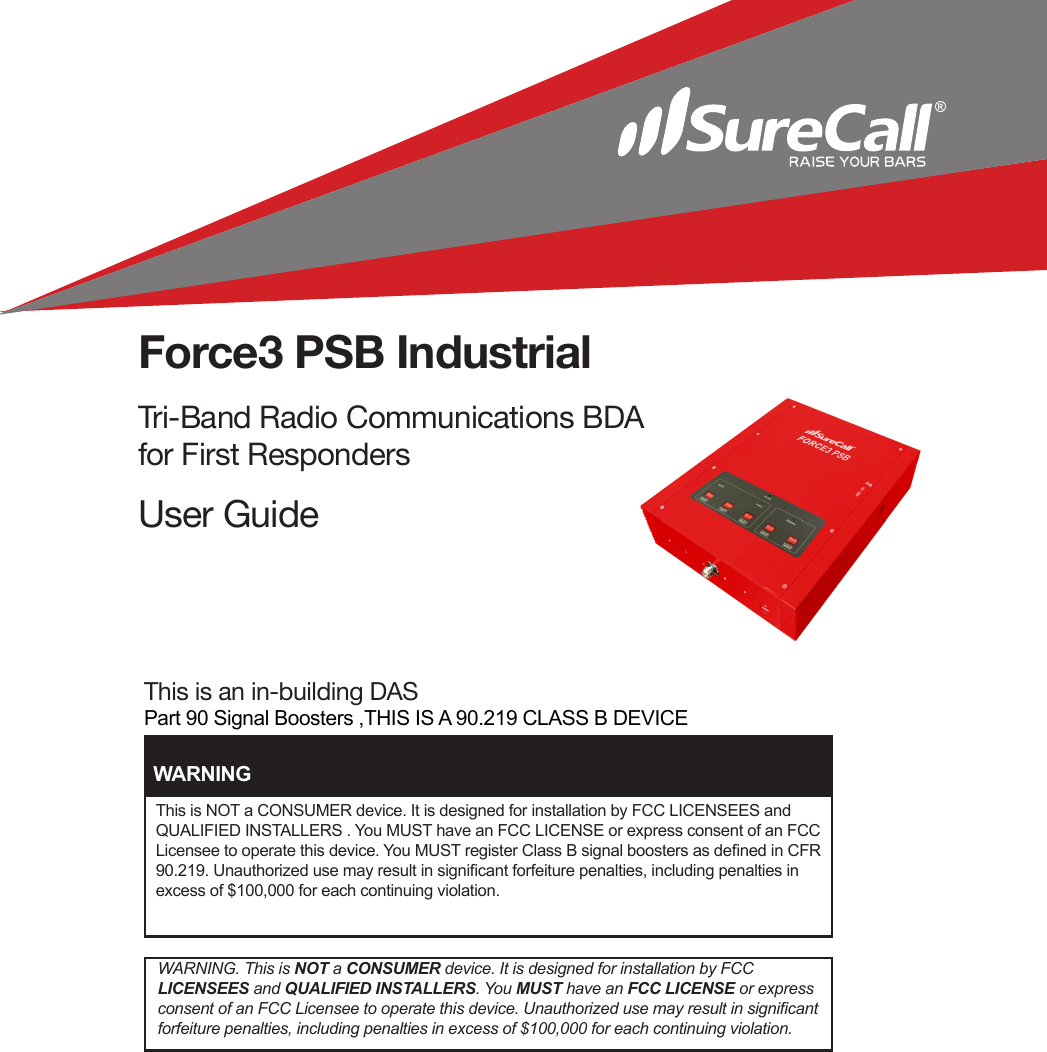
Cellphone Mate SureCall FORCE3-PSB Multi-Band Public Safety 80db Amplifier Bi-Directional in-building DAS User Manual v2

Cellphone-Mate Inc. dba SureCall Multi-Band Public Safety 80db Amplifier Bi-Directional in-building DAS Users Manual v2

Users Manual v2

This is an in-building DASPart 90 Signal Boosters ,THIS IS A 90.219 CLASS B DEVICEForce3 PSB IndustrialTri-Band Radio Communications BDA for First RespondersUser GuideThis is NOT a CONSUMER device. It is designed for installation by FCC LICENSEES and QUALIFIED INSTALLERS . You MUST have an FCC LICENSE or express consent of an FCC Licensee to operate this device. You MUST register Class B signal boosters as dened in CFR 90.219. Unauthorized use may result in signicant forfeiture penalties, including penalties in excess of $100,000 for each continuing violation.WARNINGWARNING. This is NOT a CONSUMER device. It is designed for installation by FCC  LICENSEES and QUALIFIED INSTALLERS. You MUST have an FCC LICENSE or express consent of an FCC Licensee to operate this device. Unauthorized use may result in signicant forfeiture penalties, including penalties in excess of $100,000 for each continuing violation.
SureCall | 48346 Milmont Drive, Fremont CA 94538 | 1-888-365-6283 | sales@surecall.comThis is a 90.219 Class B Device. Under Section 90.219(d)(5) of the Commission’s rules, all Part 90 Class B signal booster installations must be registered with the FCC. In February 2013, as part of the Commission’s eorts to support the continued use of signal boosters in the Private Land Mobile Radio Services and Public Safety Radio Services, the Commis-sion adopted a registration requirement for existing and future Part 90 Class B signal booster installations. The Commission found that a Class B signal booster registration system would be a valuable tool to help resolve interference should it occur.All Part 90 licensees and signal booster operators must register existing Part 90 Class B signal boosters with the Commission by November 1, 2014. In addition, any new Class B signal booster installed after November 1, 2014 must be registered prior to operation. Filing Registrations. To register a part 90 Class B signal booster, go to the part 90 Signal Booster Registration and Discovery page at www.fcc.gov/signal-boosters/registration and enter an FCC Registration Number (FRN) and Password in the upper right hand corner of the screen; then click on “LOGIN.”On the Signal Booster Information page, enter either (1) latitude and longitude (in decimal degrees) of the signal booster location and click on the “Get Address Info” button; or (2) the booster, city, and state, and click on the “Get Lat/Long button. The registration tool will provide a map of the booster location to verify that the location appears correct. Next, check the box(es) for the frequencies within the operating range of the signal booster and enter at least one call sign associated with the booster.  In addition, enter the ler’s Company Information (Com-pany Name, Company Attention, Address, Email registration, enter Signature Information (Title, Name) and click “Submit.” The system will generate a conrmation, including a booster ID number, which you may print for your records. Each booster must be submitted separately. Using the links in the upper right hand corner of the Signal Booster Conrmation page you may “Add a Booster,” “View Your Boosters” or “Log out.”Accessing Registrations. Each registration will be available to the public on the same day it is led with the Commission. Registrations may be accessed at: www.fcc.gov/signal-boosters/registration. Click on “View All Boosters” from the Part 90 Signal Booster Registration and Discovery page. The registrations can be searched and sorted by booster ID number, name of the ler, city, county, state, zip code, latitude/longitude, or call sign. For further information please contact the FCC Licensing Support Hotline at (877) 480-3201 or submit an onlinr  help request at https://esupport.c.gov/onlinerequest.htm. Hours: Monday – Friday, 8:00– 6:00 pm.2FCC Notice
 CHAPTER  1:       Introduction  1            1.1 - Package Contents                                                                                    4 1.2-Features&Benets4             1.3 - Additional Items Needed                                                                          4   1.4 - How It Works                                                                                            5CHAPTER 2: Safety                                                                                                   5  2.1 - Safety Warnings                                                                                    5-6 CHAPTER 3: Planning                                                                                                7                                                                          3.1 - Overview                                                                                                  8   3.2 - Exterior Antenna                                                                                       8  3.3 - Interior Antennas                                                                                       9   3.4 - Antenna Separation                                                                          10-11  3.5 - BDA Location                                                                                         12   3.6 - Accessories                                                                                           12   3.7 - Need Help?                                                                                           12CHAPTER 4: Installation                                                                                          13   4.1 - Selecting the Locations                                                                          13   4.2 - Soft Installation                                                                                       13   4.3 - Exterior Antenna                                                                               13-14                          4.4 - Internal Antennas                                                                                    15   4.5 - Mounting the BDA                                                                                 16CHAPTER 5: Conguration & Testing                                                                    17   5.1 - DIP Switches and Lights                                                                   17-18 5.2-InitialConguration19             5.3 - Powering on the BDA                                                                             19   5.4 - Testing                                                                                                   19   5.5 - Adjusting the BDA                                                                            19-20            5.6 - Automatic Shutdown                                                                        20-21CHAPTER 6: Warranty & Specications                                                                21  6.1 - Warranty Information                                                                               21  6.2-Specications22             6.3 - Contact Information                                                                                23SureCall | 48346 Milmont Drive, Fremont CA 94538 | 1-888-365-6283 | sales@surecall.com 3Contents
SureCall | 48346 Milmont Drive, Fremont CA 94538 | 1-888-365-6283 | sales@surecall.com4IntroductionIntroducing SureCall’s Force3 PSB Public Safety Band Amplier. Please read this entire manual be-fore proceeding with the installation. This manual applies to the Force3 PSB  model1.1 - Package ContentsYour BDA box contains the following items: • Force3 PSB Bi-Directional Amplier • Mounting kit (not shown).• DC power supply (not shown).• Wall anchors (not shown).1.2 - Features & BenetsThe Force3 PSB BDA oers the following featuresand benets:• Powerful in-building BDA with 31dB of adjustable gain level.•  Extends signals in areas with poor coverage due to geographical location and/or building design. •  Suitable for large areas up to approximately 80,000 square feet depending on outside signal strength.• Power control maintains maximum output power at 3 watts EIRP.•  Automatic oscillation detection and protection system powers down the BDA to prevent harmful radio interference.1.3 - Additional Items NeededThe Force3 PSB BDA requires the following additonal components for a complete installation: • External antenna • Lightning protector • Cable splitter if installing multiple antennas.• Sucient SC-400 ultra low loss interior/exterior cable of 50 ohm.•  Multiple antennas (omnidirectional domes and/or panels by SureCall).•  Grounded surge suppressor for DC power supply.Note:  Due to the recent change of our company name from Cellphone-Mate (CM) to SureCall (SC) we have changed the prex on all of our antennas, cables and accessories from CM to SC-.
SureCall | 48346 Milmont Drive, Fremont CA 94538 | 1-888-365-6283 | sales@surecall.com 51.4 - How It WorksThe Force3 PSB BDA amplies signals from the nearest radio tower to a building and from those radios back to the tower to compensate for weak reception caused by distance, topography, building  structure etc. The BDA receives the signal from an outside antenna, amplies that signal, and then  rebroadcasts it via the interior antenna(s) where it is picked up by radios. The interior antennas also pick up signals from radio devices and pass them to the BDA. The BDA amplies these signals and passes them to the exterior antenna for rebroadcast back to the tower.CHAPTER 2: SafetyThis chapter contains important safety information designed to prevent personal injury, equipment malfunction, and/or radio interference. You are responsible for ensuring a safe installation.2.1 - Safety Warnings•  You are responsible for knowing and following all applicable codes and regulations and for obtaining all required permits and inspections.• Follow all safety precautions contained in this Installation Manual.•  The installation process may require working in high locations such as roofs and/or ladders. Follow ap-plicable safety regulations and best practices to avoid falling. Take care not to drop objects o any high area. Cordon o ground areas directly below roof or ladder work when possible.•  Always use appropriate personal protective equipment such as goggles, gloves, hard hat, etc. as needed and as required.SafetyWARNING: FAILURE TO EXERCISE CAUTION WHEN WORKING IN HIGH AREAS COULD CAUSE A FALL AND PERSONAL INJURY.
SureCall | 48346 Milmont Drive, Fremont CA 94538 | 1-888-365-6283 | sales@surecall.com6•  Some components may be heavy and/or bulky. Always use proper lifting and carrying techniques when handling components, especially when working on a ladder, roof, or other area with a fall hazard.•  The exterior antenna must not be co-located or operating in conjunction with any other antenna.•  Always use a properly installed SureCall lightning protector between the exterior antenna and the BDA.•             Always power o the BDA before working on the roof of the building or anywhere in close proximity to the external antenna.•  Allow at least 24 inches (60cm) of separation between interior antennas and humans or animals.• Allow at least 24 inches (60cm) of separation between exterior antennas and all persons.• Comply with all antenna separation requirements to prevent signal oscillation.CAUTION: SIGNAL OSCILLATION CAN CAUSE RADIO INTERFERENCE WITH RADIO TOWERS AND RESULT IN CIVIL AND/OR CRIMINAL PENALTIES.CAUTION: FAILURE TO PROPERLY INSTALL A LIGHTNING PROTECTOR CAN RESULT IN DAM-AGE TO THE BDA, ANTENNAS, AND WIRING.Safety
SureCall | 48346 Milmont Drive, Fremont CA 94538 | 1-888-365-6283 | sales@surecall.com 7CHAPTER 3: Planning3.1 - OverviewThe general BDA installation process follows these steps:1.  Decide where to mount the exterior antenna. This will generally be on the wall or roof of the building in the location with the strongest signal. You will need to decide whether to use an omnidirectional antenna mounted vertically or a directional Yagi antenna pointed directly at the radio tower (line of sight). You must also consider attaching a grounded lightning protector between the exterior antenna and the BDA.2.  Decide where to mount the interior antenna(s), being sure to take separation requirements into account. In general, long narrow spaces will benet most from directional at-panel antennas while more square spaces will benet more from omnidirectional dome antennas.3.  Decide where to mount the BDA. This should be in a secure indoor location near a grounded power source.4.  Decide where to route the cables between the exterior antenna and the BDA and between the BDA and interior antennas.5. Install the antennas as described in their respective Installation Manuals.6. Route the cables to the BDA location.7. Install the BDA as described in this manual.8. Power on the BDA and perform the conguration and testing as described in this manual.Overview
SureCall | 48346 Milmont Drive, Fremont CA 94538 | 1-888-365-6283 | sales@surecall.com8Exterior Antenna 3.2 - Exterior AntennaYou may use either an omnidirectional antenna that covers (at areas with no obstructions)or a directional Yagi antenna (to point directly at the tower). The omnidirectional antenna receives and transmits signals over a horizontal 360-degree circle while the Yagi antenna receives and transmits sig-nals over a focused area and must be aimed directly (line of sight) toward the radio tower that provides the best signal to the building.The exterior antenna and mast (if any) must be mounted in a location that meets all of the following criteria:• Best signal strength.• Not colocated with other antennas or used in conjunction with other antennas.• Away from all power lines.• 6’ from lightning rod antennas.• 24” from all persons.These distances are general guidelines only; refer to the applicable building and electrical codes in  your area to determine local requirements.
SureCall | 48346 Milmont Drive, Fremont CA 94538 | 1-888-365-6283 | sales@surecall.com 9Interior Antenna3.3 - Interior AntennasYou may use any combination of omnidirectional (dome) and/or directional (at panel) interior antennas needed to obtain optimal signal strength throughout the building or installation area. Dome antennas provide 360-degree hemispherical coverage suitable for mostly square areas while at panel antennas provide a focused zone of coverage suitable for long narrow areas. The follow-ing example uses two dome antennas and one panel antenna to provide full coverage (exterior Yagi antenna also shown):Keep in mind that oor structures in multistory buildings can cause signicant signal loss, which means that you may need to install interior antennas on more than one oor. Here is an example of  a multistory installation:
SureCall | 48346 Milmont Drive, Fremont CA 94538 | 1-888-365-6283 | sales@surecall.com10Note: Vertical separation is more important than horizontal separation. If you are unable to obtain the required separation horizontally, try raising the exterior antenna. You may also try reducing the BDA gain as described in Chapter 5 of this manual.Antenna Separation3.4 - Antenna SeparationProper antenna separation is essential in order to prevent signal oscillation (feedback) that caninterfere with the radio tower. Separation is measured in a straight line from the exterior antenna to the closest interior antenna. The closest allowable distance depends on a number of factors such as BDA gain level, building material, etc. Recommended separation distances are:Note: You may or may not need antennas on every oor of a multistory building depending on factors such as building material, BDA gain, etc.40dB                          5-6’45dB                          15-20’50dB                          50’55dB                          60’65dB                          75-80’70dB                          100’75dB                          100’-120’80dB                          120’-180’Amplier gain                    Min. separation (ad)
SureCall | 48346 Milmont Drive, Fremont CA 94538 | 1-888-365-6283 | sales@surecall.com 11Antenna SeparationYou may mix and match dome and directional antennas as needed to obtain proper coverage throughout the building or area where you need to boost the signal. If you are using a Yagi exterior antenna, you should normally aim it away from all interior antennas regardless of separation to prevent oscillation.CAUTION: SIGNAL OSCILLATION CAN CAUSE RADIO INTERFERENCE WITH RADIO TOWERS AND RESULT IN CIVIL AND/OR CRIMINAL PENALTIES.
SureCall | 48346 Milmont Drive, Fremont CA 94538 | 1-888-365-6283 | sales@surecall.com12BDA Location3.6 - BDA LocationSelect an indoor location for the BDA that meets the following criteria: • Wall or ceiling mounts are acceptable.• Near a properly grounded 110VAC outlet.• Not in a tightly enclosed or overly hot space.• All power and warning lights easily visible.• Least amount of cable to connect all antennas.3.7 - AccessoriesThe nal step in the planning process is to make sure you have all of the necessary accessories to complete the installation. You will need all of the items listed in Chapter 1 of this manual plus some or all of the following:• Cable clips: Use these to secure the cables to interior and exterior walls/ceilings.• Appropriately rated sealant/caulking: Use this to waterproof the opening where the cable from theexterior antenna enters the building, if needed.• Hand and/or power tools: As needed to complete the installation.• Personal Equipment (PPE): Use all PPE required by local codes and/or best practices to help ensure personal safety during installation.Note: You may need to obtain a permit from your local building department to install the BDA and antennas. Check your local building and/or electrical codes. 3.8 - Need Help?If you need help planning your installation, please contact a qualied installer, the reseller from whom you purchased the BDA, or SureCall.CAUTION: YOU ARE RESPONSIBLE FOR ENSURING THAT THE INSTALLATION MEETS ALL APPLICABLE CODES.
SureCall | 48346 Milmont Drive, Fremont CA 94538 | 1-888-365-6283 | sales@surecall.com 13InstallationChapter 4. InstallationThis chapter describes how to install the BDA and antennas for best results.4.1 - Selecting the LocationsSelect the locations for the exterior antenna, interior antenna(s), BDA, cables, and accessories as described in the previous chapter.4.2 - Soft InstallationPerform a “soft” installation of all components to test signal coverage and oscillation before making the installation permanent. Avoid making holes or other permanent xtures during this initial phase. Please refer to Chapter 5 of this manual for conguration and testing instructions. Proceed with the nal installation once conguration and testing are complete. 4.3 - Exterior AntennaMount the exterior antenna in the location you selected during the planning process. Be sure to follow all of the instructions included with the antenna to ensure a safe installation. Remember:• An omnidirectional antenna must be mounted vertically.• A Yagi antenna must be mounted horizontally and be aimed at the desired radio tower (line of sight).CAUTION: FAILURE TO PROPERLY PLAN THE BDA INSTALLATION CAN CAUSE SIGNAL OSCILLATION AND/OR OTHER EQUIPMENT MALFUNCTION.CAUTION: MOUNT THE EXTERIOR ANTENNA ON A FIXED STRUCTURE.
SureCall | 48346 Milmont Drive, Fremont CA 94538 | 1-888-365-6283 | sales@surecall.com14InstallationWARNING: FAILURE TO EXERCISE CAUTION WHEN WORKING IN HIGH AREAS COULD CAUSE A FALL AND PERSONAL INJURY.CAUTION: AVOID AIMING A YAGI ANTENNA TOWARD ANY INTERIOR ANTENNA.1. Mount the antenna.2. Connect a length of cable to the antenna and tighten until hand-tight.3. Run the cable along the planned route.4. Install a properly grounded SC-LP lightning protector.5. Seal any holes you make in the outside of the building with appropriate caulking or sealant.WARNING: DO NOT TOUCH ANY LIVE ELECTRICAL WIRES OR ALLOW THE ANTENNA OR CABLING TO TOUCH ANY LIVE ELECTRICAL WIRES.
SureCall | 48346 Milmont Drive, Fremont CA 94538 | 1-888-365-6283 | sales@surecall.com 15 CAUTION: VERIFY THAT ALL INTERIOR ANTENNAS MEET THE SEPARATION REQUIREMENTSDESCRIBED IN THE PREVIOUS CHAPTER AND THAT NO ANTENNA IS AIMED TOWARD THE EXTERIOR ANTENNA.CAUTION: DO NOT CONNECT AN INTERIOR ANTENNA TO THE SPLITTER INPUT.4.4 - Internal AntennasMount the interior antenna(s) in the location(s) you selected during the planning process. Be sure to follow the instructions included with the antenna(s) for a safe installation. Remember:•  Dome antennas should be mounted in the ceiling as close to the center of the desired coverage area as possible with the domed side pointing down.•                  Flat panel antennas should be wall-mounted as close as possible to center of the wall at one end of long narrow space.1. Mount the antenna. 2. Connect a length of cable to the antenna and tighten until hand-tight. 3. If you are installing multiple antennas, run the cable to the splitter location and connect the cable to one of the outputs on the splitter.4. Connect another length of cable to the input side of the splitter (if used) and run this cable to the BDA location.5. It is important to keep the cable runs equal or use taps to ensure a harmonious install.Installation
SureCall | 48346 Milmont Drive, Fremont CA 94538 | 1-888-365-6283 | sales@surecall.com164.5 - Mounting the BDAMount the BDA as follows:1. Verify that the selected location meets all of the criteria described in the previous chapter. 2. Attach the included mounting kit to the BDA using the screws provided. Tighten the screws by hand with a screwdriver until tight plus 1/4 to 1/2 turn. Do not over-tighten.3. Mount 24” x 24”, 3⁄4” thick sheet of plywood on top of sheetrock into wall studs where the BDA is to be situated. Plywood should be ush against wall. Once mounted, screw the BDA to the plywood sheet. The top side of the BDA with the lights and DIP switches should be facing away from the wall and be plainly visible standing near the BDA.4. Connect the exterior antenna cable to the Outside Antenna port on the BDA.5. Connect the interior antenna cable to the Inside Antenna port on the BDA.6. Verify that all cable connections are tight and that the exterior and interior antennas are connected to the proper jacks.CAUTION: DO NOT POWER ON THE BDA UNTIL INSTRUCTED TO DO SO.CAUTION: NEVER POWER ON THE BDA WHEN ANY ANTENNAS ARE DISCONNECTED AS THISCOULD DAMAGE THE BDA.Installation
SureCall | 48346 Milmont Drive, Fremont CA 94538 | 1-888-365-6283 | sales@surecall.com 17CHAPTER 5: Conguration & TestingThe Force3 PSB has ve dipswitches. Below is an image of the dip-switches and the frequency bands they utilize for attenuation. Next to the image is a general attenuation guide.DIP Switches1) PS 700 DL dip wsitches control 700 band downlink2) PS UL dip wsitches control 700 band and 800 band uplink3) PS 800 DL dip wsitches control 800 band downlink4) SMR 900 UL dip wsitches control 900 band uplink5) SMR 900 UL dip wsitches control 900 band downlinkSwitch 1 (1dB) + Switch 2 (2dB) = 3dB attenuationSwitch 1 (1dB) + Switch 2 (2dB) + Switch 3 (4dB) = 7dB attenuationSwitch 1 (1dB) + Switch 2 (2dB) + Switch 3 (4dB) + Switch 4 (8dB) = 15dB attenuationSwitch 1 (1dB) + Switch 2 (2dB) + Switch 3 (4dB) + Switch 4 (8dB) + Switch 5 (16dB) = 31dB attenuationSwitch 1       Switch 2          Switch 3          Switch 4         Switch 5  1dB                 2dB                   4dB               8dB                  16dBConguration and Testing
SureCall | 48346 Milmont Drive, Fremont CA 94538 | 1-888-365-6283 | sales@surecall.com18Each bank of DIP switches contain ve switches.• Turning a switch OFF increases BDA gain for the selected channel.• Turning that switch ON decreases BDA gain for the selected channel.From left to right, the DIP switches in each bank provide 1, 2, 4, 8, and 16 dB of attenuation (reduced amplication). These switches are cumulative, meaning that the total amount of attenuation for a channel is equal to the combined dB of all ON DIP switches in the corresponding bank. For example:• Turning all switches OFF = 0dB attenuation (BDA is at full gain).• Turning ON Switch #1 in a bank = 1dB attenuation (BDA maximum gain is reduced by 1dB).• Turning ON Switches #1, 3, and 5 in a bank = 1+4+16dB attenuation = 21dB attenuation.For example, in an 80dB BDA, this means the selected channel would be reduced to 59dB (80db -21db).• Turning ON all switches in a bank = 1+2+4+8+16dB attenuation = 31dB attenuationFor example, in an 80 dB BDA, that means that the selected channel would be reduced to 49dB (80dB-31dB).When the BDA is powered on:• The green Power light (4) should illuminate.• If any of the bands are oscillating, the corresponding Band lights (1,2,3) will ash red and that band will ash red and that band will shut down.Note: When the BDA is turned on, the Band lights will ash red and yellow for approximately 10 sec-onds.Conguration and Testing123 4 5124 8 16UPLINK123 4 5124 8 16DOWNLINK12 34
SureCall | 48346 Milmont Drive, Fremont CA 94538 | 1-888-365-6283 | sales@surecall.com 195.2 - Initial CongurationBy default, your BDA ships with all DIP switches turned OFF to provide maximum gain in all channels. This should always be your starting point whenever installing or reinstalling the BDA.5.3 - Powering on the BDATo power on the BDA:1. Make sure that exterior and interior antenna cables are rmly connected to the proper ports on the BDA.2. Plug a surge suppressor into a grounded 110VAC wall outlet.3. Plug the AC end of the power adapter that came with the BDA into the surge suppressor.4. Plug the DC end of the power adapter into the Power port on the BDA.5. Verify that the green Power light is illuminated.5.4 – TestingOnce the BDA is powered on and no Warning lights are illuminated, walk around the entire area to test the voice and/or data signal. Rene the antenna locations and/or gain levels as needed, and then complete the permanent installation once the system is working as desired.5.5 - Adjusting the BDAKeep the following points in mind when adjusting the BDA:• Full power is not always your best option. Your goal is to obtain a usable radio signal in as many areas of the building as possible. A successful installation means that you can make calls without dropping and/or have a reliable data connection.5. Verify that the green Power light is illuminated.CAUTION: ONLY USE THE POWER SUPPLY INCLUDED WITH THE BDA. USE OF ANOTHER POWER SUPPLY COULD DAMAGE THE BDA AND/OR POWER SUPPLY.CAUTION: DO NOT PROCEED BEYOND THIS POINT UNTIL THE BDA IS POWERED ON AND NO RED WARNING LIGHTS ARE ILLUMINATED.Conguration and Testing
SureCall | 48346 Milmont Drive, Fremont CA 94538 | 1-888-365-6283 | sales@surecall.com20• Do not expect to see full reception everywhere in the building as this is practically impossible. • A good rule of thumb is that increasing gain by 6dB doubles the coverage distance of the interior antennas. Start at the lowest gain setting and increase gain gradually as needed.• If one or more red Warning lights comes on, that indicates that there’s oscillation in that band and the band will immediately shut down. If the dB gain is not adjusted, the Warning light will continue ashing. The BDA will power down and will then wake every 30 seconds for the next 15 minutes to see if the problem has been resolved. If the problem has not been resolved after 15 minutes, the BDA will shut o and will need to be unplugged and plugged back in again to reset.• You may see oscillation in any of the bands (see Section 5.6).• If you can’t get the system to work properly, you may need to install an additional interior antenna and/or a dierent type of interior antenna and/or relocate interior antennas.Note: In general, the uplink and downlink DIP switches should be set identically but this is not always the case.5.6 - Automatic ShutdownIf equipped, the Force3 PSB BDA includes an automatic shutdown feature that works in the following sequence:1. When oscillation is detected in the uplink and/or downlink, the appropriate Warning light(s) will begin ashing red and the Power light (light 5 in the diagram on Page 18) remain green.2. If oscillation occurs on any other band, lights 6 and/or 7, 8, 9, and 10 will blink as appropriate.3. If the electrical current powering the BDA is too weak or too strong, lights 6 and/or 7, 8, 9, and 10 will blink yellow.4. If the problem is not resolved, the aected side will shut down for 30 seconds.5. The BDA will wake back up. When this occurs, the power light will be green. If oscillation re-sumes, the lights will ash as previously described. These 30-second cycles will continue for 15 minutes or until the problem is resolved.Conguration and Testing
SureCall | 48346 Milmont Drive, Fremont CA 94538 | 1-888-365-6283 | sales@surecall.com 216. If the problem is not resolved within 15 minutes, the BDA will shut down (all lights o except the Power light, which is green) and must be reset by unplugging it from the power supply and plug-ging it back in.To resolve oscillation, increase the antenna separation (Section 3.4) and/or the attenuation (Section 5.1).7. Each band on the BDA works independently from other bands. Therefore, Band lights will react accordingly.CHAPTER 6: WarrantyThis chapter contains the warranty information for your SureCall product and also contains information on how to contact the company.6.1 - Warranty PeriodsYour warranty includes the following periods:• Three-Year Product Warranty: SureCall products are covered under a three-year product warranty from the date of purchase. This protects the customer from any defects or problems the product may have that are solely the fault of SureCall. Incorrect installation or misuse will void this warranty. Upon the return of a defective product, SureCall will issue the customer a working replacement. All returned packages should contain all products distributed.• Five-Year Extended Product Warranty: A ve year warranty is available for purchase on any products sold by SureCall. A ve-year warranty must be obtained at the time of purchase. This warranty adds an additional two years to the three year warranty we provide. All regulations still apply. Insert Warranty information from previous User’s Guide.6.3 - Contact InformationYou may consult a SureCall customer service agent directly by contacting us as follows:• Our online support center is at www.surecall.com/HelpDeskService.aspx If needed, you can create an online support ticket. This is the fastest and best way to get support for your product.• Call us at (888)365-6283.Warranty
SureCall | 48346 Milmont Drive, Fremont CA 94538 | 1-888-365-6283 | sales@surecall.comThree-Year Product WarrantySureCall warrants its products for three years from the date of purchase against defects in workmanship and/or materials. Specications are subject to change. The three-year warranty only applies to products meeting the latest FCC Certication Guidelines stated on 2/20/2013 and going into eect April 30, 2014. A two-year warranty applies to any products manufactured before May 1, 2014.Products returned by customers must be in their original, un-modied condition, shipped in the original or protective packaging with proof-of-purchase documentation enclosed, and a Return Merchandise Authorization (RMA) number printed clearly on the outside of the shipping container. Buyers may obtain an RMA number for warranty returns by calling the SureCall Return Department toll-free at  1-888-365-6283. Any returns received by SureCall without an RMA number clearly printed on the outside of the shipping container will be returned to sender. In order to receive full credit for signal BDAs, all accessories originally included in the signal BDA box must be returned with the signal BDA. (The Buyer does not need to include accessories sold in addition to the signal BDA, such as antennas or cables.) Specifications are subject to change. Specifications contained within apply only to products meeting the latest FCC Certification Guidelines of 2/20/2013.Uplink Frequency Range:Force3 PSB Product Name80 dB26dBm² 8 dB² 2.0Public Safety 700 and 800 and SMR 900110 V, 60 Hz                         SC-400 N Female (both ends )90W-4¼F to +158¼F15-1/2" X 11  X 3-1/2"19.5 lbs.Downlink Frequency Range:Supported Standards:AC Input:VSWR:Maximum Gain:Noise Figure:Maximum RF Output Power:Cable:RF Connectors:Power Consumption:Operating Temperature:Dimensions:Weight:RSNFORCE3-PSBFCC (USA):788-805 / 806-824 / 935-940 (Including D Block) 758-775 / 851-869 / 896-901 (Including D Block)31 dBGain Adjustment 31.5dBmP1dB: 22Specications
Limitations of Warranty, Damages and Liability:EXCEPT AS EXPRESSLY SET FORTH HEREIN, THERE ARE NO WARRANTIES, CONDITIONS, GUARANTEES, OR REPRE-SENTATIONS AS TO MERCHANTABILITY, FITNESS FOR A PARTICULAR PURPOSE, OR OTHER WARRANTIES, CONDITIONS, GUARANTEES, OR REPRESENTATIONS, WHETHER EXPRESSED OR IMPLIED, IN LAW OR IN FACT, ORAL OR IN WRITING.SURECALL AGGREGATE LIABILITY IN DAMAGES OR OTHERWISE SHALL NOT EXCEED THE PAYMENT, IF ANY, RECEIVED BY CELLPHONE-MATE, INC. FOR THE UNIT OF PRODUCT OR SERVICE FURNISHED OR TO BE FURNISHED, AS THE CASE MAY BE, WHICH IS THE SUBJECT OF CLAIM OR DISPUTE. IN NO EVENT SHALL SURECALL BE LIABLE FOR INCIDENTAL, CONSEQUENTIAL, OR SPECIAL DAMAGES, HOWSOEVER CAUSED. All matters regarding this warranty shall be interpreted in accordance with the laws of the State of California, and any controversy that cannot be settled directly shall be settled by arbitration in California in accordance with the rules then prevailing of the American Arbitration Associa-tion, and judgment upon the award rendered may be entered in any court having jurisdiction thereof. If one or more provisions provided hereinareheldtobeinvalidorunenforceableunderapplicablelaw,thensuchprovisionshallbeineectiveandexcludedtotheextentofsuchinvalidityorunenforceabilitywithoutaectinginanywaytheremainingprovisionshereof.WARNING: E911 location information may not be provided or may be inaccurate for calls served BY USING THIS DEVICE.48346 Milmont DriveFremont, California 94538USA888.365.6283Fax: 510.996.7250www.surecall.comSureCallhasmadeagoodfaitheorttoensuretheaccuracyoftheinformationinthisdocumentanddisclaimstheimpliedwarrantiesofmerchantabilityandtnessforaparticularpurposeandmakesnoexpresswarranties,exceptasmaybestatedinitswrittenagreementwithand for its customers.SureCall shall not be held liable to anyone for any indirect, special or consequential damages due to omissions or  errors.Theinformationandspecicationsinthisdocumentaresubjecttochangewithoutnotice.©2015.AllRightsReserved.All trademarks and registered trademarks are the property of their respective owners.This warranty does not apply to any product determined by SureCall to have been subjected to misuse, abuse, neglect, or mis-handling that alters or damages the product’s physical or electronic properties.SureCall warrants to the Buyer that each of its products, when shipped, will be free from defects in material and workmanship, and will perform in full accordance with applicable specications. The limit of liability under this warranty is, at SureCall’s option, to repair or replace any product or part thereof which was purchased up to THREE YEARS after May 1, 2014 or TWO YEARS for products purchased before May 1, 2014, as determined by examination by SureCall, prove defective in material and/or work-manship. Warranty returns must rst be authorized in writing by SureCall. Disassembly of any SureCall product by anyone other than an authorized representative of SureCall voids this warranty in its entirety. SureCall reserves the right to make changes in any of its products without incurring any obligation to make the same changes on previously delivered products. As a condition to the warranties provided for herein, the Buyer will prepay the shipping charges for all products returned to Sure-Call for repair, and SureCall will pay the return shipping with the exception of products returned from outside the United States, in which case the Buyer will pay the shipping charges. The Buyer will pay the cost of inspecting and testing any goods returned under the warranty or otherwise, which are found to meet the applicable specications or which are not defective or not covered by this warranty. Products sold by SureCall shall not be considered defective or non-conforming to the Buyer’s order if they satisfactorily fulll the performance requirements that were published in the product specication literature, or in accordance with samples provided by SureCall. This warranty shall not apply to any products or parts thereof which have been subject to accident, negligence, altera-tion, abuse, or misuse. SureCall makes no warranty whatsoever in respect to accessories or parts not supplied by it.SureCall | 48346 Milmont Drive, Fremont CA 94538 | 1-888-365-6283 | sales@surecall.com 23Warranty

Navigation menu