Cellphone Mate SureCall FORCE5S 5 Band Cellular Booster with Built in Sentry monitoring system User Manual
Cellphone-Mate Inc. dba SureCall 5 Band Cellular Booster with Built in Sentry monitoring system Users Manual
Users Manual
Force5 2.0™
Voice and 4G LTE Cellular Booster Kit with Built-in Sentry
2
Thank you for purchasing SureCall’s Force5 2.0 voice and 4G LTE cellular booster kit with built-in Sentry. Force5
2.0 was specically designed to eliminate frustrations over dropped calls and slow 4G data along with the ability to
monitor and adjust booster performance o site.
If you have any questions during setup, please reach out to our US-based experienced support technicians:
Call: 1-888-365-6283
Email: support@surecall.com
Or, chat: www.surecall.com, 7:00 am – 5:00 pm PST, Monday – Friday
Watch installation,
optimization and
troubleshooting techniques
in our SureCall University
YouTube channel
@SureCall Stay up to date with all
things SureCall
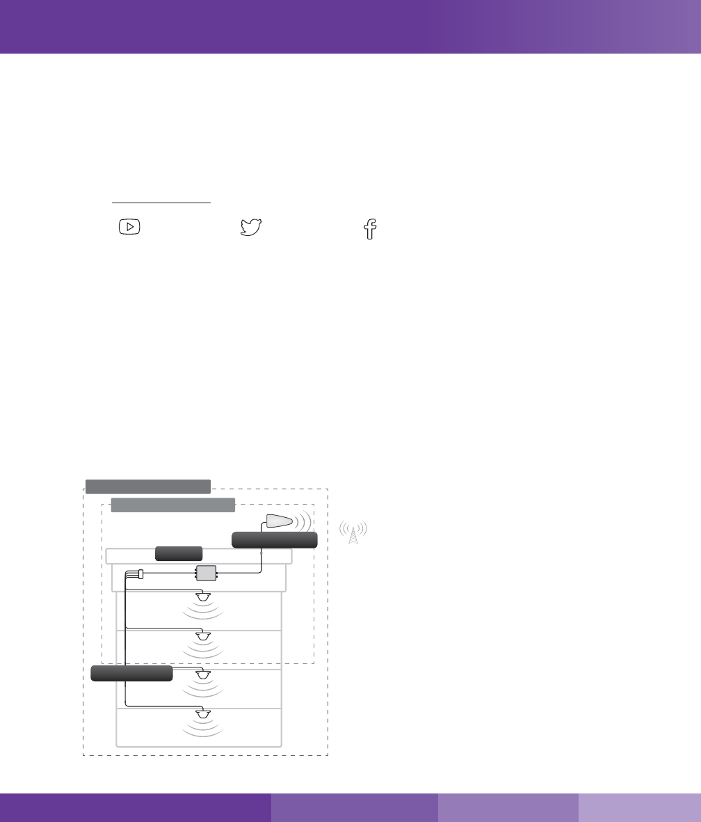
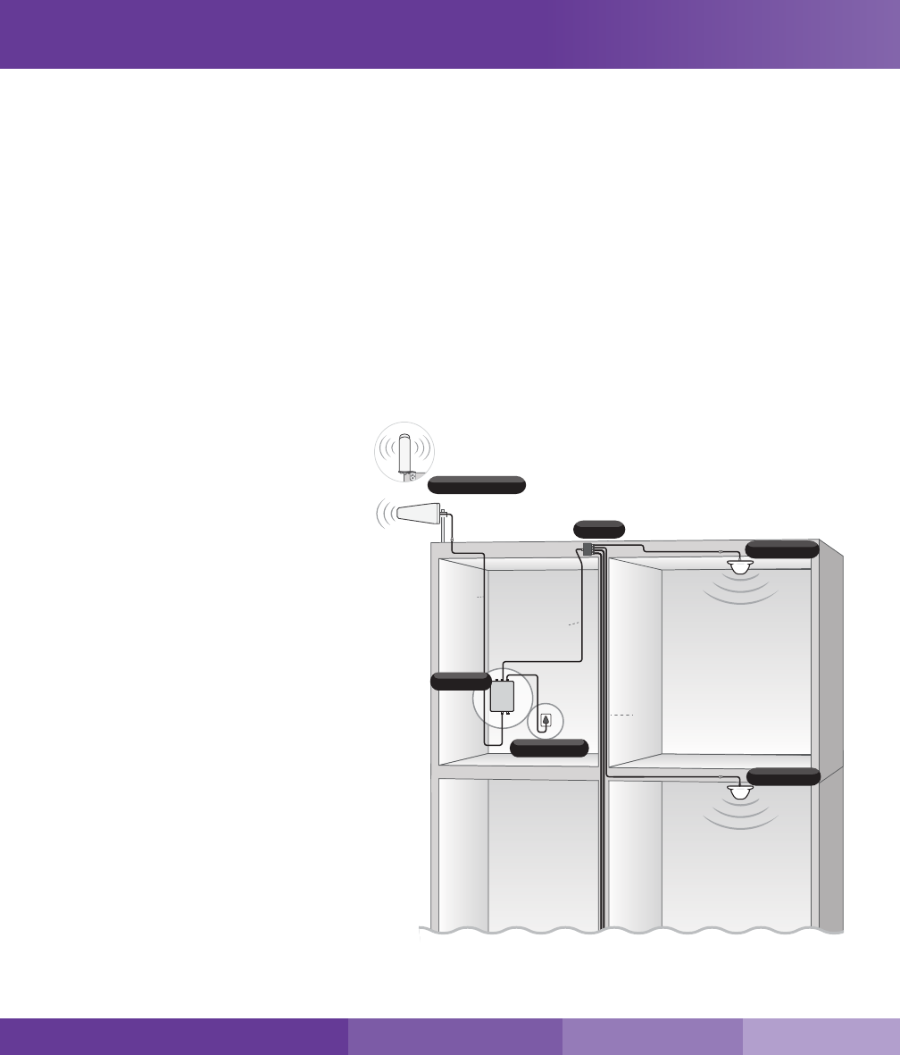
How It Works
SureCall’s Force5 2.0 cellular boosting function uses a high-quality bidirectional signal booster that enhances
signals to areas that are prone to weak cellular coverage. It works with two types of antennas:
1) An outdoor antenna that communicates with the cell tower.
2) A set of Indoor antennas that communicate with your mobile devices.
Signals sent from a cell tower are received by the outdoor antenna, amplied by the booster and then sent to your
phone via the indoor antennas. When your phone transmits, the signal is sent to the indoor antennas, and then
sent to the cell tower via the outdoor antenna.
How It Works
b) Two indoor antenna option
a) Four Indoor antenna option
Booster
Outdoor Antenna
Indoor Antennas
SureCall | 48346 Milmont Drive, Fremont CA 94538 | 1-888-365-6283 | support@surecall.com

3
SureCall | 48346 Milmont Drive, Fremont CA 94538 | 1-888-365-6283 | support@surecall.com
Table of Contents
How It Works .................................................................................................................................................. 2
Package Contents .........................................................................................................................................4
Kit Options .....................................................................................................................................................4
Before Installation ..........................................................................................................................................6
Installation Overview ......................................................................................................................................6
Section 1: Booster Installation ......................................................................................................... 7
Step 1. Find the Area Outside with the Strongest Signal .............................................................................7
Step 2. Install the Outdoor Antenna...............................................................................................................7
Installing a Yagi Antenna ............................................................................................................................8
Installing an Optional Omni Antenna ...........................................................................................................9
Step 3. Install the Indoor Antennas .............................................................................................................10
For Each Indoor Dome Antenna: .............................................................................................................10
Step 4. Install the Signal Booster .................................................................................................................12
Booster Conguration ..................................................................................................................................13
DIP Switches and Lights ..........................................................................................................................13
Adjusting Booster Cellular Attenuation .....................................................................................................14
Section 2: Booster Operation and Troubleshooting ..................................................................... 16
Troubleshooting ...........................................................................................................................................17
Section 3: Built-in Sentry ............................................................................................................... 18
Sentry Hardware Installation ........................................................................................................................18
Sentry Software Installation .........................................................................................................................18
Section 4: Specications ............................................................................................................... 26
Kitting Information ........................................................................................................................................27
Section 5: FCC & Safety Information ............................................................................................. 28
Section 6: Three-Year Product Warranty ....................................................................................... 29
Limitations of Warranty, Damages and Liability: ........................................................................................29
Table of Contents
4
Package Contents
1. Unpack all package contents. For missing or damaged items, contact your reseller. Keep the carton and
packing material to store the product in case you need to return it.
2. Turn over the signal booster and record the model and serial number for reference:
Serial #: _____________________________________________________________________________
Purchase Date: _______________________________________________________________________
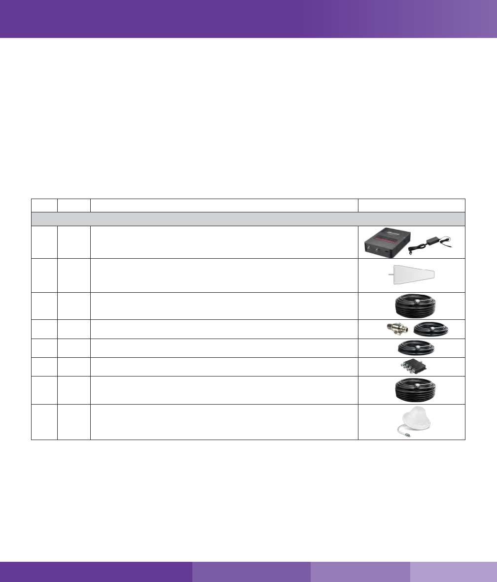
Kit Options
Force5 2.0 signal booster kits:
QTY Description
Included in kit 1
🅐1/ea SureCall Force5 2.0 booster and power supply
🅑1 Outdoor Yagi antenna
🅒1 30 ft. length of SC-400 coax cable (connects booster to outdoor antenna)
🅓1/ea Lightning protector and 2 ft. SC-400 NN cable (connects to Lightning protector)
🅔1 20 ft. cable to connect to splitter
🅕1 4-Way splitter
🅖4 75 ft. length of SC-400 coax cable (connects the booster to the indoor antennas)
🅗4Indoor dome antennas
Package Contents
SureCall | 48346 Milmont Drive, Fremont CA 94538 | 1-888-365-6283 | support@surecall.com
5
SureCall | 48346 Milmont Drive, Fremont CA 94538 | 1-888-365-6283 | support@surecall.com
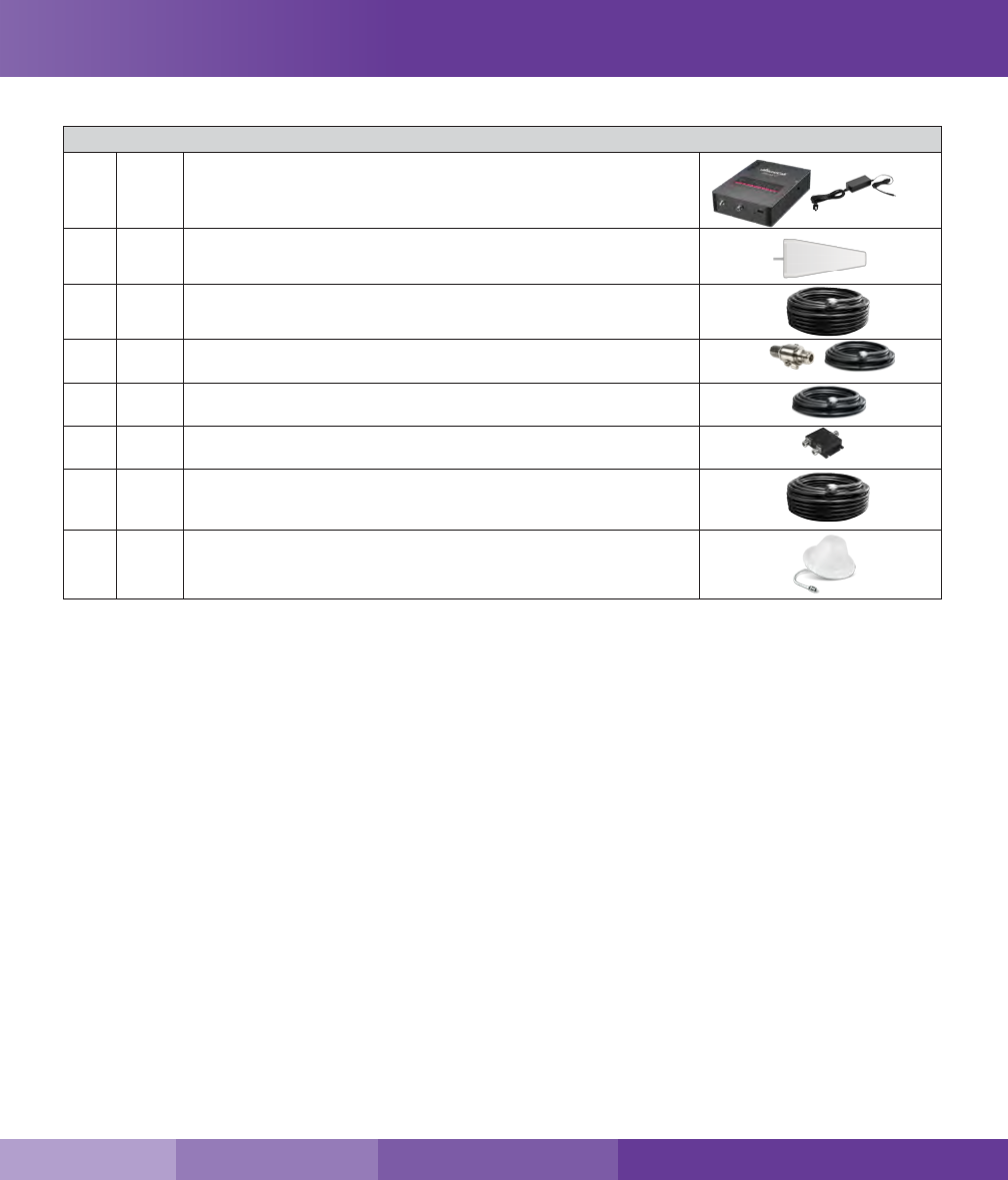
Package Contents
Included in kit 2
🅐1/ea SureCall Force5 2.0 booster and power supply
🅑1 Outdoor Yagi antenna
🅒1 30 ft. length of SC-400 coax cable (connects booster to outdoor antenna)
🅓1/ea Lightning protector and 2 ft. SC-400 NN cable (connects to Lightning
protector)
🅔1 20 ft. cable to connect to splitter
🅕1 2-Way splitter
🅖2 75 ft. length of SC-400 coax cable (connects the booster to the indoor
antennas)
🅗2Indoor dome antennas

6
Before Installation
Before installation, make note of these important factors:
• A “soft install” is recommended for each section of your installation before permanent placement of
parts.
• The booster will need to be close enough to an existing electrical outlet.
• A minimum of 50 ft. of separation between the outdoor antenna and indoor antennas is recommended.
• There will need to be sucient cable length between planned outdoor antenna location and booster connector.
• There will need to be sucient cable length between planned indoor antenna location and booster connector.
Additional cable may be purchased if needed.
Installation Overview
1. Find the outside area that has the strongest signal. (See page 7).
2. Install the outdoor antenna in the area identied in step 1. (See page 7).
3. Install the indoor antennas where increased signal is needed. (See page 10).
4. Mount the signal booster, connect the outdoor and indoor antenna cables to the signal booster, and connect
the booster to an AC power source. (See page 12).
Before Installation
FCC 27.5 (d)(4) Statement: Fixed, mobile, and portable (hand-held) stations operating in the 1710-1755 MHz band as well as mobile and
portable stations operating in the 1695-1710 MHz and 1755-1780 MHz bands are limited to 1 watt EIRP. Fixed stations operating in the
1710-1755 MHz band are limited to a maximum antenna height of 10 meters above ground. Mobile and portable stations operating in these
bands must employ a means for limiting power to the minimum necessary for successful communications.
SureCall | 48346 Milmont Drive, Fremont CA 94538 | 1-888-365-6283 | support@surecall.com
7
SureCall | 48346 Milmont Drive, Fremont CA 94538 | 1-888-365-6283 | support@surecall.com
Section 1: Booster Installation
Step 1. Find the Area Outside with the Strongest Signal
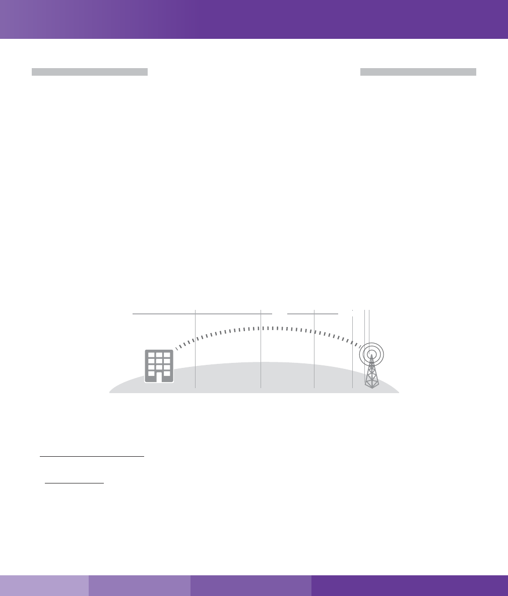
Finding Your Strongest Cellular Signal
To send and receive cell phone calls you need to have an adequate cellular signal. This usually means having to
be somewhat close to a cell phone tower. Your cellular signal is measured in decibels (dB), which represents the
power of the signal. Signal readings appear as a negative number, for example -85 dB. The stronger your signal
is the closer it gets to zero. As the illustration below shows a -50 dB signal reading is very strong while a signal
reading of -100 dB and above is very weak.
How to Determine Your dB Signal Reading
• Using an iPhone: Dial *3001#12345#*, a Field Test screen will appear press down on the home button for a
few seconds so your dB reading will appear in the upper left hand corner.
• Using an Android: Download the “Network Signal Info” within the Google Play store. Once installed, you will be
able to view your dB strength.
• Internet: Go to: www.speedtest.net to test your 3G and 4G data rates.
Signal Strength
Excellent
-50 dB
-60 dB
-70 dB
-80 dB
-90 dB
-100 dB
Good
Poor
Step 2. Install the Outdoor Antenna
The Force5 2.0 kit comes with one directional outside Yagi cellular antenna - however an outside omni antenna
may also be used.
A directional Yagi antenna works best when facing the direction of the nearest cellular tower being used by
your carrier
An omni antenna receives and sends signals in a 360º radius.
Before proceeding, please note:
• For both antenna options, mount the outside antenna in the location identied in step 1 and as high as
possible. Ensure that the mounting area has at least a 12-inch radius clear of obstructions and other radiating
elements.
Booster Installation
8
Booster Installation
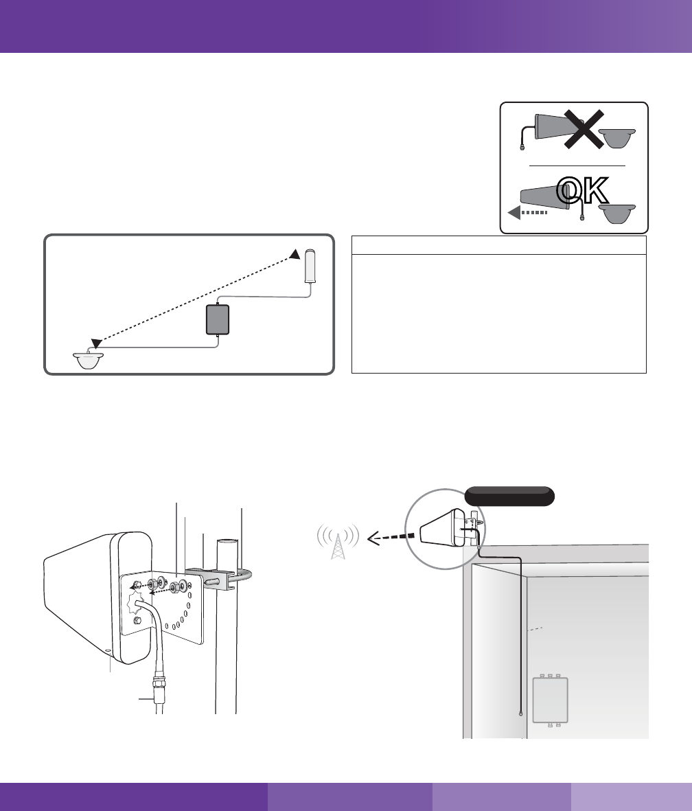
• For best performance, place the outside antenna at least 50 feet from the inside
antenna (see graphic “Antenna Separation”).
• Always orient directional antennas to point away from other system antennas
(see illustration, “Antenna Aiming”).
• Note that if the mounting area is prone to weak cellular signals or if dense
building materials partially block the signal, the booster will operate at its default
gain setting.
A
nt
e
nn
a
S
epar
a
ti
on
Required distance between
indoor & outdoor antennas
Outdoor/ Indoor Antenna Separation
A minimum of 50 ft. of separation between
the outdoor antenna and indoor antennas is
recommended for best performance.
Reducing antenna separation will reduce
the coverage provided by the booster and
generally, additional separation will provide better
performance.
Antenna Separation
Installing a Yagi Antenna
Before installing a Yagi, or directional antenna, note that the antenna should be mounted on a pole or pipe (not
provided), at the highest possible location and mounted horizontally, aimed in the direction of your nearest cell
tower. To nd the location of your carrier’s closest cell tower, go to www.antennasearch.com.
IMPORTANT: For boosters enhancing T-Mobile’s AWS frequencies, the FCC has stated for consumer signal boosters operating as a xed station in the 1710 - 1755
MHz uplink 2110 - 2155 downlink bands, the users or installation manual must contain the 30 foot height restriction requirements per FCC 27.50(d)(4).
OK
Antenna Aiming
Outdoor Yagi
Planned
booster
location
Outdoor
Cable
SC-400
Outside Antenna Assembly
Nut
Washer U-bolt
Bracket
Drip Hole
RG6 Cable
SureCall | 48346 Milmont Drive, Fremont CA 94538 | 1-888-365-6283 | support@surecall.com
9
SureCall | 48346 Milmont Drive, Fremont CA 94538 | 1-888-365-6283 | support@surecall.com
Booster Installation
Outdoor Omni
Planned
booster
location
Outdoor
Cable
Outdoor Antenna Surface Mount
Nuts &
Washers
L-Bracket
Cable
Anchors /
Sleeves
Screws
Ensure that the mounting area has at least a 12-inch radius clear of obstructions and other radiating elements and
orient the antenna with the drip hole at the bottom.
Once you have identied your install location, assemble the u-bolt, bracket, nuts and washers onto a pole or pipe
(not provided) as shown in the illustration. Keep the connections loose enough to allow the antenna to rotate until
the optimum direction is found.
Once the outside antenna is secured to a pipe or pole, connect antenna to cable connector of end of the 30 ft.
length of cable and run along route to planned location of your booster.
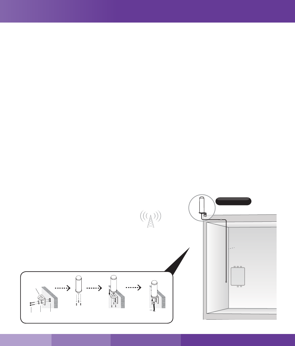
Installing an Optional Omni Antenna
The omni antenna is omni-directional, which receives and sends signals in a 360º radius. The provided hardware
allow for either a surface mount or pole-mount. The antenna should be mounted in an upright position. See
illustration.
Note: Do not collocate antennas or operate the outdoor antenna with any other antenna or signal booster.
Mount antenna to a vertical surface:
1. Using vertical plate of bracket, mark position of desired placement. The omni antenna should be mounted in
an upright position (See illustration)
2. Unscrew nut from end of stucco screw and remove it along with lock washer and regular washer.
3. Place vertical plate into desired location and tap the screws, head rst, along with sleeve, into stucco 1/2 to
5/8 inches deep into place.
4. In this order, place washer, lock washer and nut
on each screw and tighten until secure. When
tightening screw, sleeve will expand to secure
plate.
5. Remove screws from antenna base and use to
secure antenna onto horizontal plate.
6. Connect antenna to cable connector of end of
the 30 ft. length of cable and run along route to
planned location of your booster.

10
Booster Installation
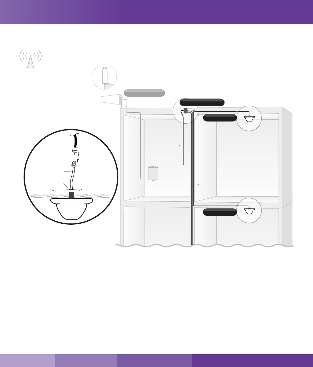
Step 3. Install the Indoor Antennas
Indoor antennas for the Force5 2.0 come with either four or two omni-directional domes. For either kit option,
mount on a ceiling in a central location where signal is needed.
The indoor dome multi-band plastic antenna is an omni-directional interior antenna that gathers and sends signals
from all sides. Range of antenna is dependent on three factors:
1. Physical obstructions
2. Power generated by booster
3. Signal level received by the outdoor antenna
4. Cable length
For Each Indoor Dome Antenna:
1. Drill a 20 mm diameter hole in the ceiling. The ceiling thickness should be 20 mm, maximum.
2. Unscrew xing nut from antenna. Place antenna cable through hole. Screw the xing nut back onto antenna
and cable on crawl space side of ceiling and fasten.
3. Connect antenna to cable connector of one of the two or four 75 ft. lengths of SC-400 cable and run along
route to planned location of your booster’s 4 way or 2-way splitter. Note: Should there be an excessive length
of unneeded cable, optional cable crimpers have been provided in order to shorten the cable.
4. Tighten xing nut to secure antenna (do not over-tighten).
5. Once all indoor antennas and cables are in place, connect cable runs from indoor antennas to the 4-way or
2-way splitter ports.
6. Connect the provided 20 ft. of SC-400 cable to the remaining end of the splitter and route cable to the
planned location of your booster.
Note: Be sure to provide the minimum 50 ft. of separation from outdoor antenna (see table on page 8).
Important:
• Storage and transportation: Store and place in non-extreme room-temperature and dry environment
• This antenna should not be used near open re or ame.
SureCall | 48346 Milmont Drive, Fremont CA 94538 | 1-888-365-6283 | support@surecall.com
11
SureCall | 48346 Milmont Drive, Fremont CA 94538 | 1-888-365-6283 | support@surecall.com
Booster Installation
Yagi
Omni
Outdoor Antenna
Outdoor
Cable
4-Way / 2-Way Splitter
Indoor Dome
Indoor Dome
Planned
booster
location Indoor
Cables
(75 ft.)
Indoor
Cable
(20 ft.)
RF CABLE
THREADED MOUNT
CEILING PLASTIC NUT
SC-400
INDOOR
CABLE
12
Booster Installation
Step 4. Install the Signal Booster
When placing the booster, select a location close to a working AC outlet. Do not expose the signal booster to
excessive heat, direct sunlight, moisture, and airtight enclosures.
1. Mount 24 inch x 24 inch, 3⁄4 inch thick sheet of plywood on top of sheetrock into wall studs where the booster
is to be placed. Plywood should be ush against wall. Once mounted, screw the booster to the plywood
sheet. The top side of the booster with the lights and DIP switches should be facing away from the wall and
plainly visible standing near the booster.
2. Connect the outdoor antenna cable to the signal booster connector port marked OUTSIDE and tighten the
connection.
3. Connect the cable coming from the indoor antennas’ 4-way or 2-way splitter to the booster port marked
INSIDE (see page 13) and tighten the connection.
4. Connect the AC power cord to the signal booster.
5. Connect the plug on the other end of
the 110V AC power outlet.
6. Turn the booster’s power switch on.
Once the booster is powered on:
• The green Power light should
illuminate.
• The band lights will ash red and
yellow for approximately 10 seconds.
Note: If the Power LED does not turn ON or the Alert LEDs continue to ash, (see “Troubleshooting” on page 17).This booster is rated for 5-20V input voltage. DO NOT
use the booster with a higher voltage power supply. This can damage the booster, cause personal injury and void your warranty.
Indoor Cables
(75 ft.)
Outdoor
Cable
(30 ft.)
Indoor
Cable
(20 ft.)
Splitter
Booster
Power Supply
Indoor Dome
Indoor Dome
Omni
Outdoor Antenna
Yagi
SureCall | 48346 Milmont Drive, Fremont CA 94538 | 1-888-365-6283 | support@surecall.com
13
SureCall | 48346 Milmont Drive, Fremont CA 94538 | 1-888-365-6283 | support@surecall.com
Booster Controls
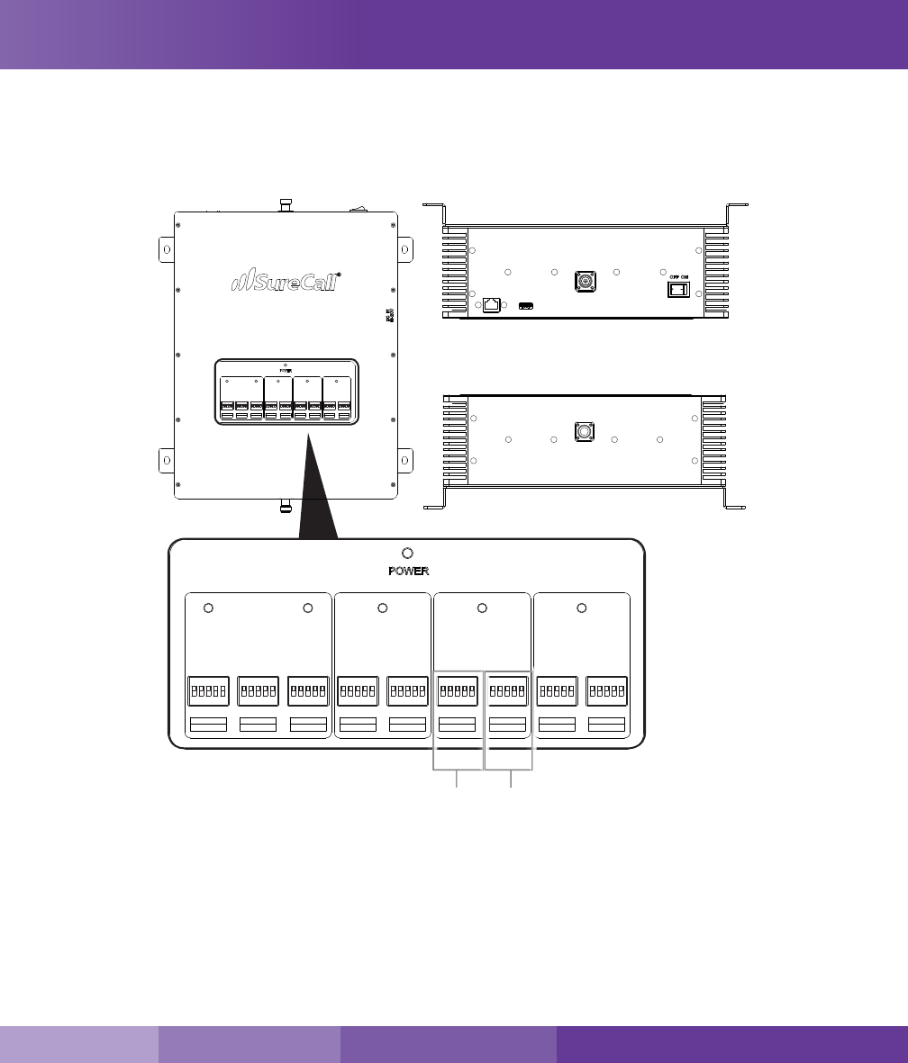
Booster Conguration
The Force5 2.0 has 9 DIP switches and the frequency bands they utilize for attenuation. Below the image is a
general attenuation guide.
DIP Switches and Lights
By default, your booster ships with all DIP switches turned OFF to provide maximum gain in all channels. This
should always be your starting point whenever installing or reinstalling the booster. When the booster is turned on,
the band lights will ash red and yellow for approximately 10 seconds.
ON/OFF Top View
USB
INSIDE
Network
Bottom View
OUTSIDE
LTE-A LTE-V CELLULAR AWS
AWS-DLAWS-ULLTE-V-DLLTE-A-UL LTE-DL
CELLULAR-UL CELLULAR-DL
1 2 4 8 16
ON
1 2 3 4 5
1 2 4 8 16
ON
1 2 3 4 5
1 2 4 8 16
ON
1 2 3 4 5
1 2 4 8 16
ON
1 2 3 4 5
1 2 4 8 16
ON
1 2 3 4 5
1 2 4 8 16
ON
1 2 3 4 5
1 2 4 8 16
ON
1 2 3 4 5
PCS
PCS-DLPCS-UL
1 2 4 8 16
ON
1 2 3 4 5
1 2 4 8 16
ON
1 2 3 4 5
UPLINK DOWNLINK
Booster DIP Switches
ON/OFF
Top View
USB
INSIDE
Network
Bottom View
OUTSIDE
LTE-A LTE-V CELLULAR AWS
AWS-DLAWS-ULLTE-V-DLLTE-A-UL LTE-DL
CELLULAR-UL CELLULAR-DL
1 2 4 8 16
ON
1 2 3 4 5
1 2 4 8 16
ON
1 2 3 4 5
1 2 4 8 16
ON
1 2 3 4 5
1 2 4 8 16
ON
1 2 3 4 5
1 2 4 8 16
ON
1 2 3 4 5
1 2 4 8 16
ON
1 2 3 4 5
1 2 4 8 16
ON
1 2 3 4 5
PCS
PCS-DLPCS-UL
1 2 4 8 16
ON
1 2 3 4 5
1 2 4 8 16
ON
1 2 3 4 5
14
Booster Controls
1. AWS-UL (2100 MHz) DIP switches control AWS uplink (switch 1-5)
2. AWS-DL (2100 MHz) DIP switches control AWS downlink (switch 1-5)
3. PCS-UL (1900 MHz) DIP switches control PCS uplink (switch 1-5)
4. PCS-DL (1900 MHz) DIP switches control PCS downlink (switch 1-5)
5. LTE-UL AT&T (707 MHz) DIP switches control LTE uplink (switch 1-5)
6. LTE-DL (728-757 MHz) DIP switches control LTE downlink (switch 1-5)
7. LTE-UL Verizon (781 MHz) DIP switches control LTE uplink (switch 1-5)
8. CELLULAR-UL (800 MHz) DIP switches control Cellular uplink (switch 1-5)
9. CELLULAR-DL (800 MHz) DIP switches control Cellular downlink (switch 1-5)
Switch 1 (1 dB) + Switch 2 (2 dB) = 3 dB attenuation
Switch 1 (1 dB) + Switch 2 (2 dB) + Switch 3 (4 dB) = 7 dB attenuation
Switch 1 (1 dB) + Switch 2 (2 dB) + Switch 3 (4 dB) + Switch 4 (8 dB) = 1 5 dB attenuation
Switch 1 (1 dB) + Switch 2 (2 dB) + Switch 3 (4 dB) + Switch 4 (8 dB) + Switch 5 (16 dB) = 31 dB attenuation
Adjusting Booster Cellular Attenuation
By default, all switches are turned OFF, meaning all frequency bands are operating at full gain.
• Turning a switch OFF increases booster gain for the selected
channel.
• Turning a switch ON adds attenuation (reduced amplication)
for the selected channel.
Switches should remain in the OFF position unless red
ashing lights occur for a channel or channels. Red ashing
lights indicate that the system has detected oscillation for the
corresponding channel(s) and turn o if adjustments are not
made.
ATTENUATION: Reduced amplication
Keep in mind when adjusting the booster: Full power is not
always the best option. Your goal is to obtain a usable cellular
signal in as many areas of the building as possible. A successful
installation means that you can make calls without dropping and/or have a reliable data connection.
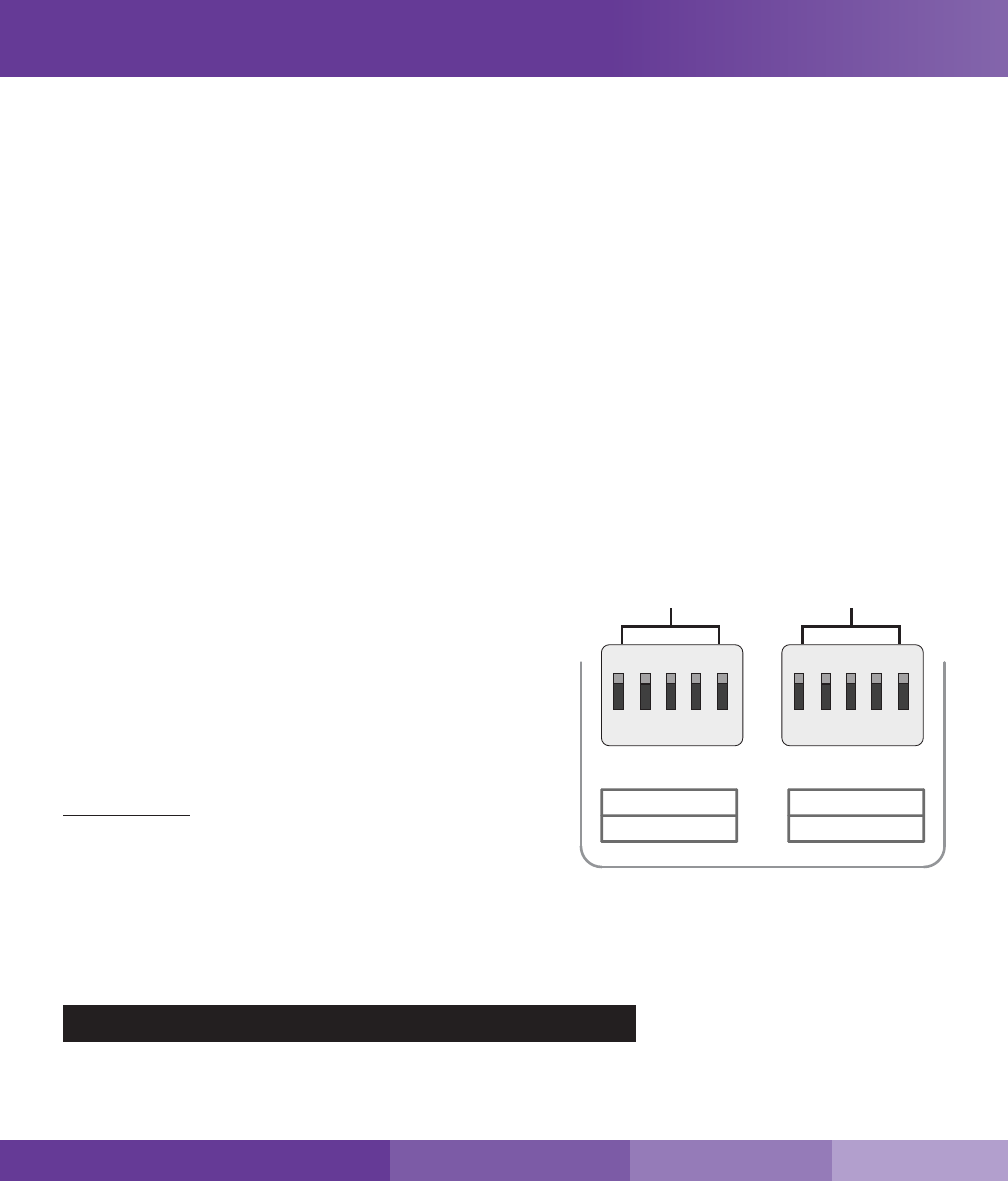
Each bank of DIP switches contain ve switches. From left to right, the DIP switches in each bank provide 1, 2, 4,
8, and 16 dB of attenuation (reduced amplication). These switches are cumulative, meaning that the total amount
of attenuation for a channel is equal to the combined dB of all ON DIP switches in the corresponding bank.
Switch 1 Switch 2 Switch 3 Switch 4 Switch 5
1 dB 2 dB 4 dB 8 dB 16 dB
1 2 4 8 16
DOWNLINK
UPLINK
124 8 16
1 2
3
4 5
PCS-DLPCS-UL
1 2 4 8 161 2 4 8 16
1 2 3 4 5
SureCall | 48346 Milmont Drive, Fremont CA 94538 | 1-888-365-6283 | support@surecall.com

15
SureCall | 48346 Milmont Drive, Fremont CA 94538 | 1-888-365-6283 | support@surecall.com
Booster Controls Booster Controls
Example:
• Turning all switches OFF = 0 dB attenuation (booster is at full gain).
• Turning ON Switch #1 in a bank = 1 dB attenuation (booster maximum gain is reduced by 1 dB).
• Turning ON Switches #1, 3, and 5 in a bank = 1+4+16 dB attenuation = 21 dB attenuation.
• In an 80 dB booster, this means the selected channel would be reduced to 59 dB (80 dB -21 dB).
• Turning ON all switches in a bank = 1+2+4+8+16 dB attenuation = 31 dB attenuation
In an 80 dB booster, that means that the selected channel would be reduced to 49 dB (80 dB-31 dB).
Testing
Once the booster is powered on and no Warning lights are illuminated, walk around the entire area to test the
voice and/or data signal. Rene the antenna locations and/or gain levels as needed, and then complete the
permanent installation once the system is working as desired.
Remember: Bars are not always a reliable measure of signal. The best way to conrm signal coverage is the ability to
place and hold a call.
16
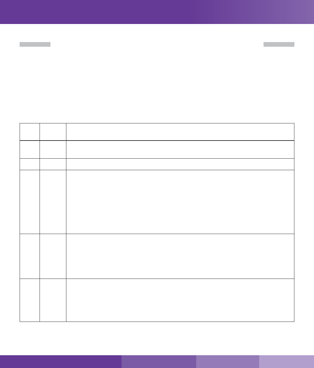
LED Indicators
Section 2: Booster Operation and Troubleshooting
Please note the following information:
• As highlighted in the table below, all of the following conditions indicate normal operation: lights o, ashing
yellow, or solid yellow.
• Only the presence of red LEDs indicate an unresolved issue.
• The booster gain switches should always be at maximum level unless the control light for a specic frequency
band is ashing red or ashing red-yellow. In either case, only reduce gain via switches if other recommended
actions do not resolve the issue.
• Avoid exceeding 25 dB of attenuation as this could cause aected frequency band to stop amplifying.
LE
D
Color
LED
Condition
Indication
Yellow
Solid
Indicates that the frequency band is not being used. After a period of time, if there’s no activity, that
band will go into sleep mode. Light is o while band is active. This is part of normal operation.
Yellow
Flashing
Indicates that the Automatic Gain Control (AGC) is self-adjusting. This is part of normal operation.
Red
Flashing
Indicates that the booster is receiving too much signal which could cause the aected frequency band to
turn o. If this happens:
1. For kits using an OMNI outside antenna, relocate the outside antenna to a location where the signal is
weaker.
2. For kits using a DIRECTIONAL outside antenna, turn the antenna in short increments away from the
signal source.
3. Add an inline attenuator to the cable coming into the outside port of the booster.
4. Though not desirable as amplication will not be optimum, lower the dB gain setting in small
increments until the light turns o or ashes yellow.
Red
Solid
The frequency band is o.
If a red light has been ashing for an extended time due to too much signal, that frequency band will display
a solid red light indicating that the circuitry for that frequency band has been turned o. If this happens:
First, power cycle the booster. If, after power cycling, you observe Red Flashing LEDs, follow the steps
outlined for Red Flashing condition until overpowering has been corrected.
Note: This may happen if attenuation greater than 25 dB has been made.
Red/
Yellow
Alternately
Flashing
Self-oscillation has been detected and to prevent it, one or more of the frequency bands have shut o. If this
happens:
First, try increasing the vertical/horizontal separation between the outside antenna and inside antennas. If
your booster kit uses two directional antennas (examples: outside Yagi antenna or inside panel antenna),
ensure that they are facing away from one another (see “Antenna Aiming” on page 8).
If condition continues, lower the dB gain setting in small increments until the light turns o or ashes yellow.
SureCall | 48346 Milmont Drive, Fremont CA 94538 | 1-888-365-6283 | support@surecall.com
17
SureCall | 48346 Milmont Drive, Fremont CA 94538 | 1-888-365-6283 | support@surecall.com
Troubleshooting
LED Indicators
Troubleshooting
In the event you encounter a problem, follow the suggestions below to resolve the issue.
Problem Resolution
Signal booster has no power Verify that the booster switch is turned on.
Connect the power supply to an alternate power source.
Verify that the power source is not controlled by a switch that has removed power
from the outlet.
If the POWER LED on the signal booster is OFF, return the power supply to SureCall.
Contact tech support to receive an RMA at:
1-888-365-6283 or support@surecall.com, or go to www.surecall.com 7:00 am –
5:00 pm PST, Monday – Friday to chat with a representative.
After completing installation, indoor
signal coverage has not improved
Check the installation of your outdoor antenna. Ensure that the mounting area is clear
of obstructions and other radiating elements.
Check the outdoor signal strength at the site the outdoor antenna (see instructions on
page 7).
For kits that use a directional Yagi antenna, verify that the antenna is properly aimed
in the direction of your carrier’s closest cell tower (see “Installing a Yagi Antenna” on
page 8).
Verify that all cable connections are tightly tted to the booster and antennas.
Remember: Bars are not always a reliable measure of signal. The best way to conrm
signal coverage is the ability to place and hold a call.
18
Sentry Conguration
Section 3: Built-in Sentry
For remote monitoring, your Force5 comes with Sentry, SureCall’s software that allows users to adjust the
attenuation to control:
• Over-Powering
• Oscillation
• Attenuation
Sentry Hardware Installation
Step 1: Connect the USB cable (provided) to the Sentry’s USB port then connect the other end of the USB cable
to the USB port on your computer. The USB is only needed for conguration and may be disconnected
once complete.
Step 2: Connect an Ethernet cable (not provided) to the booster's WAN port and connect the other end to your
router.
Sentry Software Installation
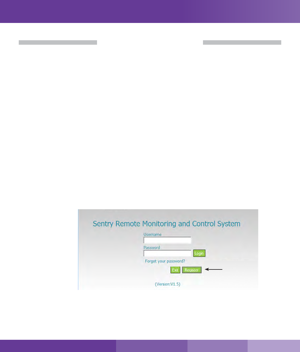
User Registration:
SureCall | 48346 Milmont Drive, Fremont CA 94538 | 1-888-365-6283 | support@surecall.com
19
SureCall | 48346 Milmont Drive, Fremont CA 94538 | 1-888-365-6283 | support@surecall.com
Sentry Conguration Sentry Conguration
Step 1: Download the software at
surecall.com/support/sentry
Step 2: Install the software on the computer that you will
be using for remote monitoring. Run as admin.
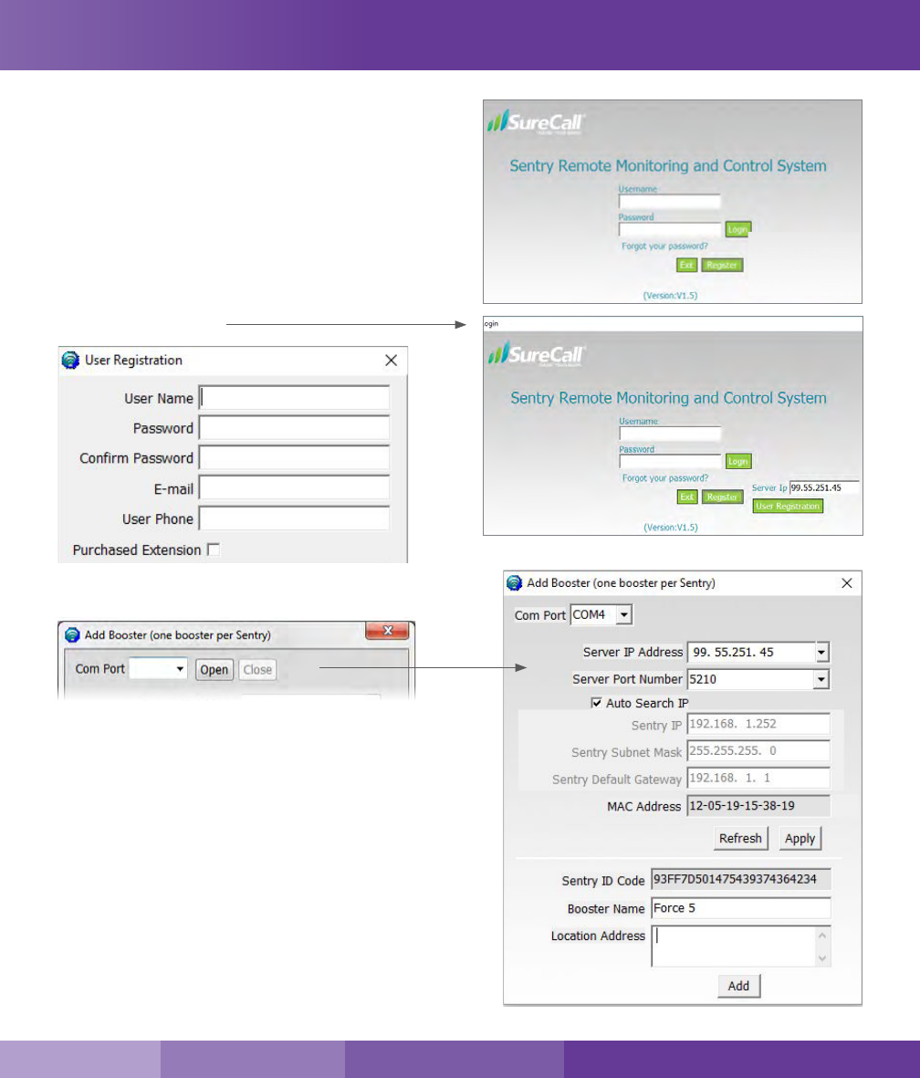
Step 3: Enter SureCall’s Server IP address, 99.55.251.45
in the Registration Window.
Step 4: Fill in the User Registration form and choose a
user name, password, email and user phone.
Once completed, click the Register button.
Step 5: Login to Sentry
Select Com Port and Open
» Once the correct port has been chosen, other elds
will autopopulate except for booster name and location
address
» Verify that the server IP address is 99.55.251.45. If not,
select the new IP address and click “Apply”
» Next, enter a Booster Name, a Location Address is
optional
» Once complete, you may click "Add" and close the
window
20
Sentry Conguration
Adding a Booster
When a booster is connected
to Sentry, it will automatically
identify the model of the
booster and show the
corresponding interface.
On the main interface screen,
select the booster located
in the left column, this will
automatically populate the
elds with the booster’s
parameters.
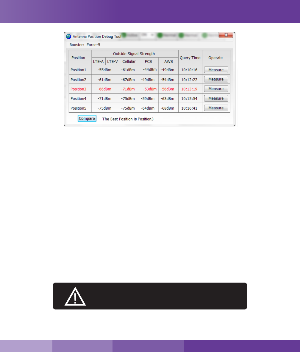
Using Optional Antenna
Placement Tool
This tool aids the installer in
locating the best location for an
outside antenna.
To test for the best location, the
booster and outside antenna
must be connected by coax
cable.
Place the antenna in a position you’d like to test and click on the measure button.
SureCall | 48346 Milmont Drive, Fremont CA 94538 | 1-888-365-6283 | support@surecall.com
21
SureCall | 48346 Milmont Drive, Fremont CA 94538 | 1-888-365-6283 | support@surecall.com
This tool will identify the optimum location for the outdoor antenna. The “Position” elds will automatically populate
with the dB measurement from various locations by clicking on the measure button at each possible location. You
can test up to 5 positions. Once you have entered all locations, click on the “Compare” button to nd the best
location. Keep in mind that a signal of less than -65 dB can over-power the booster. Aim for a range of -60 to
-80 dB. The signal strength can be adjusted to a weaker signal by:
• Moving the outside antenna to a dierent location
• Adding an inline attenuator to the cable connecting to the booster
• Lowering the dB gain with the DIP switches on the booster or through the Attenuation column in the Sentry
Congure Gain Settings
Attenuation:
If the “Over Power” alert is red, the signal coming into the booster from the cellular tower is too strong which will
shut down the aected band. There are three possible solutions:
1. Add an inline 5 dB or 10 dB attenuator (parts: SC-ATNR-5 and SC-ATNR-10) to the cable coming into the
booster.
2. Relocate the outdoor antenna to a location where the signal is weaker. Or, If using a Yagi outside antenna, turn
in small increments away from cell tower until Red alert is resolved.
3. Lower the dB gain in small increments on the Sentry booster dashboard under the Attenuation column until
the Over Power alert is resolved.
ATTENUATION THROUGH CLIENT SOFTWARE IS
CUMULATIVE WITH THAT OF DIP SWITCHES.
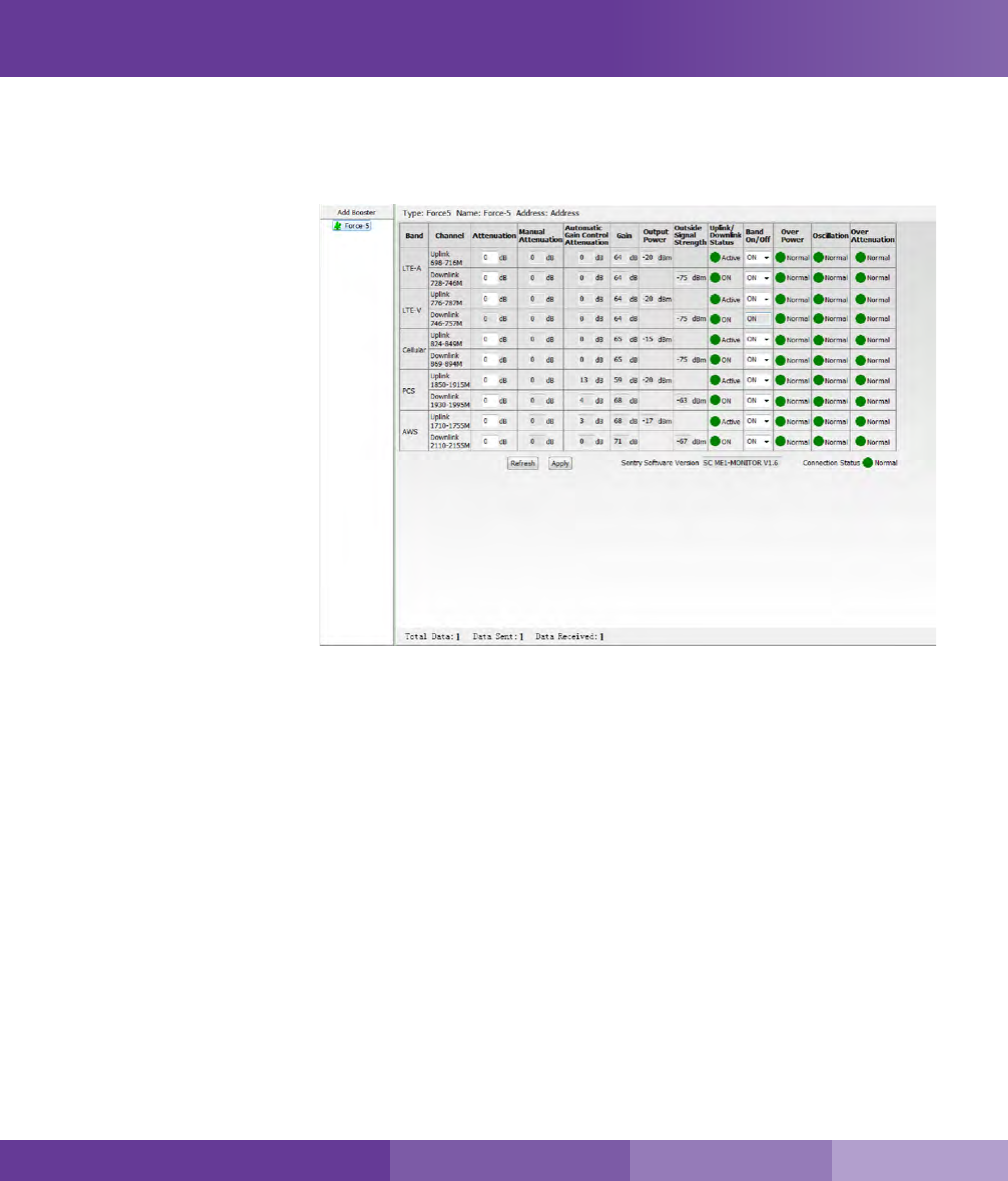
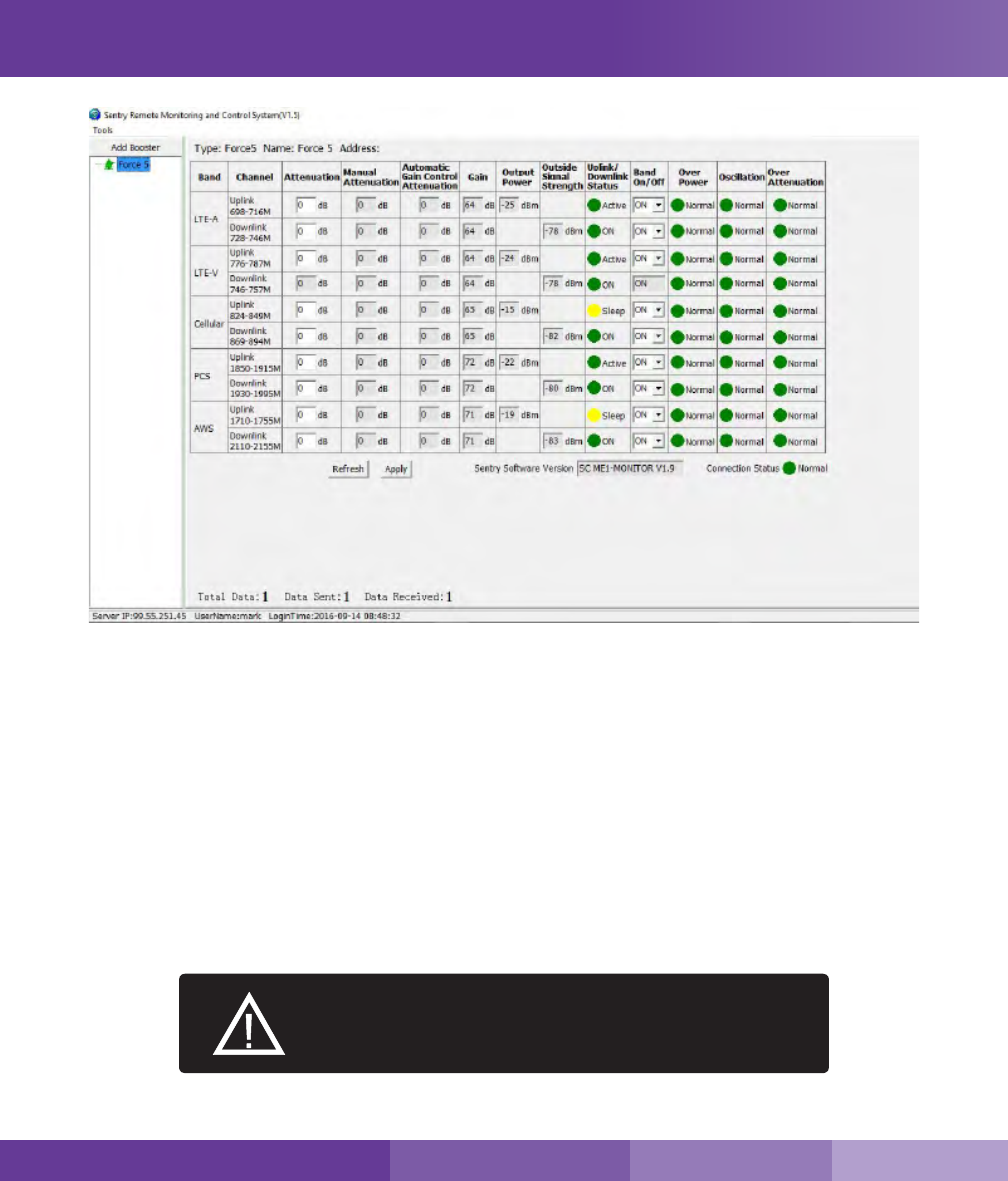
Sentry Operation
22
From the dashboard above you can manually adjust the attenuation dB to resolve problems with oscillation and
overpowering issues. You can also turn o individual bands.
Column Denitions:
Attenuation: Adjusts the amount of gain reduction.
Manual Attenuation: Indicates the reduced gain through the booster’s DIP switches.
Automatic Gain Control: Indicates when the booster is automatically reducing the gain due to a strong
outdoor signal or close indoor/outdoor antenna proximity.
Gain: Indicates the current gain on the amplier.
Output Power: Indicates the power output level of the booster in dBm.
Uplink/Downlink Status: Indicates whether a band is asleep, turned on or turned o.
ATTENUATION CAN BE LOWERED TO A MAXIMUM OF 30
OR 31 DB, DEPENDING ON THE BOOSTER MODEL AND A
MAX OF 25 DB THROUGH SENTRY SOFTWARE.
Sentry Operation
Sentry Dashboard
SureCall | 48346 Milmont Drive, Fremont CA 94538 | 1-888-365-6283 | support@surecall.com
23
SureCall | 48346 Milmont Drive, Fremont CA 94538 | 1-888-365-6283 | support@surecall.com
Email Alerts
Email alerts will be sent in the event of booster overpowering, over-attenuation, or if oscillation is detected.
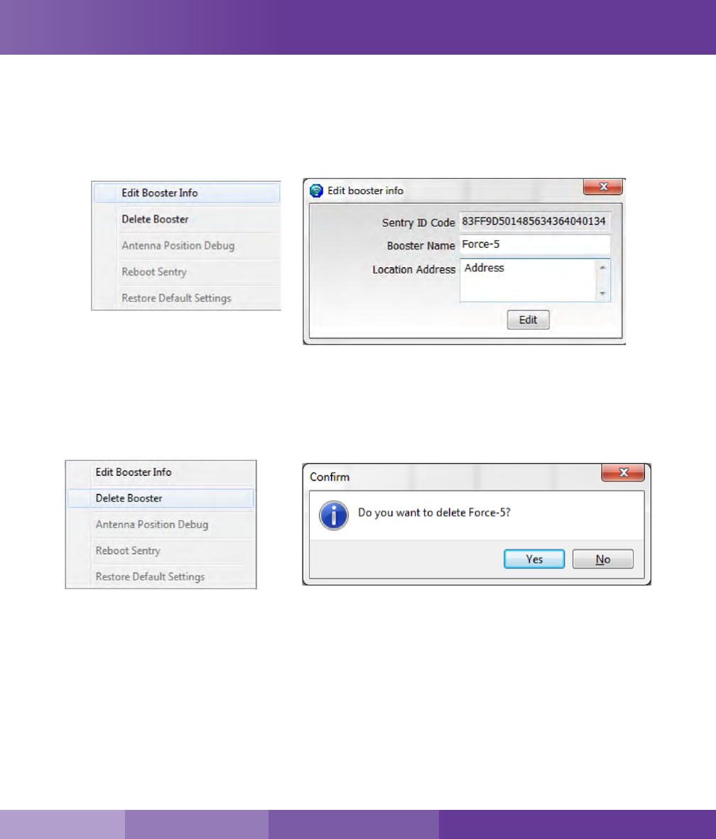
Changing your Booster Information
If you wish to change your Booster information, click on Edit Booster Info within the left hand navigation
Deleting a Booster
If you wish to delete a booster in order to add a new one, right click on the specic booster in the left hand
navigational eld rst, then click on “Delete Booster” within the navigation window, click on and conrm the
deletion. See below.
Sentry Operation
24
Forget your Password?
On the login page, type in the email address that you
entered when you rst registered and click on “Forgot
your Password”. Your password will be emailed to you.
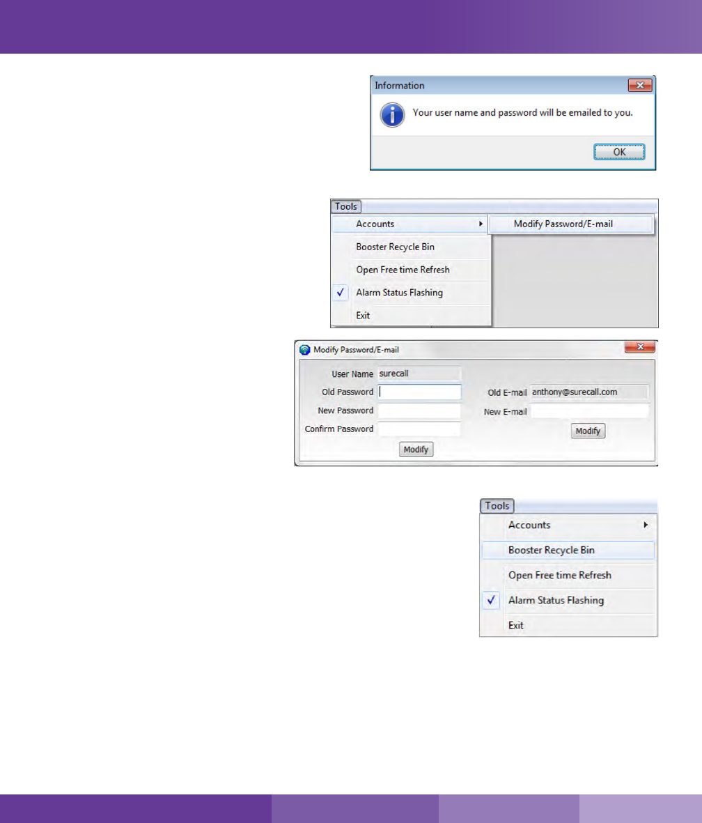
Modifying your password:
To change your password, choose Tools in the
top navigation and select the Accounts menu and
select Modify Password/E-mail from the drop-
down menu.
Enter the Old Password, choose a new password,
conrm the new password and click on modify.
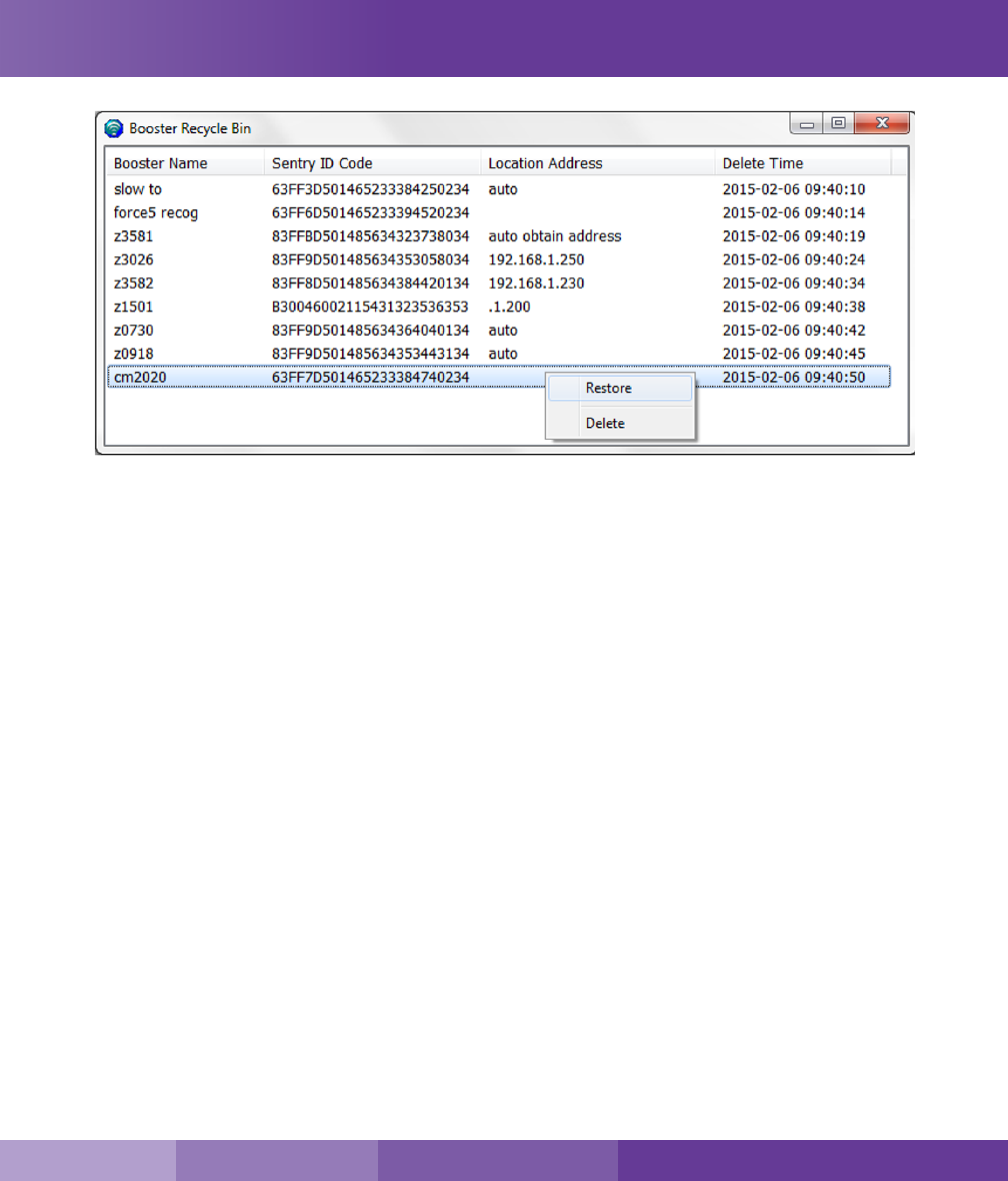
Archiving Booster Information
To temporarily change boosters, choose Tools in the top navigation and select
“Booster Recycle Bin”. Information for this booster will be saved. Should you
like to switch back to this booster or delete it, go back to “Booster Recycle
Bin” where you will be given the option to restore or delete the booster.
Sentry Operation
SureCall | 48346 Milmont Drive, Fremont CA 94538 | 1-888-365-6283 | support@surecall.com
25
SureCall | 48346 Milmont Drive, Fremont CA 94538 | 1-888-365-6283 | support@surecall.com
Sentry Operation
26
Specications Kitting Information
SureCall | 48346 Milmont Drive, Fremont CA 94538 | 1-888-365-6283 | support@surecall.com
Section 4: Specications
Force5 2.0 Specications
Cellular Uplink Frequency Range (MHz): 698–716 / 776–787 / 824–849 / 1850–1915 / 1710–1755 (G Block Included)
Cellular Downlink Frequency Range (MHz): 728–746 / 746–757 / 869–894 / 1930–1995 / 2110–2155 (G Block Included)
Supported Cellular Standards: CDMA, WCDMA, GSM, EDGE, HSPA+, EVDO, LTE and all cellular standards
Input Impedance: 50 Ω
Maximum Gain: Cellular 72 dB
Noise Figure: 5 dB
VSWR: ≤2.0
AC Input / Output: Input AC 110 V, 60 Hz / Output DC 15-20 V
Maximum Output Power: 1 Watt EIRP
Cable: SC-400
RF Connectors: N Female
Power Consumption: <65W
Operation Temperature: -4º F to +158º F
Dimensions: 14.5 x 11 x 3.5 inches
Weight: 19.5 lbs
FCC: RSNFORCE5S
27
SureCall | 48346 Milmont Drive, Fremont CA 94538 | 1-888-365-6283 | support@surecall.com
Specications Kitting Information
Important: Unauthorized antenna cables and/or coupling devices may not be used. Changes or modications not expressly approved by
the Surecall could void the user’s authority to operate the equipment.
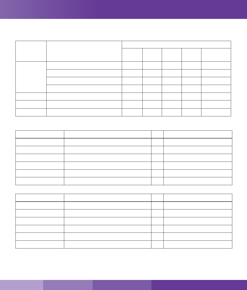
Kitting Information
Component Product Number / Description / Note Gain / Loss
LTE-A LTE-V Cellular
800 MHz
PCS
1900 MHz
AWS
1700 / 2100 MHz
Outdoor
Antenna
SC-288W: Omni 3 dBi 3 dBi 3 dBi 4 dBi 4 / 4 dBi
SC-288W-L: Omni 5 dBi 5 dBi 6 dBi 8 dBi 8 / 8 dBi
SC-230W: Yagi 10 dBi 10 dBi 10 dBi 10 dBi 10 / 10 dBi
SC-510W 5 dBi 5 dBi 7 dBi 10 dBi 10 / 10 dBi
Outdoor Cable SC-400-30 NN, 30 ft, — Use 30 ft or longer 2.05 dB 2.05 dB 2.12 dB 2.83 dB 2.68 / 2.98 dB
Indoor Cable SC-400-75 NN, 75 ft, — Use 75 ft or longer 4.22 dB 4.22 dB 4.41 dB 6.17 dB 5.8 / 6.54 dB
Indoor Antenna SC-222W: Dome 3 dBi 3 dBi 3 dBi 6 dBi 6 / 6 dBi
The Force5 2.0 booster is suitable for use with all equivalent and lower gain antennas and cables
Included in kit 1
Component Product Qty Notes
Outdoor Antenna SC-230W: Yagi 1
Outdoor Cable SC-400-30 NN, 30 ft 1 Use 30 ft or longer
Indoor Cable SC-400-20 NN, 20 ft 1 Use 20 ft or longer
Splitter SC-WS-4 1
Indoor Cables (to Antennas) SC-400-75 NN, 75 ft, 4 Use 75 ft or longer
Indoor Antennas SC-222W: Dome 4
Included in kit 2
Component Product Qty Notes
Outdoor Antenna SC-230W: Yagi 1
Outdoor Cable SC-400-30 NN, 30 ft 1 Use 30 ft or longer
Indoor Cable SC-400-20 NN, 20 ft, 1 Use 20 ft. or longer
Splitter SC-WS-2 1
Indoor Cables (to Antennas) SC-400-75 NN, 75 ft, 2 Use 75 ft or longer
Indoor Antennas SC-222W: Dome 2
*This Force5 2.0 booster is suitable for use with all equivalent and lower gain antennas and cables.

28
FCC and Safety
SureCall | 48346 Milmont Drive, Fremont CA 94538 | 1-888-365-6283 | support@surecall.com
Section 5: FCC & Safety Information
SureCall has made a good faith eort to ensure the accuracy of the information in this document and disclaims the implied warranties of
merchantability and tness for a particular purpose and makes no express warranties, except as may be stated in its written agreement with and
for its customers. SureCall shall not be held liable to anyone for any indirect, special or consequential damages due to omissions or errors. The
information and specications in this document are subject to change without notice.
© 2017. All Rights Reserved. All trademarks and registered trademarks are the property of their respective owners.
48346 Milmont Drive
Fremont, California 94538, USA
888.365.6283
www.surecall.com
Important: Before installing your booster you need to register it with your carrier. You can do so online at the following urls:
Verizon: http://www.verizonwireless.com/wcms/consumer/register-signal-booster.html
AT&T: https://securec45.securewebsession.com/attsignalbooster.com/
T-Mobile: https://support.t-mobile.com/docs/DOC-9827
Sprint: https://www.sprint.com/legal/fcc_boosters.html
U.S. Cellular: http://www.uscellular.com/uscellular/support/fcc-booster-registration.jsp
FCC Information:
This is a CONSUMER device.
BEFORE USE, you MUST REGISTER THIS DEVICE with your wireless provider and have your provider’s consent. Most wireless providers consent to the
use of signal boosters. Some providers may not consent to the use of this device on their network. If you are unsure, contact your provider.
You MUST operate this device with approved antennas and cables as specied by the manufacturer. Antennas MUST be installed at least 20 cm (8 inches)
from any person. You MUST cease operating this device immediately if requested by the FCC or a licensed wireless service provider.
This device may be operated ONLY in a xed location for in-building use.
WARNING: E911 location information may not be provided or may be inaccurate for calls served BY USING THIS DEVICE.
Note: This equipment has been tested and found to comply with the limits for a Class B digital device, pursuant to part 15 of the FCC Rules. These limits
are designed to provide reasonable protection against harmful interference in a residential installation. This equipment generates, uses and can radiate radio
frequency energy and, if not installed and used in accordance with the instructions, may cause harmful interference to radio communications. However,
there is no guarantee that interference will not occur in a particular installation. If this equipment does cause harmful interference to radio or television
reception, which can be determined by turning the equipment o and on, the user is encouraged to try to correct the interference by one or more of the
following measures:
• Reorient or relocate the receiving antenna
• Increase the separation between the equipment and receiver.
• Connect the equipment into an outlet on a circuit dierent from that to which the receiver is connected
• Consult the dealer or an experienced radio/TV technician for help.
15.19 This device complies with Part 15 of the FCC Rules. Operation is subject to the following two conditions:
(1) this device may not cause harmful interference, and (2) this device must accept any interference received, including interference that may cause
undesired operation.

29
SureCall | 48346 Milmont Drive, Fremont CA 94538 | 1-888-365-6283 | support@surecall.com
Warranty
Section 6: Three-Year Product Warranty
Register at www.SureCall.com
SureCall warrants its products for three years from the date of purchase against defects in workmanship and/or materials. Specications are
subject to change. The three-year warranty only applies to products meeting the latest FCC Certication Guidelines stated on 2/20/2013 and
going into eect April 30, 2014. A two-year warranty applies to any products manufactured before May 1, 2014.
Products returned by customers must be in their original, un-modied condition, shipped in the original or protective packaging with proof-
of-purchase documentation enclosed, and a Return Merchandise Authorization (RMA) number printed clearly on the outside of the shipping
container.
Buyers may obtain an RMA number for warranty returns by calling the SureCall Return Department toll-free at 1-888-365-6283. Any returns
received by SureCall without an RMA number clearly printed on the outside of the shipping container will be returned to sender. In order to receive
full credit for signal boosters, all accessories originally included in the signal booster box must be returned with the signal booster. (The Buyer
does not need to include accessories sold in addition to the signal booster, such as antennas or cables.)
This warranty does not apply to any product determined by SureCall to have been subjected to misuse, abuse, neglect, or mishandling that alters
or damages the product’s physical or electronic properties.
SureCall warrants to the Buyer that each of its products, when shipped, will be free from defects in material and workmanship, and will perform
in full accordance with applicable specications. The limit of liability under this warranty is, at SureCall’s option, to repair or replace any product
or part thereof which was purchased up to THREE YEARS after May 1, 2014 or TWO YEARS for products purchased before May 1, 2014, as
determined by examination by SureCall, prove defective in material and/or workmanship. Warranty returns must rst be authorized in writing by
SureCall. Disassembly of any SureCall product by anyone other than an authorized representative of SureCall voids this warranty in its entirety.
SureCall reserves the right to make changes in any of its products without incurring any obligation to make the same changes on previously
delivered products.
As a condition to the warranties provided for herein, the Buyer will prepay the shipping charges for all products returned to SureCall for repair, and
SureCall will pay the return shipping with the exception of products returned from outside the United States, in which case the Buyer will pay the
shipping charges.
The Buyer will pay the cost of inspecting and testing any goods returned under the warranty or otherwise, which are found to meet the applicable
specications or which are not defective or not covered by this warranty.
Products sold by SureCall shall not be considered defective or non-conforming to the Buyer’s order if they satisfactorily fulll the performance
requirements that were published in the product specication literature, or in accordance with samples provided by SureCall. This warranty shall
not apply to any products or parts thereof which have been subject to accident, negligence, alteration, abuse, or misuse. SureCall makes no
warranty whatsoever in respect to accessories or parts not supplied by it.
Limitations of Warranty, Damages and Liability:
EXCEPT AS EXPRESSLY SET FORTH HEREIN, THERE ARE NO WARRANTIES, CONDITIONS, GUARANTEES, OR REPRESENTATIONS
AS TO MERCHANTABILITY, FITNESS FOR A PARTICULAR PURPOSE, OR OTHER WARRANTIES, CONDITIONS, GUARANTEES, OR
REPRESENTATIONS, WHETHER EXPRESSED OR IMPLIED, IN LAW OR IN FACT, ORAL OR IN WRITING.
SURECALL AGGREGATE LIABILITY IN DAMAGES OR OTHERWISE SHALL NOT EXCEED THE PAYMENT, IF ANY, RECEIVED BY CELLPHONE-
MATE, INC. FOR THE UNIT OF PRODUCT OR SERVICE FURNISHED OR TO BE FURNISHED, AS THE CASE MAY BE, WHICH IS THE
SUBJECT OF CLAIM OR DISPUTE. IN NO EVENT SHALL SURECALL BE LIABLE FOR INCIDENTAL, CONSEQUENTIAL, OR SPECIAL
DAMAGES, HOWSOEVER CAUSED.
All matters regarding this warranty shall be interpreted in accordance with the laws of the State of California, and any controversy that cannot
be settled directly shall be settled by arbitration in California in accordance with the rules then prevailing of the American Arbitration Association,
and judgment upon the award rendered may be entered in any court having jurisdiction thereof. If one or more provisions provided herein are
held to be invalid or unenforceable under applicable law, then such provision shall be ineective and excluded to the extent of such invalidity or
unenforceability without aecting in any way the remaining provisions hereof.

FCC 27.50(d)(4) Statement: Fixed, mobile and portable (hand-held) stations operating in the 1720-1755 MHz band are limited 1 Watt EIRP. Fixed
stations operating in this band are limited to a maximum antenna height of 10 meters above ground. Mobile and portable stations operating in this
band must employ a means for limiting power to the minimum necessary for successful communications.
48346 Milmont Drive
Fremont, California 94538, USA
888.365.6283
www.surecall.com