Cellphone Mate SureCall FUSION-5 Five Band In Building Signal Booster User Manual
Cellphone-Mate Inc. dba SureCall Five Band In Building Signal Booster Users Manual
UserManual.wiki
>
Cellphone Mate SureCall
>
FUSION-5 User Manual
>
Users Manual
Contents
1.
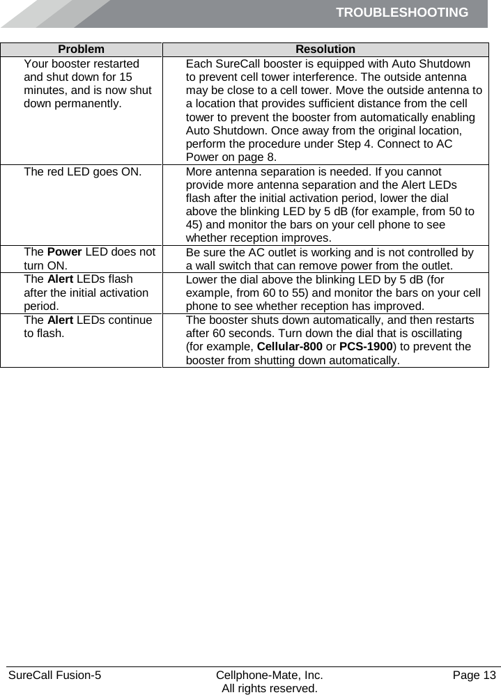
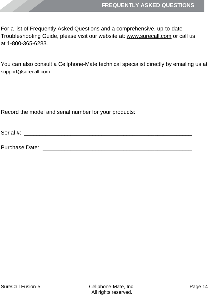
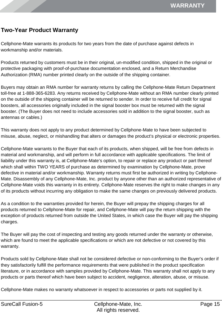
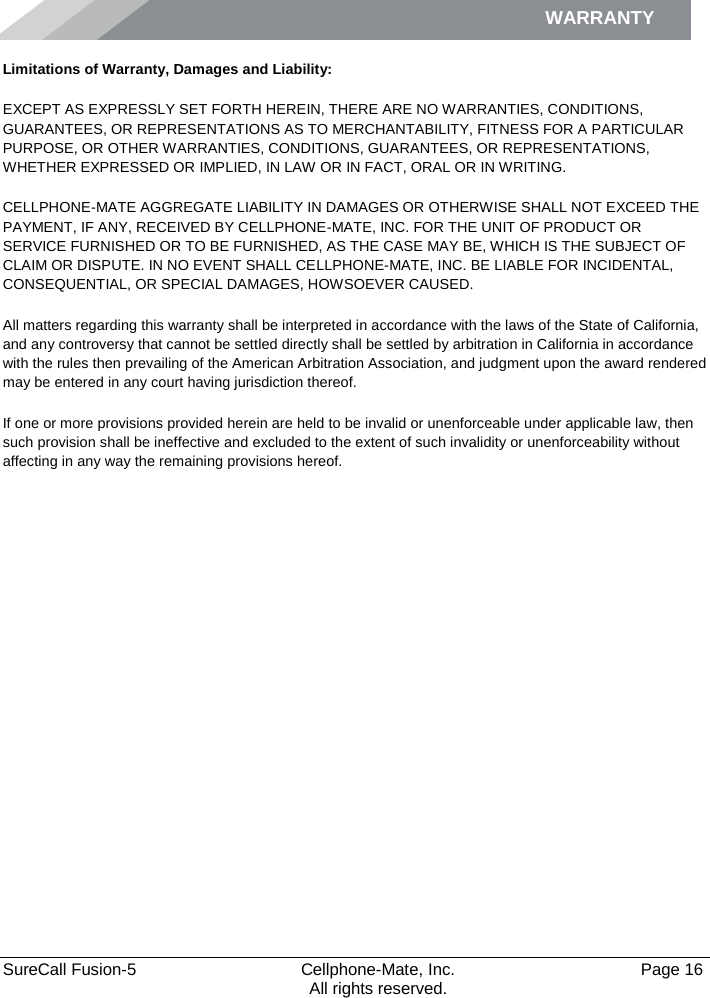
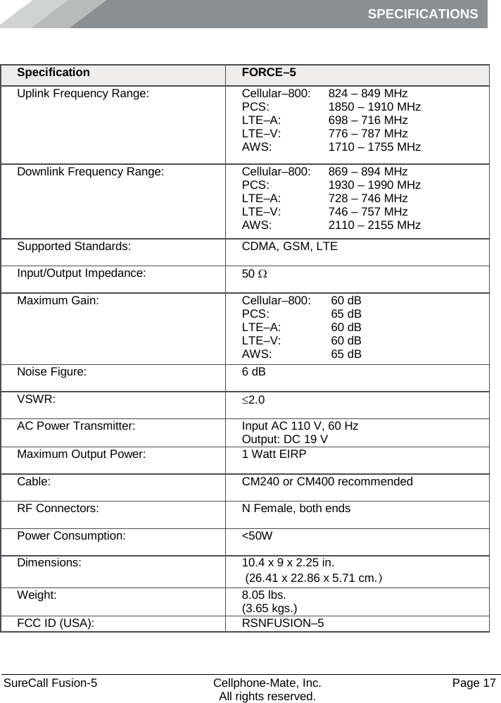
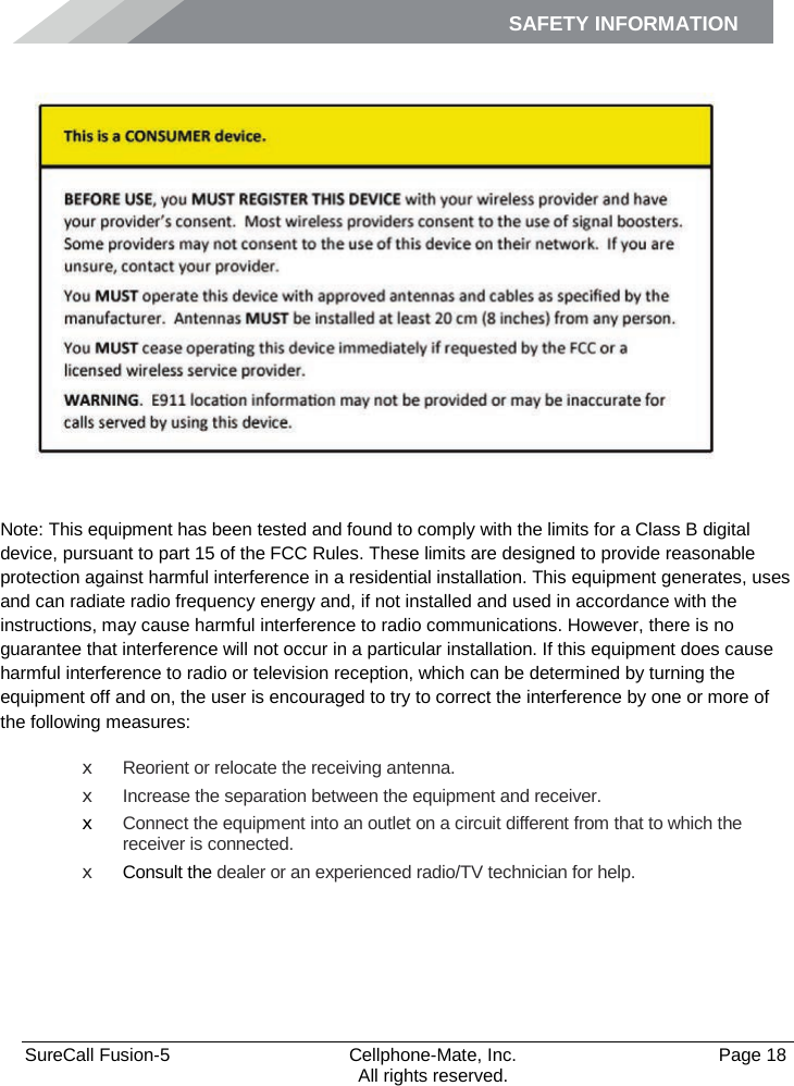
Users Manual
2.
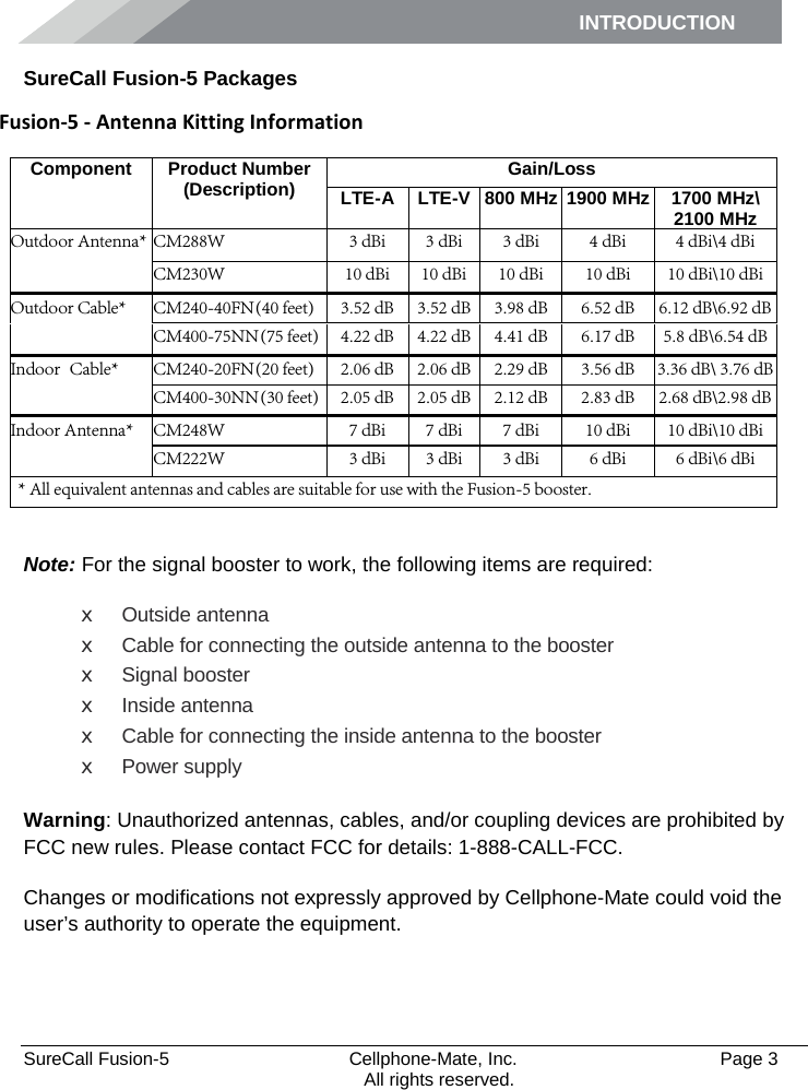
Antenna Kitting Info
Users Manual
Navigation menu
Upload a User Manual
Namespaces
Wiki Guide
HTML
PDF
Info
Views
User Manual
Discussion / Help
Navigation