Centrak 2X73Y Temperature Sensir Tag IT-735P User Manual InTouchCareUserManual
Centrak, Inc. Temperature Sensir Tag IT-735P InTouchCareUserManual
Centrak >
User Manual
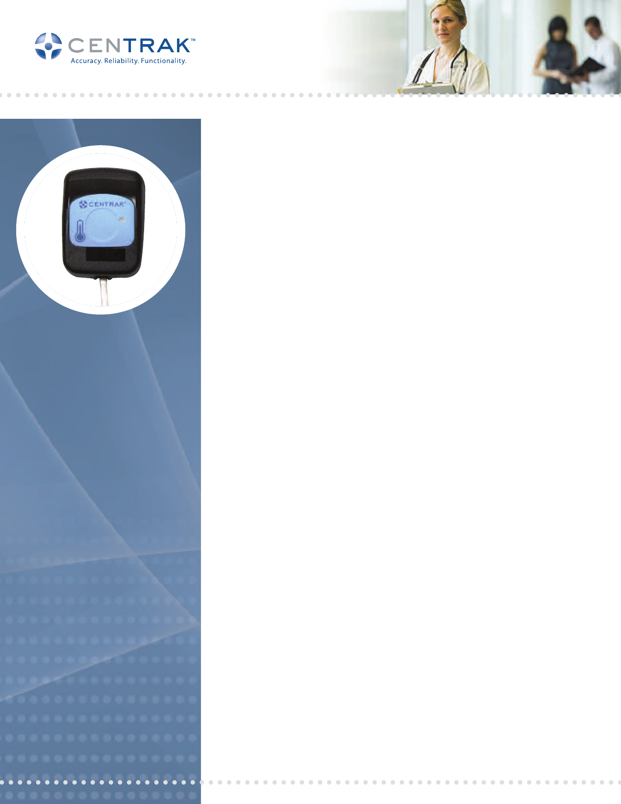
CENTRAK PROBE-BASED TEMPERATURE
SENSORTAGRIT-735P
Hospitals have a critical need for wireless monitoring of environmental fluctuations. They
require reliable real time monitoring and alerting capabilities as well as comprehensive
records of sensor data for reporting and analysis purposes. CenTrak’s advanced
temperature sensing technology was developed to meet those needs.
The IT-735 is a probe-based temperature sensing tag that has the ability to monitor a wide
range of temperatures, from cryogenic (-200C) to room temperature (+50C), reliably and
accurately with customizable reporting rates down to 12 seconds at 0.75C accuracy. It is
available for use with three specific temperature range probes : -20C to +50C (ITA-781),
-100 to -20C (ITA-782), and -200 to -100C (ITA-783)
The IT¬735 Tag creates a cost effective way to improve patient care as well as provide
automated and detailed reports for any time period. In conjunction with the CenTrak RTLS
this single Tag can be used to track, locate, identify and ensure correct temperature levels
and can generate alerts via email/SMS when the temperature goes above or below set
parameters. The system can also provide temperature logs which eliminate human error
and the cost of manual temperature documentation.
Tags send temperature readings in intervals specified by the user (e.g., every one minute). The
battery powered tags will even continue to monitor temperature and send a local alert in the
event of a power outage. Tags provide an automated and accurate solution that improves
regulatory compliance and saves time so that staff can focus on patient care and safety.
About CenTrak Technology
CenTrak’s core RTLS differs from legacy technologies in its use of a patented combination of
second-generation infrared (Gen2IR™) and active RFID technology called DualTrak. Battery
powered Monitors transmit a unique room number using Gen2IR which is received by any tag
in that room. The tag communicates the room number and its own unique ID via RF to the
CenTrak Location Server using a hospital’s existing wired or Wi-Fi network, where it can be
accessed in real-time by hospital personnel and integrated with third party solution providers.
Like light, Gen2IR will not pass through walls and does not suffer from traditional infrared
line-of-sight limitations. Therefore, when a tag reads a room number, there are no errors.
This is certainty-based RTLS. Unlike estimation-based information, certainty-based location
data can be used by hospitals to make important improvements to process flow and
automate decision making. Most healthcare workflow improvements can only be realized
when the location data is certainty-based.
Covers ranges from -200C to +50C
0.75C accuracy (0.5C typical)
Customizable reporting rates – down to 12 seconds
Low power consumption for long battery life (4 years with 1 minute reporting rate)
NIST traceable calibration available
Button for event reporting
Integrates with CenTrak RTLS
●
●
●
●
●
●
●
CenTrak, Inc.
5 Caufield Place, Suite 102
Newtown, PA 18940
t: 215-860-2928
e: sales@centrak.com
www.centrak.com
© CenTrak 2010. All Rights Reserved • DualTrak and CenTrak is a trademark of CenTrak, Inc. • Proprietary and Confidential Information • 12/1/10
WARNING: This guide is in draft form and can be changed without notice at any time by CenTrak. Please
contact CenTrak prior to commercial use to receive all the necessary latest information about the system.
902-928 MHz (Model # IT-735)
8M codes
> 300 feet
2 uW (Average)
1 button, LED, low battery
FCC Operating Frequency Range
868-870 MHz (Model # ITEU-735)
CE Operating Frequency Range
Operation
Group ID codes
Outdoor transmission range
Field strength
Smart Tag features
YES
Motion Sensor
ITA-786
ITA-787
ITA-751
ITA-752Double sided adhesive
Thermal vial holder
Probe holder for air
temperature measuring
3M VHB adhesive (0.64 mm)
ITA-753
Screw attachment w/ adhesive pad
Operating temperature (Tag)
Storage temperature (Tag)
+10C to +40C
-25 C to +80 C
Battery type
Smart tag feature Low battery indication
Lithium CR2450
Environmental
Power
Probe temperature ranges
Thermal Vial
-20C to +50C (ITA-781)
-100 to -20C (ITA-782)
-200 to -100C (ITA-783)
ITA-785
Attachment Options
Case length
Case height
Case width
1.5 in (38.48mm)
1.98 in (50.36 mm)
0.94 in (24 mm)
Case weight (with battery)
Construction
1.10 oz. (34.02g)
Durability Tough, impact resistant and
temperature stable
ABS & Poly Carbonate mixture
Tag Dimensions
Note: Must use CenTrak Disinfection procedure. Other methods may void product warranty.
Tag cleaning method Wipe Cleaning Method Only.
See CenTrak Tag Disinfection Guide for Instructions
Cleaning
CenTrak, Inc.
5 Caufield Place, Suite 102
Newtown, PA 18940
t: 215-860-2928
e: sales@centrak.com
www.centrak.com
CENTRAK PROBE-BASED TEMPERATURE SENSOR
TAG IT-735 TECHNICAL SPECIFICATIONS
This component complies with part 15 of the FCC Rules. Operation is subject to the following two conditions: 1) The device may not cause harmful interference,
and 2) this device must accept any interference received, including interference that may cause undesired operation. Modifying or tampering with the
transceiver’s or receiver’s internal components can cause a malfunction, invalidate the warranty, and will void FCC authorization to use these products. This
product or its systems are covered by one or more of the following U.S. patents: 5,917,425 , 7,061,428 , 7,378,964
© CenTrak 2010. All Rights Reserved • DualTrak and CenTrak is a trademark of CenTrak, Inc. • Proprietary and Confidential Information • 12/1/10
InTouch Care Operation Instruction
Introduction
InTouch Care is an Active RFID tracking system. The system is comprised of four basic
elements:
1. TAGS – The TAGs are battery operated and are comprised of an RF Transceiver
and a few peripheral components. The TAGs are small devices with about 1” X
2” foot print. They are typically attached to assets or people that need to be
tracked.
2. Spiders – The Spiders are also battery operated and are equipped with similar to
the TAG RF transceiver and other peripheral components. Unlike TAGs, Spiders
are not mobile. They are typically attached to either ceilings or walls. Their
function is to improve the localization capability of the system.
3. STARs – The STARs are operated either using an external power supply or a
POE power supply within the device. STARs are also equipped with essentially
identical RF section to both the TAGs and the Spiders. The STARs are also
equipped with a LAN chip for communication with the server.
4. Server – The servers can be either local or can be connected directly to any
Internet server. The Servers are in direct communication with the STARs.
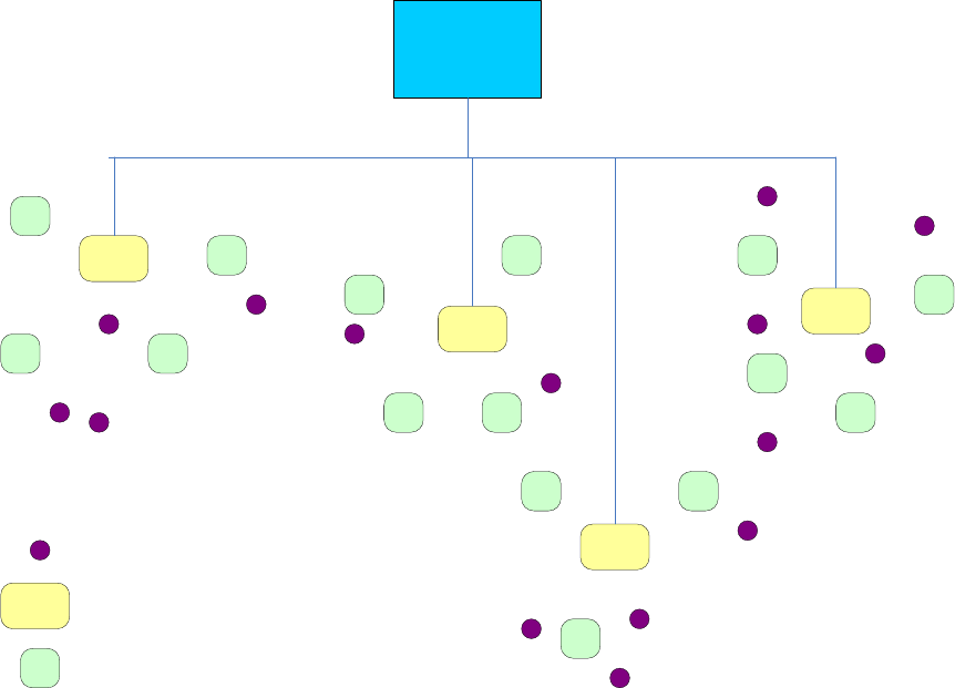
InTouch RFID Network high level architecture looks as follows:
Server
TAG
STAR
Spider
Figure 1: InTouch Network Architecture
STAR Installation and Operation
Installation
Stars should be installed as high as possible. It is preferred to attach them to the ceiling
upside down such that the antennas point downward. The antennas should be positioned
at 90 degrees to each other and perpendicular to each other. Stars can be fed through one
of two methods:
1. Power Over Ethernet (POE) or
2. External 3.3 volts power supply.
The STAR must be connected to the LOCAL AREA Network (LAN) which must be
connected to InTouch Server.
Operation
The STAR communicates with all InTouch Components and is responsible to
communicate information it receives to and from InTouch server. InTouch network can
support up to 128 STARs
Maintenance
STAR malfunction is immediately sensed by the InTouch Server. The Network needs to
be tested for before it is determined that the SART fails. In case, a STAR malfunctions it
should be replaced with one in inventory.
FCC NOTICE:
This equipment has been tested and found to comply with the limits for a Class B digital
device, pursuant to Part 15 of the FCC Rules. These limits are designed to provide
reasonable protection against harmful interference in a residential installation. This
equipment generates, uses and can radiate radio frequency energy and, if not installed and
used in accordance with the instructions, may cause harmful interference to radio
communications. If this equipment does cause harmful interference to radio or television
reception, which can be determined by turning the equipment off and on, the user is
encouraged to try to correct the interference by one or more of the following measures:
• Reorient or relocate the receiving antenna.
• Increase the separation between the equipment and the receiver.
• Consult the dealer or an experienced radio/TV technician for help.
• The carrier frequency is 904MHz – 926MHz.
• The RF output power (or field strength and measurement distance) is less than one
milliwatt.
TAG Operation
Installation
In order to initiate a TAG the user must install a battery in the TAG. The preferred
battery is CR 2335 that is enclosed in the TAG package. Other alternatives are CR2330
and CR2032. Both of the alternate batteries need a plastic shim that is included in the
package. There is no on/off button on the TAG and it will start operation as soon as the
battery is inserted. Also enclose in a pack of 10 TAGs a special tool to open and close the
battery door.
Operation
There are five buttons on the TAG: The three buttons on top are used to signal the server
a push button. The meaning of each button is programmable by the user on the PC level.
There are two buttons on the bottom. One is a theft detection button. When the TAG is
affixed to an asset the button is pressed in. If would be thief tries to remove the TAG
from the asset the button is released and a message is sent immediately to the server. The
second button is a reset button that allows a restart of the TAG in case, the TAG stops
operation due to shock or a voltage spike.
Maintenance
The batteries last about four years. The replacement process follows the same instructions
to install batteries.
FCC NOTICE:
This equipment has been tested and found to comply with the limits for a Class B digital
device, pursuant to Part 15 of the FCC Rules. These limits are designed to provide
reasonable protection against harmful interference in a residential installation. This
equipment generates, uses and can radiate radio frequency energy and, if not installed and
used in accordance with the instructions, may cause harmful interference to radio
communications. If this equipment does cause harmful interference to radio or television
reception, which can be determined by turning the equipment off and on, the user is
encouraged to try to correct the interference by one or more of the following measures:
• Reorient or relocate the receiving antenna.
• Increase the separation between the equipment and the receiver.
• Consult the dealer or an experienced radio/TV technician for help.
• The carrier frequency is 904MHz – 926MHz.
• The RF output power (or field strength and measurement distance) is less than one
milliwatt.
Spider Installation and Operation
Installation
Spiders, like STARs should be installed as high as possible. It is preferred to attach them
to the ceiling upside down such that the antennas point downward. The antennas should
be positioned at 90 degrees to each other and perpendicular to each other. Spiders are
battery operated by 6 D-Cell batteries
The Spiders communicate with the STARs wirelessly, so no wiring is needed. Once the
batteries are inserted, the on/off button should be moved to the on position. No more
operations are needed to set the Spiders.
Operation
The Spider communicates with other InTouch Components wirelessly. It also provides
maintenance information to the server, such as low battery indicator and the “health” of
its RF receiver signals from the STAR.
Maintenance
Once the low battery indicator sends the server the indication of low battery the batteries
will have about 1-2 month operational time. The batteries should be replaced as soon as
possible after such messages are generated.
Spiders should also be maintained if the communication with them stops or of poor
quality. This information is reported by the server.
FCC NOTICE:
This equipment has been tested and found to comply with the limits for a Class B digital
device, pursuant to Part 15 of the FCC Rules. These limits are designed to provide
reasonable protection against harmful interference in a residential installation. This
equipment generates, uses and can radiate radio frequency energy and, if not installed and
used in accordance with the instructions, may cause harmful interference to radio
communications. If this equipment does cause harmful interference to radio or television
reception, which can be determined by turning the equipment off and on, the user is
encouraged to try to correct the interference by one or more of the following measures:
• Reorient or relocate the receiving antenna.
• Increase the separation between the equipment and the receiver.
• Consult the dealer or an experienced radio/TV technician for help.
• The carrier frequency is 904MHz – 926MHz.
• The RF output power (or field strength and measurement distance) is less than one
milliwatt.
Warning:
Changes or modifications not expressly approved by the manufacturer could void
the user’s authority to operate the equipment.