Centrak IT104 Clear Router IT-104 User Manual Installation

Centrak, Inc. Clear Router IT-104 Installation

Contents

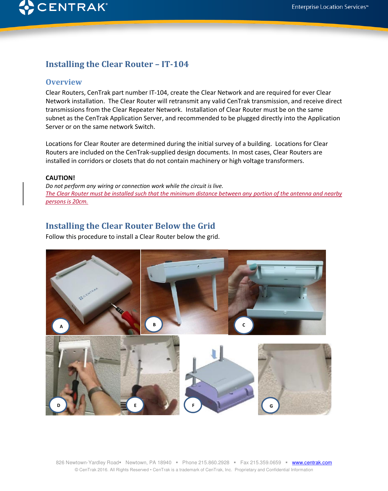
Installation User Manual

  826 Newtown-Yardley Road   Newtown, PA 18940      Phone 215.860.2928      Fax 215.359.0659      www.centrak.com © CenTrak 2016. All Rights Reserved • CenTrak is a trademark of CenTrak, Inc.  Proprietary and Confidential Information   Installing the Clear Router – IT-104 Overview Clear Routers, CenTrak part number IT-104, create the Clear Network and are required for ever Clear Network installation.  The Clear Router will retransmit any valid CenTrak transmission, and receive direct transmissions from the Clear Repeater Network.  Installation of Clear Router must be on the same subnet as the CenTrak Application Server, and recommended to be plugged directly into the Application Server or on the same network Switch.    Locations for Clear Router are determined during the initial survey of a building.  Locations for Clear Routers are included on the CenTrak-supplied design documents. In most cases, Clear Routers are installed in corridors or closets that do not contain machinery or high voltage transformers.  CAUTION! Do not perform any wiring or connection work while the circuit is live. The Clear Router must be installed such that the minimum distance between any portion of the antenna and nearby persons is 20cm.  Installing the Clear Router Below the Grid Follow this procedure to install a Clear Router below the grid.      ABCDEFG
  826 Newtown-Yardley Road   Newtown, PA 18940      Phone 215.860.2928      Fax 215.359.0659      www.centrak.com © CenTrak 2016. All Rights Reserved • CenTrak is a trademark of CenTrak, Inc.  Proprietary and Confidential Information  1. Attach a Star Ceiling mounting attachment to the drop-ceiling track at the designated location. For information on how to attach a Star Ceiling mounting attachment, see Installing the Star Ceiling Attachment. 2. Connect the Clear Router to the included Ethernet Cable and Transformer power supply. Do not plug in the transformer to a power source, or the Ethernet to a PoE source until the final step.  3. Remove the cover of the Clear Router. 4. Remove the cover of the Clear Router by following Steps A through C. 5. Life the Clear Router up to the Star Ceiling Attachment and align the slots, as seen in D and E. 6. Place the cover on the Clear Router as seen in figure F, and reinstall the Screw.  7. Unfold the antennas on the Clear Router to a 90° angle, as shown in Figure G. 8. Power the Clear Router.   Installing the Star Ceiling Attachment Follow this procedure to install the Star Ceiling Attachment on the drop-ceiling grid. CenTrak supplies four different Star Ceiling Attachments. Use the following table to select the appropriate Star Ceiling Attachment. The Star Ceiling Attachments are listed in order of grid width. Part Number Ceiling Grid Width Panel Type ITA-633 5/16 Inch Recessed ITA-361 9/16 Inch Recessed ITA-353 15/16 Inch Flush ITA-362 15/16 Inch Recessed  1. Separate the two parts of the Star Ceiling Attachment. 2. Lift up the ceiling panel and insert one half of the plastic Star Ceiling Attachment on the ceiling track. 3. Lift up the ceiling panel on the other side of the Grid and insert the other half of the Plastic Star Ceiling Attachment on the ceiling track. 4. Snap the two halves on the plastic Star Ceiling Attachment together.  This requires lifting the ceiling panels up slightly to slide the halves of the Star Ceiling Attachment into place.

Navigation menu