Central Hydraulics 2 Ton Foldable Shop Crane 35915 Users Manual Jack
2015-02-05
: Central-Hydraulics Central-Hydraulics-2-Ton-Foldable-Shop-Crane-35915-Users-Manual-530050 central-hydraulics-2-ton-foldable-shop-crane-35915-users-manual-530050 central-hydraulics pdf
Open the PDF directly: View PDF ![]() .
.
Page Count: 11
2 TON FOLDABLE SHOP CRANE
ASSEMBLY & OPERATING INSTRUCTIONS
Copyright © 1997 by Harbor Freight Tools®. All rights reserved. No portion of
this manual or any artwork contained herein may be reproduced in any shape or
form without the express written consent of Harbor Freight Tools.
For technical questions and replacement parts, please call 1-800-444-3353.
R
Model Model
Model Model
Model 35915
®
3491 Mission Oaks Blvd. / Camarillo, CA 93011
Visit our Web site at http//www.harborfreight.com
TO PREVENT SERIOUS INJURY,
READ AND UNDERSTAND ALL WARNINGS
AND INSTRUCTIONS BEFORE USE.

SKU 35915 For technical questions, please call 1-800-444-3353. Page 2
You will need this manual for the safety
instructions, assembly and operating instructions
and parts list. Put it in a safe, dry place for future
reference. Keep your invoice with this manual. Write
the invoice number on the inside of the front cover.
SAFETY WARNINGS & CAUTIONS
1. KEEP WORK AREA CLEAN. Cluttered areas invite injuries.
2. KEEP CHILDREN AWAY. All children should be kept away from the work area. Don’t
let them handle the tool.
3. DO NOT ASSEMBLE OR OPERATE THE CRANE IF UNDER THE INFLUENCE OF
ALCOHOL OR DRUGS. Read warning labels on prescriptions to determine if your
judgment or reflexes are impaired while taking drugs. If there is any doubt, do not
attempt to assemble or operate.
4. AVOID MOVING PARTS DURING OPERATION. Keep fingers and hands away from all
moving parts.
5. USE EYE PROTECTION. Wear ANSI approved impact safety goggles. Goggles are
available from Harbor Freight Tools.
6. DRESS SAFELY: Protective, gloves and nonskid footwear or safety shoes are
recommended when working with and operating the Crane. Don’t wear loose clothing or
jewelry. They can get caught in moving parts. Also, wear a protective hair covering to
prevent long hair from getting caught in the Crane.
7. DON’T OVERREACH. Keep proper footing and balance at all times.
8. STAY ALERT. Watch what you are doing. Use common sense. Do not operate any
tool when you are tired.
9. 2 TON LIMIT. Do not operate the hydraulic jack beyond rated capacity.
10. REPLACEMENT PARTS AND ACCESSORIES. When servicing, use only identical
replacement parts. Only use accessories intended for use with this Shop Crane.
Approved accessories are available from Harbor Freight Tools.
11. STORE IDLE EQUIPMENT. When not in use, Shop Crane should be stored in “closed”
position and in a dry location to reduce rust. For safety, store the Shop Crane in a
locked cabinet, out of reach of children.
SAVE THIS MANUAL
READ ALL INSTRUCTIONS
BEFORE ASSEMBLING OR
OPERATING THE SHOP CRANE.
SKU 35915 For technical questions, please call 1-800-444-3353. Page 3
UNPACKING
When unpacking the Shop Crane, check to make sure the following parts are included. If any
parts are missing or broken, please call Harbor Freight Tools at the number on the cover of this
manual.
Box A Box B
Item Description Qty Item Description Qty
1 BASE ASSEMBLY 1 7 SUPPORTS 2
2 JACK 1 8 POST 1
3 HANDLE 1 9 BOOM 1
4 JACK HANDLE 1 10 BOOM EXTENSION 1
6 LEGS 2 11 - 29 ASSEMBLY HARDWARE Lot
REV 05/99; 03/04; 10/04
ASSEMBLY
For safety and ease of assembly, use two people to assemble the Shop Crane.
WARNING!
To ensure safe operation, it is ESSENTIAL that the correct bolts are
used during assembly. If an improper bolt is used, this unit could fail,
potentially causing SERIOUS PERSONAL INJURY or DEATH.
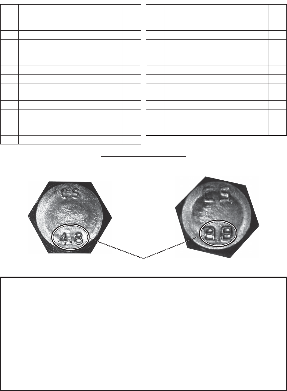
Carefully compare the bolts to the
Bolt Grade Identification
illustrations and
the measurements shown in the parts list on page 9, and the hardware diagrams
on the page 10 to make sure that the correct bolts are used in the correct place.
If any doubts arise regarding proper assembly, contact Harbor Freight Tools at
the number at the bottom of this page BEFORE use.
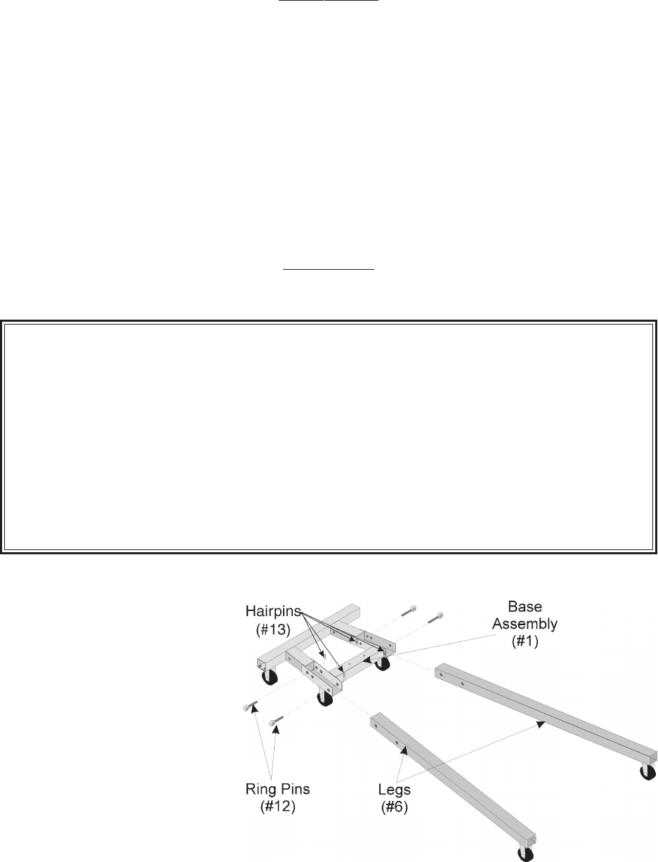
Step 1: Using four RING PINS (12), assemble the LEGS (6) to the BASE ASSEMBLY (1) - see
Figure 1.
Note: To insert the front RING
PINS, lift up on the front
of the BASE ASSEMBLY
until the holes line up.
After all four RING PINS
are inserted, insert one
HAIRPIN (13) though the
small hole at the end of
each of the RING PINS
until it snaps into place.
Make sure that all RING
PINS are secure before
proceeding.
Figure 1 — Assembling Legs
SKU 35915 For technical questions, please call 1-800-444-3353. Page 4
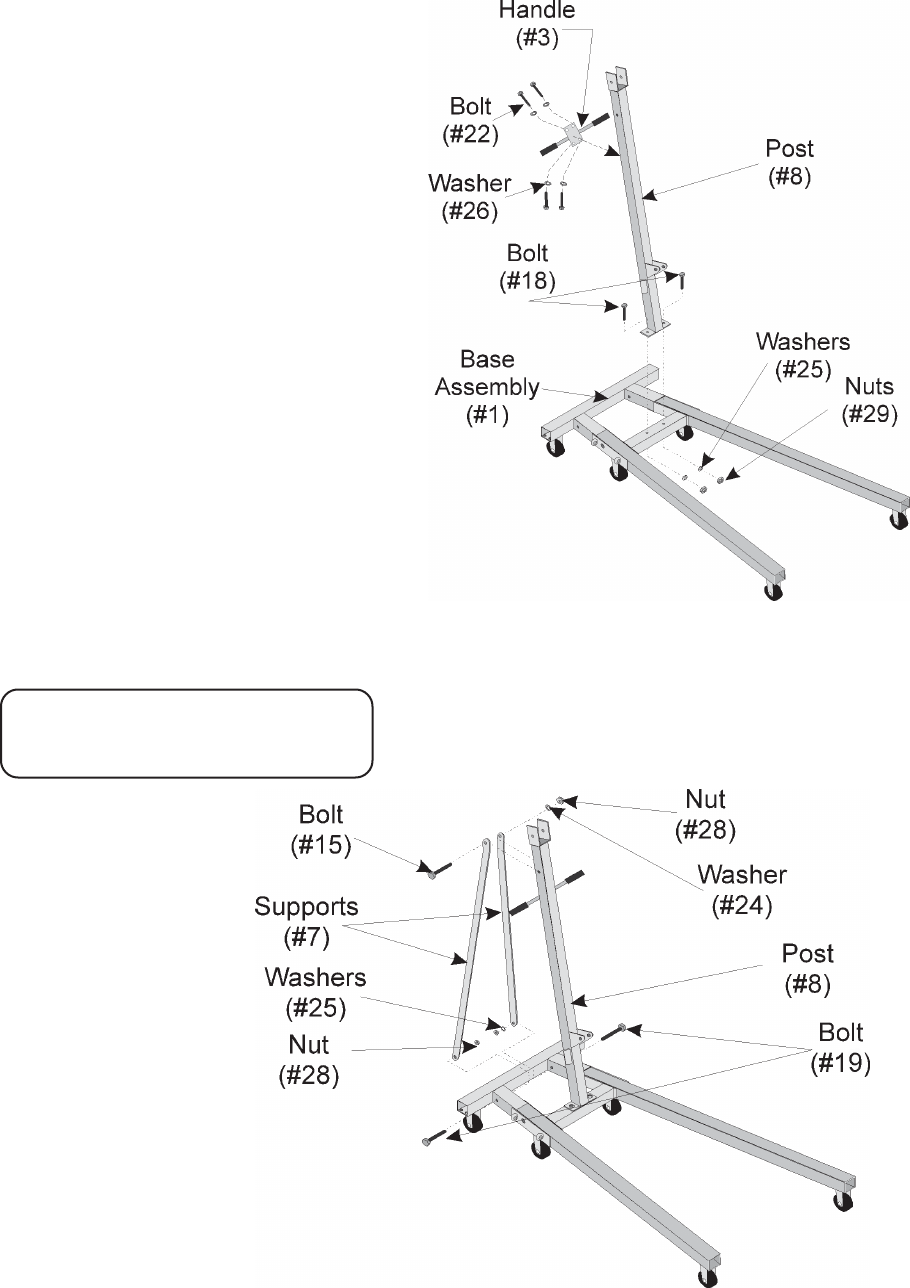
Step 2: Using four BOLTS (22) and
four WASHERS (26) assemble
the HANDLE (3) to the POST
(8). (See Figure 2).
Step 3: Using the BOLTS (19),
WASHERS (25), and NUTS
(29) secure the POST to the
BASE ASSEMBLY as shown in
Figure 2.
Step 4: Assemble the SUPPORTS
(7) to the BASE ASSEMBLY
using the two BOLTS (18),
WASHERS (25) and NUTS (29)
for the bottom of the
SUPPORTS and the BOLT (15),
WASHER (24), and NUT (28)
for the top as shown in Figure
3.
Figure 2 — Assembling the Post
onto the Base Assembly
NOTE:
The bends of the SUPPORTS face out
at the top and in at the bottom.
Figure 3 — Assembling the Supports
REV 10/04
SKU 35915 For technical questions, please call 1-800-444-3353. Page 5
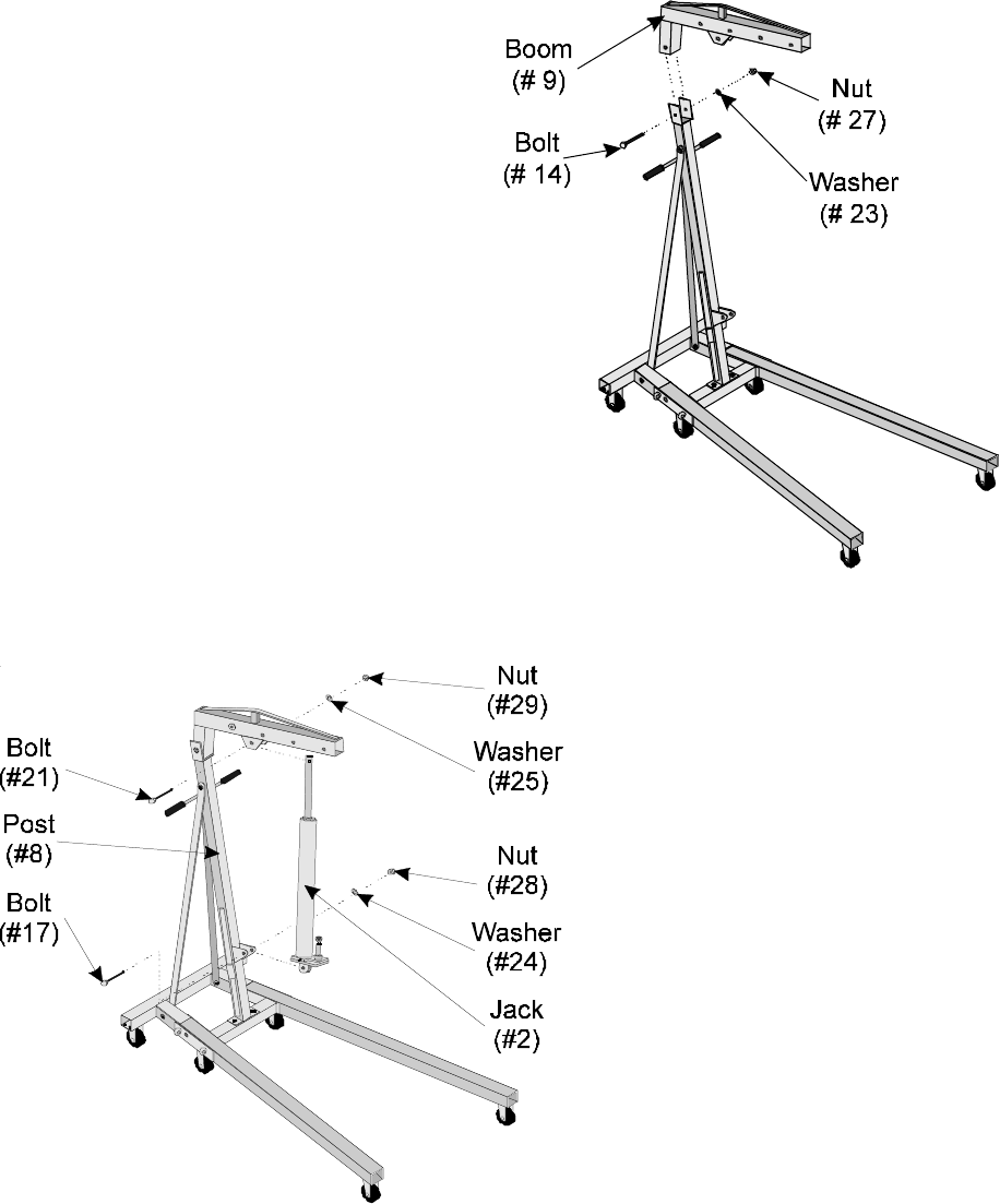
Step 5: Place the BOOM (9) onto the
POST (see Figure 4) and secure
with BOLT (14), WASHER (23) and
NUT (27).
Step 6: Assemble the lower end of the
JACK (2) to the POST using the
BOLT (17), WASHER (24) and NUT
(28) as shown in Figure 5.
Step 7: Secure the top of the JACK to
the BOOM using BOLT (21),
WASHER (25) and NUT (29). (See
Figure 5).
Figure 4 —
Placing the Boom onto Post
Figure 5 — Assembling the Jack to the Post and Boom
SKU 35915 For technical questions, please call 1-800-444-3353. Page 6
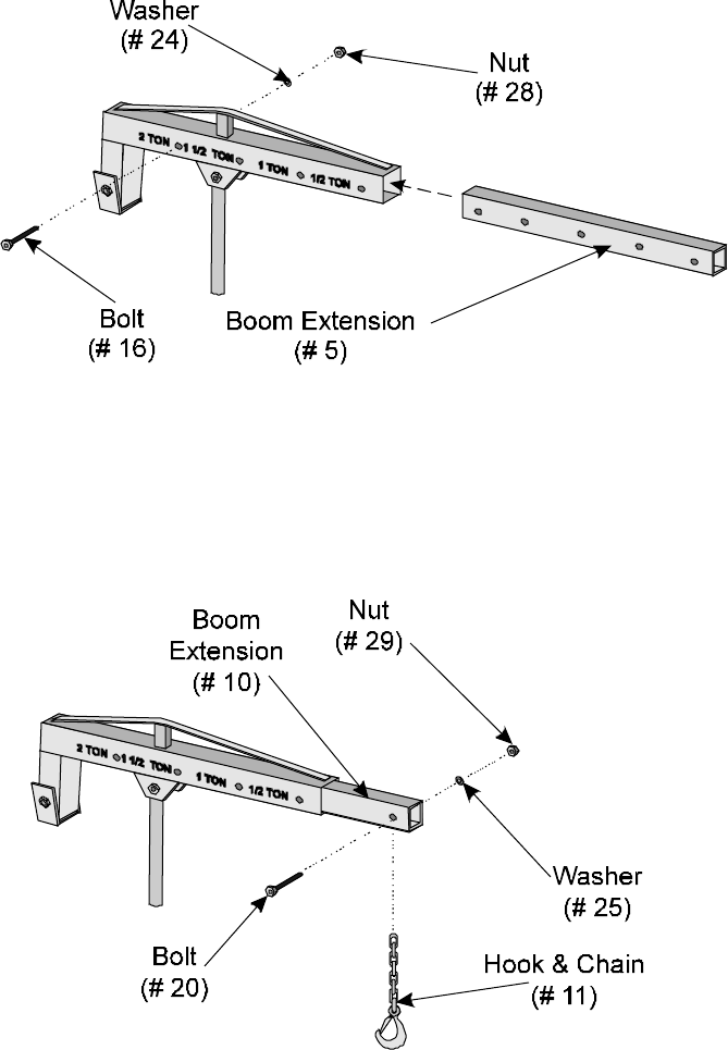
Step 8: Slide the BOOM EXTENSION (10) into the BOOM and secure, at the desired load
rating, using BOLT (16), WASHER (24) and NUT (28). (See Figure 6).
Figure 6 — Inserting the Boom Extension
Step 9: Attach the HOOK & CHAIN (11) to the end of the BOOM EXTENSION (See Figure 7)
using BOLT (20), WASHER (25) and NUT (29).
Figure 7 — Attaching the Hook & Chain
REV 05/99
SKU 35915 For technical questions, please call 1-800-444-3353. Page 7
OPERATION
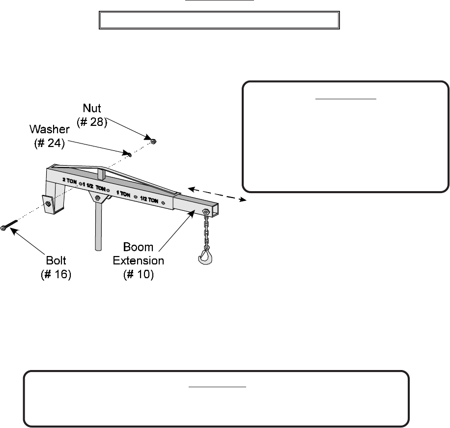
Step 1: Adjust the BOOM EXTENSION (10) to a weight limit position (See Figure 8) that
exceeds the weight you will be lifting. Securely tighten the BOLT (16), WASHER (24)
and NUT (28).
Figure 8 — Adjusting Boom Extension
Step 2: Move the Crane so that the HOOK & CHAIN (11) is directly above the item to be lifted.
Step 3: Securely attach the HOOK & CHAIN to the item.
Step 4: To raise the BOOM (9), turn the JACK’s (2) release valve fully clockwise (right). Insert
the HANDLE (3) into the JACK and pump (up and down) repeatedly until the item has
been lifted to the desired height.
Step 5: To lower the Crane, SLOWLY turn the JACK’s release valve counterclockwise (left).
WARNING:
Never stand under an object that is
being lifted by the Shop Crane. Be
aware of the possibility of a load
slipping off the HOOK & CHAIN (11).
An item that falls from the Crane can
cause serious injury.
CAUTION:
DO NOT MOVE THE CRANE WHEN UNDER LOAD. The Casters are
not designed to be rolled when the Crane is lifting heavy objects.
Note: Not to be used for aircraft purposes.
REV 10/04

SKU 35915 For technical questions, please call 1-800-444-3353. Page 8
Folding the Frame
Step 1: Lower Crane all the way.
Step 2: Remove HAIRPINS (13) from the front RING PINS (12). Remove the front RING PINS
(12). Leave rear RING PINS in.
Step 3: Raise LEG (6) until it rests against HANDLE (3).
Step 4: Insert a front RING PIN into the middle hole of the BASE ASSEMBLY (1).
Note: Be certain that, when unfolding, both RING PINS (12) and HAIRPINS (13) are placed
back in the proper places.
NOTE:
Do not fold crane while loaded.
REV 10/04
SKU 35915 For technical questions, please call 1-800-444-3353. Page 9
PARTS LIST
REV 05/99; 10/04
TRAPNOITPIRCSEDYT'QTRAPNOITPIRCSEDYT'Q
1YLBMESSAESAB171-3X61M(TLOB 9/61 8.8.RG)"1
2KCAJ181-4X41M(TLOB 5/61 8.4.RG)"2
3ELDNAH191-3X41M(TLOB 51 /61 8.4.RG)"2
4ELDNAHKCAJ102-3X41M(TLOB 1/88.8.RG)"1
6GEL212-3X61M(TLOB 3/48.8.RG)"1
7TROPPUS222X8M(TLOB 1/2)"4
8TSOP132)81M(REHSAW1
9MOOB142)61M(REHSAW4
01NOISNETXEMOOB152)41M(REHSAW5
11NIAHC&KOOH162)8M(REHSAW4
21NIPGNIR472)81M(TUN1
31NIPRIA
H482)61M(TUN4
41-4X81M(TLOB 5/61 8.8.RG)"192)41M(TUN5
51-4X61M(TLOB 5/61 8.4.RG)"103LAUNAM1
61-3X61M(TLOB.JDAMOOB 9/61 8.4.RG)"1
PLEASE READ THE FOLLOWING CAREFULLY
THE MANUFACTURER AND/OR DISTRIBUTOR HAS PROVIDED THE PARTS DIAGRAM
IN THIS MANUAL AS A REFERENCE TOOL ONLY. NEITHER THE MANUFACTURER NOR
DISTRIBUTOR MAKES ANY REPRESENTATION OR WARRANTY OF ANY KIND TO THE
BUYER THAT HE OR SHE IS QUALIFIED TO MAKE ANY REPAIRS TO THE PRODUCT OR
THAT HE OR SHE IS QUALIFIED TO REPLACE ANY PARTS OF THE PRODUCT. IN FACT,
THE MANUFACTURER AND/OR DISTRIBUTOR EXPRESSLY STATES THAT ALL REPAIRS
AND PARTS REPLACEMENTS SHOULD BE UNDERTAKEN BY CERTIFIED AND LICENSED
TECHNICIANS AND NOT BY THE BUYER. THE BUYER ASSUMES ALL RISK AND
LIABILITY ARISING OUT OF HIS OR HER REPAIRS TO THE ORIGINAL PRODUCT OR
REPLACEMENT PARTS THERETO, OR ARISING OUT OF HIS OR HER INSTALLATION OF
REPLACEMENT PARTS THERETO.
Grade Marking
Grade 4.8 Grade 8.8
Bolt Grade Identification
SKU 35915 For technical questions, please call 1-800-444-3353. Page 10
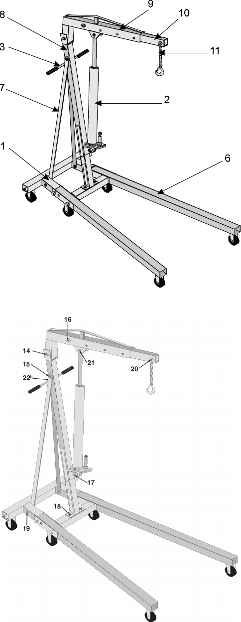
Figure 9a — Hardware Assembly Diagram
h = Hidden from view.
NOTE: Only the bolts are indicated on
this diagram. The Washers and
Nuts (parts 23-29) simply go
with the same size bolt.
Figure 9 — Parts Assembly Diagram
REV 10/04
NOTE: Some parts are listed and
shown for illustration purposes only
and are not available individually as
replacement parts.
SKU 35915 For technical questions, please call 1-800-444-3353. Page 11
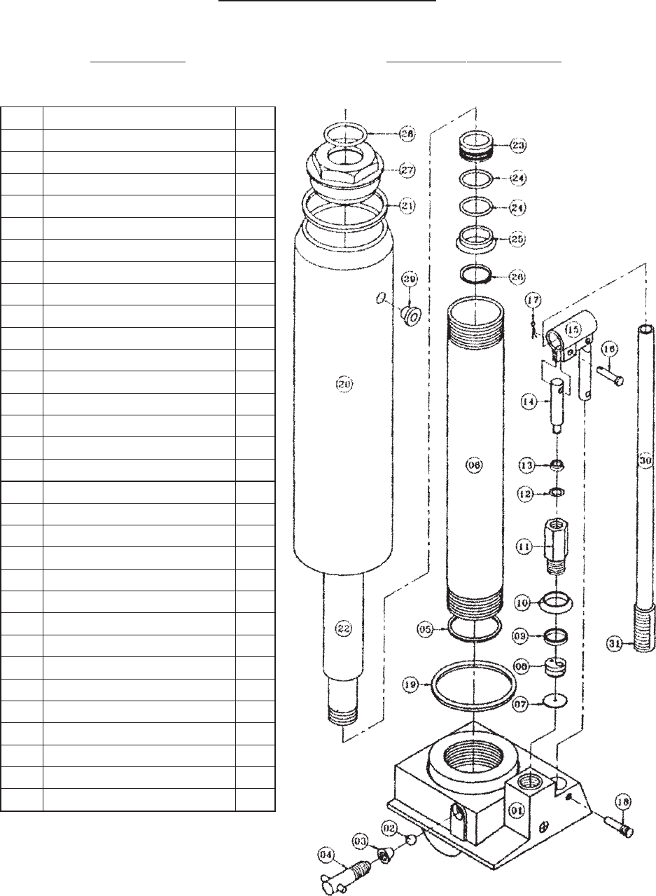
PARTS LIST
TRAPNOITPIRCSEDYT'Q
1TESESAB1
2LLABLEETS1
3LAES1
4WERCSESAELEREVLAV1
5REHSAW1
6REDNILYC1
7REHSAWREPPOC1
8EVLAV1
9LAES1
01REVOC1
11REDNI
LYCPMUP1
21GNIR-O1
31LAES1
41NOTSIP1
51YSSAMURCLUF®NULP1
61NIP1
71EPYTR-NIPRETTOC1
81TLOBKNIL1
91REHSAW1
02KNATLIO1
12REHSAW1
22MAR1
32RALLOC1
42GNIR-O2
52LAESPUC1
62GNIR-C1
72PACDNE1
82GNIR-O1
92REGNULP1
03ELDNAH1
13PIRG1
HYDRAULIC JACK
ASSEMBLY DIAGRAM
REV 10/04
