Central Pneumatic Air Compressor 94734 Users Manual
94734 94734
2015-02-03
: Central-Pneumatic Central-Pneumatic-Air-Compressor-94734-Users-Manual-467680 central-pneumatic-air-compressor-94734-users-manual-467680 central-pneumatic pdf
Open the PDF directly: View PDF ![]() .
.
Page Count: 14
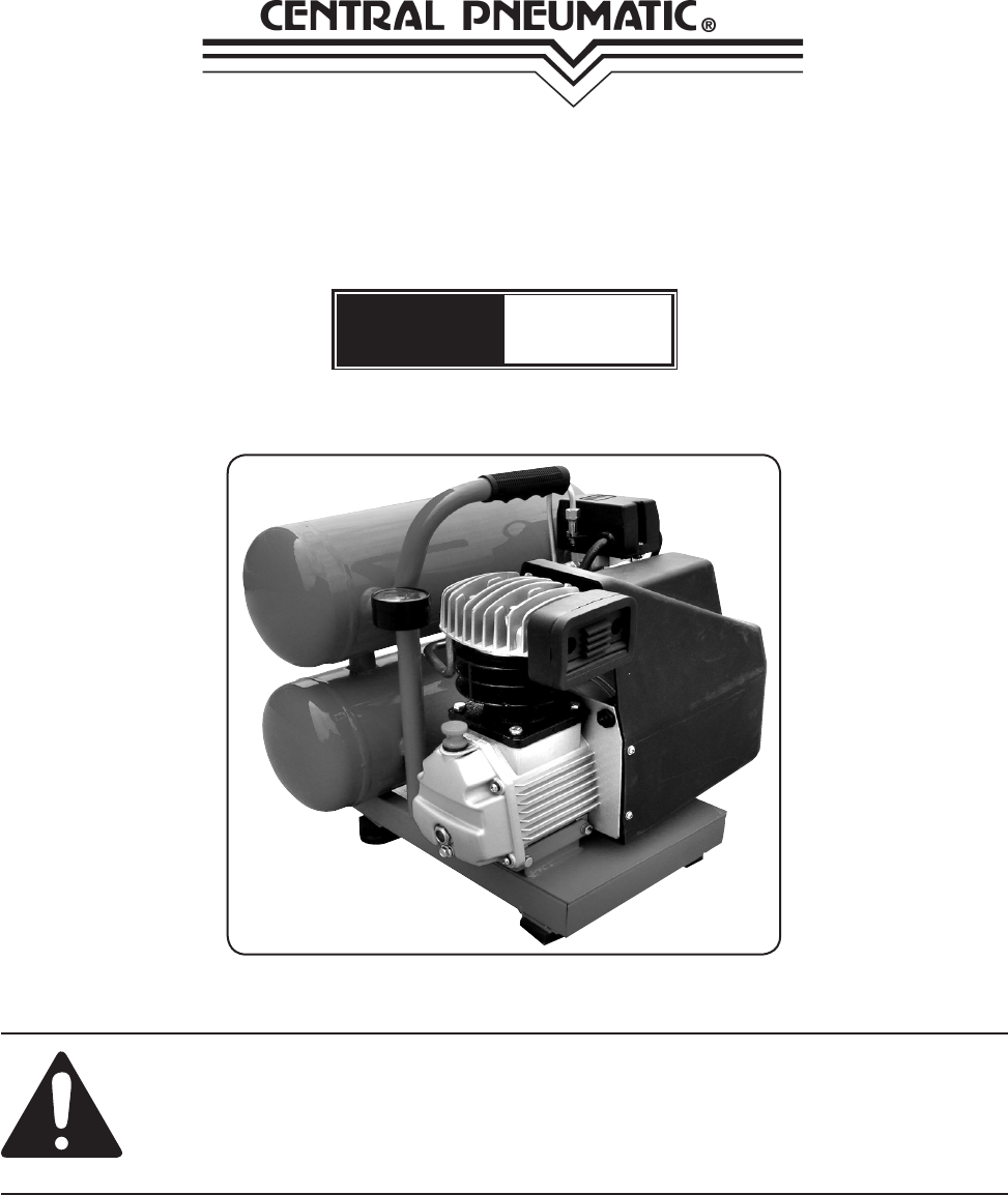
3 HP TWIN TANK AIR
COMPRESSOR
Model
94734
SET UP AND OPERATING INSTRUCTIONS
Visit our website at: http://www.harborfreight.com
Read this material before using this product.
Failure to do so can result in serious injury.
SAVE THIS MANUAL.
Copyright© 2006 by Harbor Freight Tools®. All rights reserved. No portion of this manual or any artwork con-
tained herein may be reproduced in any shape or form without the express written consent of Harbor Freight
Tools. Diagrams within this manual may not be drawn proportionally. Due to continuing improvements, actual
product may differ slightly from the product described herein. Tools required for assembly and service may not
be included.
For technical questions or replacement parts, please call 1-800-444-3353.
Revised Manual 10d
SKU 94734 For technical questions, please call 1-800-444-3353. Page 2
SPECIFICATIONS
Motor Power 13/4 HP (working), 3 HP (Peak), 1720 RPM;
120 V~, 60 Hz, 1 Phase, 11 A
Air Tank Size 5 gallons
Pump Single stage
Air Outlet Fitting Size 1/4 inch NPT barbed
Air Delivery 3.8 CFM at 90 PSI; 4.5 CFM at 70 PSI; and
5 CFM at 40 PSI
Pressure Switch On at 80 PSI; Off at 115 PSI
Safety Valve Releases pressure at 120 PSI
Features Pressure gauge, Overload reset button,
Auto shutoff
SAVE THIS MANUAL
You will need this manual for the safety warnings and precautions, assembly, oper-
ating, inspection, maintenance and cleaning procedures, parts list and assembly diagram.
Keep your invoice with this manual. Write the invoice number on the inside of the front
cover. Keep this manual and invoice in a safe and dry place for future reference.
GENERAL SAFETY RULES
WARNING!
READ AND UNDERSTAND ALL INSTRUCTIONS
Failure to follow all instructions listed below may
result in electric shock, re, and/or serious injury.
SAVE THESE INSTRUCTIONS
WORK AREA
Keep your work area clean and well lit.1. Cluttered benches and dark areas invite
accidents.
Do not operate compressors in explosive atmospheres, such as in the pres-2.
ence of ammable liquids, gases, or dust. Compressors create sparks which
may ignite the dust or fumes.
Keep bystanders, children, and visitors away while operating a compressor. 3.
Provide barriers or shields as needed.
#233060
REV 07b

SKU 94734 For technical questions, please call 1-800-444-3353. Page 3
ELECTRICAL SAFETY
Grounded compressors must be plugged into an outlet properly installed and 1.
grounded in accordance with all codes and ordinances. Never remove the
grounding prong or modify the plug in any way. Do not use any adapter plugs.
Check with a qualied electrician if you are in doubt as to whether the outlet
is properly grounded. If the compressors should electrically malfunction or break
down, grounding provides a low resistance path to carry electricity away from the
user.
Do not expose compressors to rain or wet conditions. 2. Water entering an elec-
tric motor will increase the risk of electric shock.
Do not abuse the Power Cord.3. Never use the Power Cord to pull the Plug from
an outlet. Keep the Power Cord away from heat, oil, sharp edges, or moving
parts. Replace damaged Power Cords immediately. Damaged Power Cords
increase the risk of electric shock.
AN EXTENSION CORD MUST 4. NEVER BE USED WITH THIS ITEM. Connecting
this item to an outlet through an extension cord MAY CAUSE ELECTRICAL
DAMAGE TO THE MOTOR and could present a FIRE HAZARD.
Always unplug the air compressor, and release the air pressure when not in use.5.
PERSONAL SAFETY
Stay alert. Watch what you are doing, and use common sense during use. Do 1.
not use while tired or under the inuence of drugs, alcohol, or medication. A
moment of inattention while operating may result in serious personal injury.
Dress properly. Do not wear loose clothing or jewelry. Contain long hair. 2.
Keep your hair, clothing, and gloves away from moving parts. Loose clothes,
jewelry, or long hair can be caught in moving parts.
Avoid accidental starting.3. Be sure the Power Switch is turned off before plug-
ging in. Plugging in compressors with the Power Switch on, invites accidents.
Remove adjusting keys or wrenches before turning the compressor on. 4. A
wrench or a key that is left attached to a rotating part of the compressor may result
in personal injury.
Do not overreach. Keep proper footing and balance at all times.5.
Use safety equipment. Always wear eye protection. 6. Make sure you are wearing
your protective clothing, safety glasses with side shields and dust mask or air respi-
rator, if appropriate.
TOOL USE AND CARE
Do not force the compressor. Use the correct compressor for your applica-1.
tion. The correct compressor will do the job better and safer at the rate for which it

SKU 94734 For technical questions, please call 1-800-444-3353. Page 4
is designed. Never attempt to force the compressor to provide more pressure than it
was designed for.
Do not use the compressor if the Power Switch does not turn it on or turn it 2.
off. Any compressor that cannot be controlled with the Power Switch is dangerous
and must be repaired or replaced.
Disconnect the Power Cord Plug from the power source before making any ad-3.
justments, changing accessories, or storing the compressor. Such preventive
safety measures reduce the risk of starting the compressor accidentally.
Keep idle compressors out of reach of children and other untrained persons. 4.
Compressors are dangerous in the hands of untrained users.
Maintain compressors with care. Keep all components of this product clean 5.
and dry. Do not use a damaged compressor. Tag damaged compressors “Do not
use” until repaired.
Check for misalignment or binding of moving parts, breakage of parts, and any 6.
other condition that may affect the compressor’s operation. If damaged, have
the compressor serviced before using. Many accidents are caused by poorly
maintained compressors.
Use only accessories that are recommended by the manufacturer for your 7.
model. Accessories that may be suitable for one compressor may become hazard-
ous when used on another compressor.
SERVICE
Compressor service must be performed only by qualied repair personnel. 1.
Service or maintenance performed by unqualied personnel could result in a risk of
injury.
When servicing a compressor, use only identical replacement parts. Follow 2.
instructions in the “Inspection, Maintenance, And Cleaning” section of this
manual. Use of unauthorized parts or failure to follow maintenance instructions may
create a risk of electric shock or injury.
SPECIFIC SAFETY RULES
CAUTION! Prior to its 1. rst use, and thereafter prior to each subsequent use,
make sure to ll the Air Compressor with a premium quality, 30 weight, non-
detergent compressor oil to the specied level. Running the Air Compressor
with no oil or with low oil will cause damage to the equipment and void its warranty.
Refer to the “Setup” instructions on page 7 for details on lling the Air Compressor
with oil.
When lling the Air Compressor with oil, make sure to 2. unscrew (do not pull)
the Oil Fill Cap to remove.
SKU 94734 For technical questions, please call 1-800-444-3353. Page 5
Use eye and ear protection. 3. Always wear ANSI-approved safety impact eye gog-
gles, and ear plugs when using the Air Compressor.
Make sure all tools and equipment used with the Air Compressor are rated to 4.
the appropriate air pressure capacity of the Air Compressor. Do not use any
tool or equipment that does not operate from 0-120 PSI. If necessary, check the
owner’s manual of the tool or equipment for its air pressure rating.
Always disconnect the Air Compressor from its electrical outlet, release any 5.
remaining air pressure from the unit, and disconnect all pneumatic tools and
equipment from the unit, before performing any services or maintenance, or
when not in use.
Avoid injury. Never direct the air jet at people or animals.6.
Inspect safety valve daily7. . If the safety valve is not working properly, tank pressure
can build up to dangerous levels. The tank could explode. For this reason, pull the
ring on the safety valve before each use and verify that it operates freely. Replace
safety valve if it does not operate freely.
Never remove or alter the factory sealed Safety Release Valve.
Do not attempt to readjust the automatic start and shutoff valves. 8. Any change
to the automatic ON/OFF pressure levels will cause additional stress on the motor,
which may result in shortened motor life.
Drain the Air Compressor’s air tank every day. 9. Do not allow moisture to build up
inside the Air Tank.
Do not unscrew the tank drain valve so that 10. more than four threads are show-
ing.
Avoid risk of tank explosion11. .
Avoid weakening of tank by draining condensation after each use.a.
Never modify tank by drilling holes, welding to it, or modifying it’s parts.b.
The tank is designed, and factory set, to operate within a specic pressure range. c.
For that reason, never make adjustments to, or substitute parts, to the compres-
sor.
Avoid bodily injury from moving parts12. . The compressor cycles on automatically,
without notice. For this reason, always keep hands and arms away from compressor
parts when the unit is connected to electrical power. Always have compressor safety
guards in place before turning compressor on.
Use approved air hose13. . Never use plastic or PVC pipe (unless specied for Air
Compressors) to carry air under pressure. Regardless of its pressure rating, it can
burst under pressure.
Never plug the power cord of this product into an electrical outlet while stand-14.
ing on a wet or damp surface.
REV 07b

SKU 94734 For technical questions, please call 1-800-444-3353. Page 6
THIS AIR COMPRESSOR MAY REQUIRE A DEDICATED ELECTRICAL CIRCUIT 15.
AS THE AMPERAGE DRAW UNDER FULL LOAD, COMBINED WITH USE OF
ANY OTHER ITEM, MAY OVERLOAD YOUR CIRCUIT.
Always turn off the Air Compressor in the event of a power failure.16.
Performance of this Air Compressor may vary depending on variations in local 17.
line voltage.
Maintain labels and nameplates on the Air Compressor.18. These carry important
information. If unreadable or missing, contact Harbor Freight Tools for a replace-
ment.
19. WARNING! People with pacemakers should consult their physician(s) before
using this product. Electromagnetic elds in close proximity to a heart pacemaker
could cause interference to or failure of the pacemaker.
20. WARNING! The brass components of this product contain lead, a chemical
known to the State of California to cause birth defects (or other reproductive harm).
(California Health & Safety code § 25249.5, et seq.)
21. WARNING! The warnings, precautions, and instructions discussed in this in-
struction manual cannot cover all possible conditions and situations that may occur.
It must be understood by the operator that common sense and caution are factors
which cannot be built into this product, but must be supplied by the operator.
SAVE THESE INSTRUCTIONS
UNPACKING
When unpacking, check to make sure all the parts shown on the Parts List at the
end of the manual are included. If any parts are missing or broken, please call Harbor
Freight Tools at the number shown on the cover of this manual as soon as possible.
IMPORTANT! This compressor is shipped with the oil ll plug removed and without oil.
The oil ll plug is attached to the power cord as a reminder to add oil to the crank-
case. Add oil to the proper level as explained on the next page and secure the oil ll
plug before use.
REV 07i
SKU 94734 For technical questions, please call 1-800-444-3353. Page 7
SETUP
Dipstick
Warning: Fill compressor with oil before using; running with NO OIL or with LOW
OIL will void the warranty. The optimal capacity of the oil reservoir is 7.8 ounces of
oil.
The Dipstick is used to determine if oil is needed. Never operate the compressor with-
out sufcient oil. Use a 30 weight, non-detergent compressor oil. To check the oil:
1. Unscrew the Dipstick.
2. Check the level of the oil. There are two lines on the bottom of the Dipstick. The oil
level should be somewhere between the two lines, as high as possible.
3. Add oil through the Dipstick’s hole as necessary, but do not overll. Always use a high
grade oil specially designed for air compressors. Never mix oils of different types.
Never use a low quality oil which may not afford adequate lubrication.
4. Replace the Dipstick.
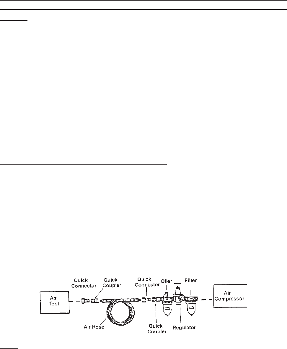
Install an Air Intake Filter and Hose (not included)
The lter and oiler (not supplied) are recommended but not mandatory for operation.
1. Remove and discard the plastic cap which covers the threaded hole at the top of the
Cylinder Case (B-6).
2. Screw the threaded part of the air lter assembly into the Cylinder Case until it is rmly
seated.
3. Connect the air tool, air hoses, lter, and oiler to the Compressor Air Output as
illustrated on the next page.
If the lter and oiler are not used, connect the air hose directly to the 1/4 inch NPT
barbed connector located at the Air Flow Valve (A-8). For easy connection or removal,
a quick coupler should be installed on the end of the air output.
Note: Use pipe thread seal tape on all threaded connections.

SKU 94734 For technical questions, please call 1-800-444-3353. Page 8
REV 07b
OPERATION
CAUTION! Prior to use, inspect the compressor for any damaged parts or unsafe con-
ditions. Make any necessary repairs before using again.
Turning Compressor On
1. Verify Tank Drain Valve (A-7) is closed.
2. Verify oil level is correct.
3. Verify that the Safety Valve (A-4) is operational.
4. Turn the Air Flow Valve (A-8) to the OFF position.
5. Plug the power cord into an electrical grounded 115 Volt AC electrical receptacle.
6. Rotate the Power Switch (A-5) to the Vertical position to turn the air compressor on.
Rotate that same switch to the horizontal position to turn it off. See page 10.
Note: Allow the pressure to build up to at least 80 PSI before using air.
Note: Motor will not start if tank pressure is already between 80-115 PSI. Pressure MUST
be below 80 PSI for motor to restart and build up pressure to the 115 PSI cut off
pressure.
7. Open the Air Flow Valve (A-8) and check for air leaks.
The operation of the compressor is automatic, as controlled by the internal pressure
switch. When the pressure drops below its operating range the compressor turns on.
When the pressure is above 115 PSI, the compressor shuts off.
Warning; The compressor will become very hot during operation. Do not touch the
cylinder area of the compressor, or allow ammable materials to come in contact with
the cylinder area.
Adjusting Pressure Gauge and Pressure Adjustment Screw
Caution: The Pressure Switch is adjustable but changes to the pressure levels are not
recommended; any change to the automatic ON/OFF pressure levels will cause addi-
tional stress on the motor which may shorten motor life.
Adjusting Air Output
1. When the Air Flow Valve (A-8) is to the right or left, the valve is closed. When it is in
the middle, it is open.
2. Turn the Air Flow Valve to the appropriate pressure.

SKU 94734 For technical questions, please call 1-800-444-3353. Page 9
MAINTENANCE
WARNING! Do not make any repairs, adjustments, or maintenance on the air compressor
unless it is disconnected from the electrical power and the tank pressure is released.
Maintenance should always be performed by a qualied technician.
1. Check the oil level before each use. If the oil is low, add some. If it is high, drain some
by removing the Drain Plug. Replace the oil once a year.
2. Check and clean the Air Filter (B-5) every 50 hours, or sooner if used in a dusty
environment.
3. Drain the air tanks after each use by opening the drain petcock or the Tank Drain
Valve (A-7). Leave open until the next use.
4. After the compressor has cooled down, clean it with a damp rag containing mild
detergent and water. Do not use ammable liquids or solvents.
PARTS LIST “A”
Item Description Qty
A-1 Compressor Assembly 1
A-2 Pressure Gauge 1
A-3 Rubber Grip 1
A-4 Safety Valve 1
A-5 ON/OFF Switch 1
A-6 Air Tank 2
A-7 Tank Drain Valve 1
A-8 Air Flow Valve 1
A-9 One Way Valve 1
A-10 Air Tube 1
A-11 Base 1
A-12 Rubber Foot 1
A-13 Bolt and Nut 1 ea.
A-14 Air Unloader Tube 1
Note: Some parts are listed and shown for illustration purposes only and are not available
individually as replacement parts.
PLEASE READ THE FOLLOWING CAREFULLY
THE MANUFACTURER AND/OR DISTRIBUTOR HAS PROVIDED THE PARTS DIAGRAM IN THIS MANUAL
AS A REFERENCE TOOL ONLY. NEITHER THE MANUFACTURER NOR DISTRIBUTOR MAKES ANY
REPRESENTATION OR WARRANTY OF ANY KIND TO THE BUYER THAT HE OR SHE IS QUALIFIED TO
MAKE ANY REPAIRS TO THE PRODUCT OR THAT HE OR SHE IS QUALIFIED TO REPLACE ANY PARTS
OF THE PRODUCT. IN FACT, THE MANUFACTURER AND/OR DISTRIBUTOR EXPRESSLY STATES THAT
ALL REPAIRS AND PARTS REPLACEMENTS SHOULD BE UNDERTAKEN BY CERTIFIED AND LICENSED
TECHNICIANS AND NOT BY THE BUYER. THE BUYER ASSUMES ALL RISK AND LIABILITY ARISING OUT OF
HIS OR HER REPAIRS TO THE ORIGINAL PRODUCT OR REPLACEMENT PARTS THERETO, OR ARISING
OUT OF HIS OR HER INSTALLATION OF REPLACEMENT PARTS THERETO.
REV 10d
SKU 94734 For technical questions, please call 1-800-444-3353. Page 10
Note: The Air Compressor is equipped with an external overload device. Should the Air
Compressor experience a short or excessive load, the overload device will trip and
the machine will automatically shut down. If this happens, turn Off the Power Switch
(A5), wait 10 minutes and check for any obvious problems. Reset the Overload
Protection Button (41) then, turn On the Power Switch to restart the Air Compressor.
See Drawing “A” below.
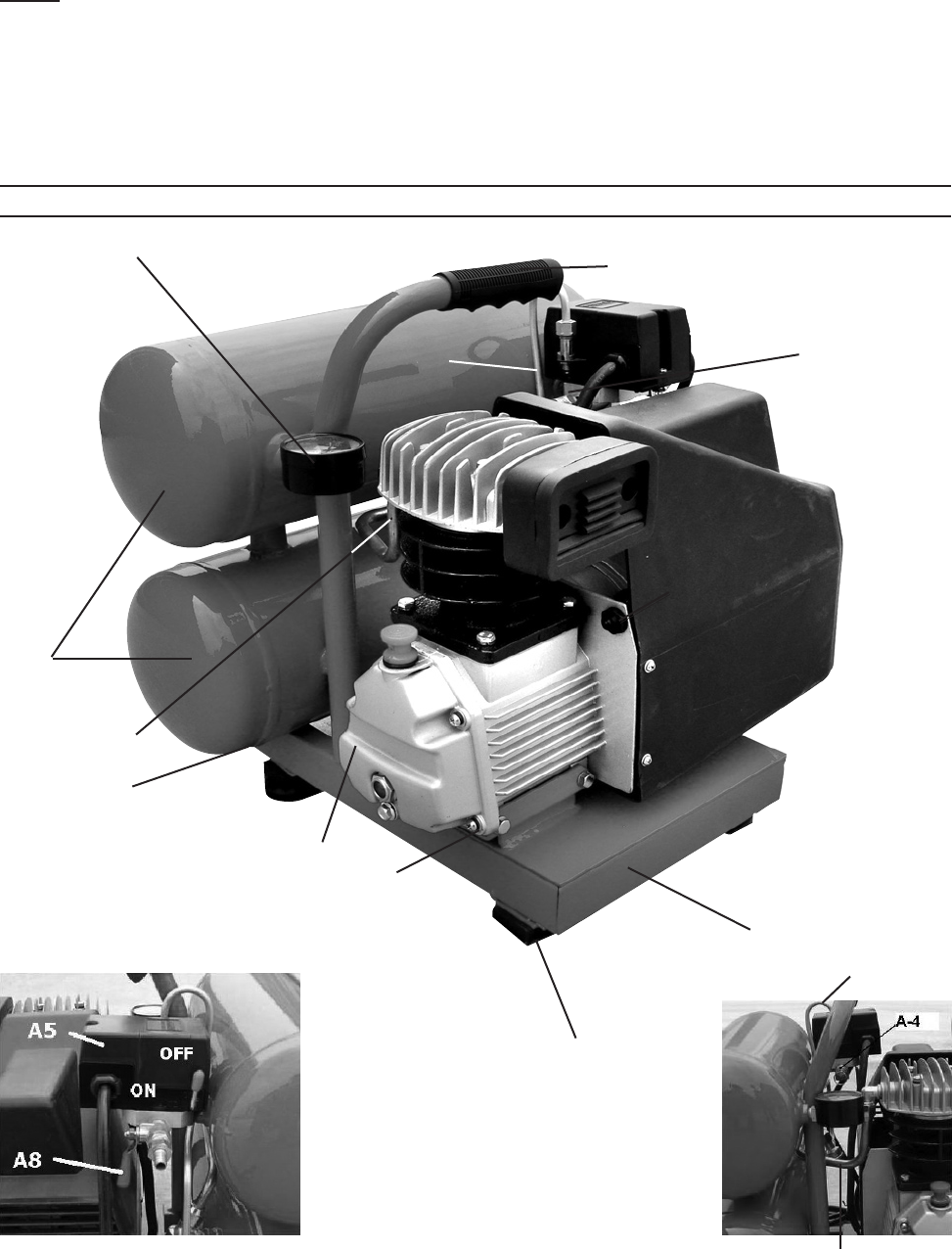
ASSEMBLY DRAWING “A”
A3
A5
A2
A11
A13
A1
A6
A14
A12
A9
A7 (under the tank)
on
(41) Overload
Protection
Button
REV 07b; 10d
A10
A14
A10

SKU 94734 For technical questions, please call 1-800-444-3353. Page 11
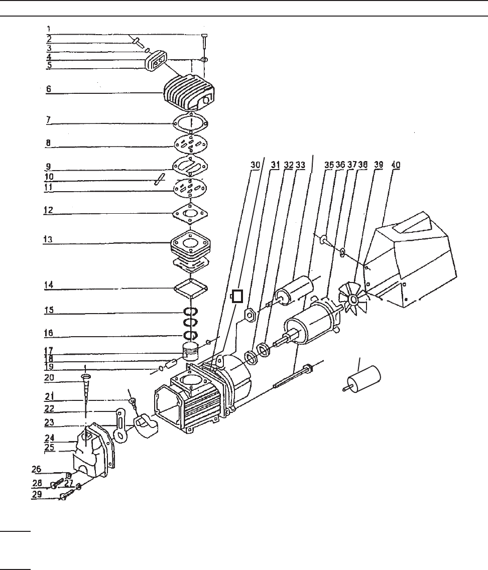
PARTS LIST “B”
Item Description Qty
B-1 Screw 1
B-2 Screw 1
B-3 Washer 1
B-4 Washer 1
B-5 Air Fliter 1
B-6 Cylinder Case 1
B-7 Gasket, Crankshaft Cover 1
B-8 Valve Seat 1
B-9 Gasket, Valve Seat 1
B-10 Valve Plate 1
B-11 Valve Seat 1
B-12 Gasket, Valve Seat 1
B-13 Cylinder 1
B-14 Cylinder Gasket 1
B-15 Compression Ring 1
B-16 Scraping Oil Ring 1
B-17 Piston 1
B-18 Piston Pin 1
B-19 Crankshaft Retainer 1
B-20 Dip Stick 1
B-21 Screw 1
Item Description Qty
B-22 Connecting Rod 1
B-23 Crankshaft 1
B-24 Gasket, Front Cover 1
B-25 Front Cover 1
B-26 Washer 1
B-27 Washer 1
B-28 Bolt - Oil Drain 1
B-29 Screw 1
B-30 Crankshaft Case 1
B-31 Nut 1
B-32 Seal Washer 1
B-33 Bearing 1
B-34A Stating Capacitor (80 µF) 1
B-34b Running Capacitor (70 µF) 1
B-35 Bolt 1
B-36 Screw 1
B-37 Motor 1
B-38 Washer 1
B-39 Radiating Fan Wheel 1
B-40 Radiating Cover 1
B-41 Thermal Switch 1
REV 07b
SKU 94734 For technical questions, please call 1-800-444-3353. Page 12
ASSEMBLY DRAWING “B”
41 34A
34B
Note: When ordering parts on this page, add the prex “B” to the part number (Example:
B-1 is a Screw)
Note: Some parts are listed and shown for illustration purposes only and are not available
individually as replacement parts
REV 07b
SKU 94734 For technical questions, please call 1-800-444-3353. Page 13
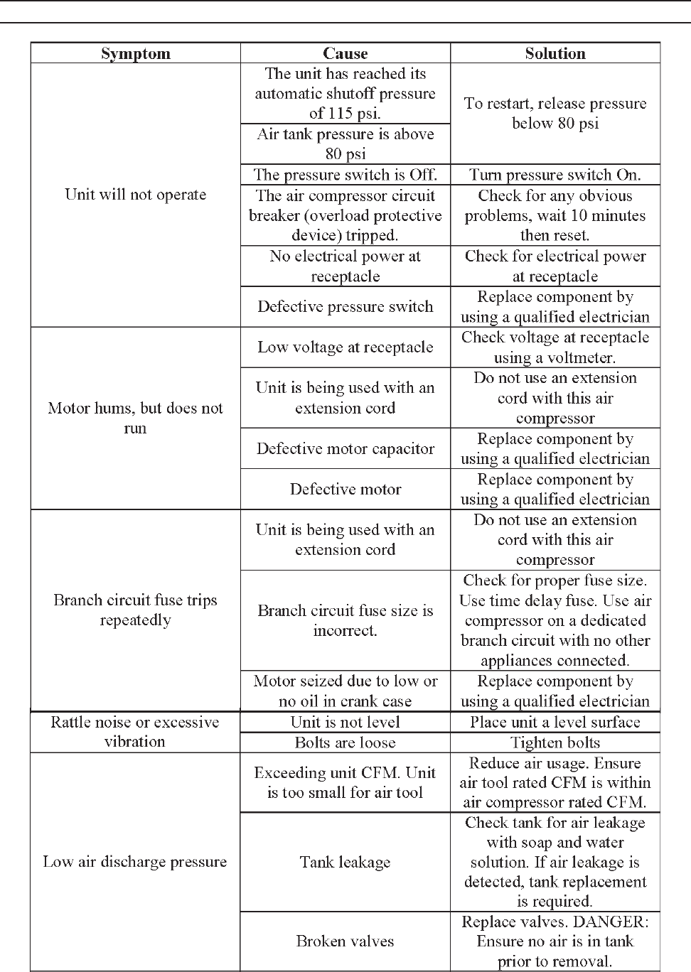
TROUBLESHOOTING GUIDE
REV 07b

SKU 94734 For technical questions, please call 1-800-444-3353. Page 14
TROUBLESHOOTING GUIDE (CONTINUED)
Symptom Cause Solution
Circuit breaker (overload
protection device) trips repeatedly
Unit is being used with an
extension cord
Do not use an extension cord with
this product.
Low voltage at receptacle. Check voltage at receptacle.
Excessive moisture at air outlet. Water in tank Drain water from tank
REV 07b
LIMITED 1 YEAR / 90 DAY WARRANTY
Harbor Freight Tools Co. makes every effort to assure that its products meet high
quality and durability standards, and warrants to the original purchaser that for a period of
one year from date of purchase that the tank is free of defects in materials and workman-
ship (90 days if used by a professional contractor or if used as rental equipment). Harbor
Freight Tools also warrants to the original purchaser, for a period of ninety days from date
of purchase, that all other parts and components of the product are free from defects in
materials and workmanship. This warranty does not apply to damage due directly or indi-
rectly to misuse, abuse, negligence or accidents, repairs or alterations outside our facilities,
normal wear and tear, or to lack of maintenance. We shall in no event be liable for death,
injuries to persons or property, or for incidental, contingent, special or consequential dam-
ages arising from the use of our product. Some states do not allow the exclusion or limita-
tion of incidental or consequential damages, so the above limitation of exclusion may not
apply to you. THIS WARRANTY IS EXPRESSLY IN LIEU OF ALL OTHER WARRANTIES,
EXPRESS OR IMPLIED, INCLUDING THE WARRANTIES OF MERCHANTABILITY AND
FITNESS.
To take advantage of this warranty, the product or part must be returned to us with
transportation charges prepaid. Proof of purchase date and an explanation of the complaint
must accompany the merchandise. If our inspection veries the defect, we will either repair
or replace the product at our election or we may elect to refund the purchase price if we
cannot readily and quickly provide you with a replacement. We will return repaired prod-
ucts at our expense, but if we determine there is no defect, or that the defect resulted from
causes not within the scope of our warranty, then you must bear the cost of returning the
product.
This warranty gives you specic legal rights and you may also have other rights
which vary from state to state.
3491 Mission Oaks Blvd. • PO Box 6009 • Camarillo, CA 93011 • (800) 444-3353
