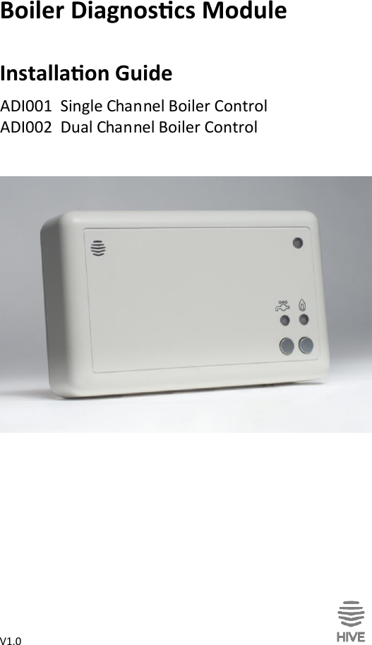
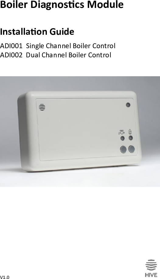
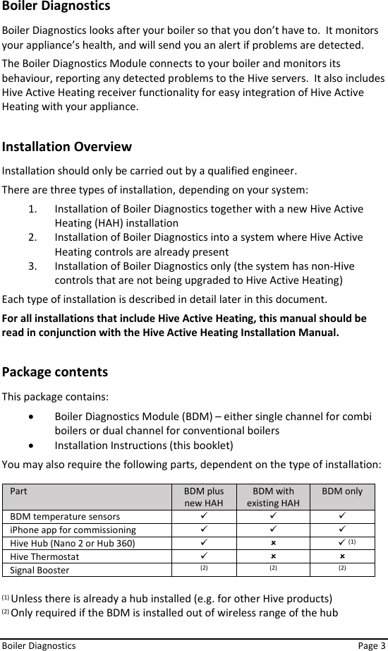
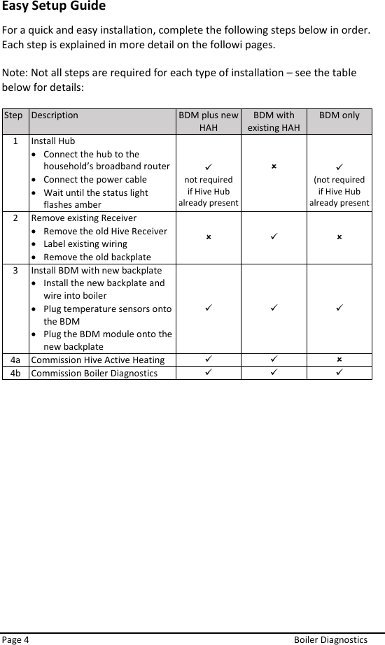
Centrica Hive ADI001 Heating Controls and monitoring device User Manual

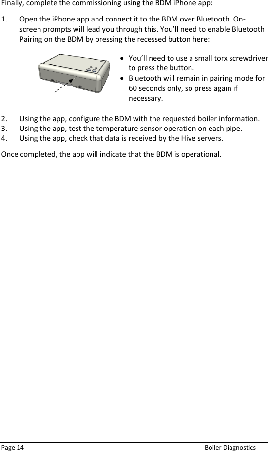
Centrica Connected home Limited Heating Controls and monitoring device

User Manual

V1.0     Boiler Diagnoscs Module  Installaon Guide                  ADI001  Single Channel Boiler Control  ADI002  Dual Channel Boiler Control
 Page 2  Boiler Diagnostics
 Boiler Diagnostics    Page 3 Boiler Diagnostics Boiler Diagnostics looks after your boiler so that you don’t have to.  It monitors your appliance’s health, and will send you an alert if problems are detected.  The Boiler Diagnostics Module connects to your boiler and monitors its behaviour, reporting any detected problems to the Hive servers.  It also includes Hive Active Heating receiver functionality for easy integration of Hive Active Heating with your appliance.  Installation Overview Installation should only be carried out by a qualified engineer. There are three types of installation, depending on your system: 1. Installation of Boiler Diagnostics together with a new Hive Active Heating (HAH) installation 2. Installation of Boiler Diagnostics into a system where Hive Active Heating controls are already present 3. Installation of Boiler Diagnostics only (the system has non-Hive controls that are not being upgraded to Hive Active Heating) Each type of installation is described in detail later in this document. For all installations that include Hive Active Heating, this manual should be read in conjunction with the Hive Active Heating Installation Manual.  Package contents This package contains: • Boiler Diagnostics Module (BDM) – either single channel for combi boilers or dual channel for conventional boilers • Installation Instructions (this booklet) You may also require the following parts, dependent on the type of installation:  Part BDM plus new HAH BDM with existing HAH BDM only BDM temperature sensors ✓ ✓ ✓ iPhone app for commissioning ✓ ✓ ✓ Hive Hub (Nano 2 or Hub 360) ✓      ✓ (1) Hive Thermostat ✓   Signal Booster (2) (2) (2)  (1) Unless there is already a hub installed (e.g. for other Hive products) (2) Only required if the BDM is installed out of wireless range of the hub
 Page 4  Boiler Diagnostics Easy Setup Guide For a quick and easy installation, complete the following steps below in order. Each step is explained in more detail on the followi pages.  Note: Not all steps are required for each type of installation – see the table below for details:  Step Description BDM plus new HAH BDM with existing HAH BDM only 1 Install Hub • Connect the hub to the household’s broadband router • Connect the power cable • Wait until the status light flashes amber   ✓ not required if Hive Hub already present     ✓ (not required if Hive Hub already present 2 Remove existing Receiver  • Remove the old Hive Receiver • Label existing wiring • Remove the old backplate  ✓  3 Install BDM with new backplate • Install the new backplate and wire into boiler • Plug temperature sensors onto the BDM • Plug the BDM module onto the new backplate ✓ ✓ ✓ 4a Commission Hive Active Heating ✓ ✓  4b Commission Boiler Diagnostics ✓ ✓ ✓
 Boiler Diagnostics    Page 5 STEP 1 - Install the hub  If a compatible Hive-branded hub is not already present in the home, one must be installed (if there is already a Hive Hub in the home, skip to page 7, ‘Compatible hub already present).  To install the hub, there must be a broadband connection with a spare network port.  There must also be a power socket nearby. Once these have been located, connect the hub as follows:                Fit the power cable into the hub and plug it into the power socket. Connect the hub to the household’s broadband router using the network cable provided.
 Page 6  Boiler Diagnostics  Once the amber light is flashing, the hub is set up and you can move on to the next installation step.  Hub Lights What does this mean Notes No lights No power to hub Check that all cables are connected and that the power socket works. Green flashing Installation and start up. The hub is attempting to connect to the servers and update itself. Do not disconnect the hub. If flashing continues after 15 minutes, use the Hive Engineer App or contact Technical Support to confirm it has connected Amber flashing Installation. The hub is trying to connect to a BDM module. Confirm that the BDM is correctly installed. The hub will search for devices for 2 hours at a time. It will then pause and show solid amber. Amber solid Installation. The hub has paused its search for a BDM module. To restart the search on a freshly installed hub, turn the hub off and on. Amber flashing light should then return. Green solid Normal operation. The hub is connected. BDM module is installed. Red Error. The hub has failed to connect to the Hive servers. Check the hub is plugged in and the broadband connection is working. Call Technical Support if problems persist.  Wait for an amber flashing light. During start up the green light will flash, followed by the amber light. This usually takes 5-10 minutes.
 Boiler Diagnostics    Page 7 Compatible hub already present  If a compatible Hive-branded hub (Nano 2 or later) is already installed in the home, then simply press and hold the button on the side of the hub until the middle status light starts to flash amber. Once the hub’s amber light is flashing, you can move onto the next installation step.
 Page 8  Boiler Diagnostics STEP 2 - Remove Existing Hive Receiver If there is an existing Hive Receiver installed on the system, this will need to be removed.  This step is not required if this is a new Hive Active Heating install or if this is a Boiler Diagnostics only install.  Important information: Before you get started   • Before fitting, isolate the mains electricity supply to the central heating system. Confirm it is isolated and secured in the off position for the duration of the installation. Remember to always follow appropriate safe electrical isolation procedures and test to confirm that the supply is isolated before touching any electrical connections.  • This product should only be installed by an electrically skilled person competent in the installation of electrical accessories. The wiring must comply to the current edition of BS7671 (The IET Wiring Regulations), and the appropriate Building Regulations or Standards in place.  • The BDM is double insulated so doesn’t need an earth connection. You’ll find a tether on the backplate to secure an earth wire if needed.  • This product is designed for fixed wiring installation only. It must be supplied via a switched fused spur with a minimum contact separation of 3mm (both live and neutral) and fitted with a 3A fuse.           Loosen the screws on the underside of the Receiver and, lifting from the bottom, remove the receiver from the backplate.   1 Remove the existing backplate, making a note of the locations of the wiring.   2
 Boiler Diagnostics    Page 9 STEP 3 - Install the BDM  Important information: Before you get started   • Before fitting, isolate the mains electricity supply to the central heating system. Confirm it is isolated and secured in the off position for the duration of the installation. Remember to always follow appropriate safe electrical isolation procedures and test to confirm that the supply is isolated before touching any electrical connections.  • This product should only be installed by an electrically skilled person competent in the installation of electrical accessories. The wiring must comply to the current edition of BS7671 (The IET Wiring Regulations), and the appropriate Building Regulations or Standards in place.  • The BDM is double insulated so doesn’t need an earth connection. You’ll find a tether on the backplate to secure an earth wire if needed.  • This product is designed for fixed wiring installation only. It must be supplied via a switched fused spur with a minimum contact separation of 3mm (both live and neutral) and fitted with a 3A fuse.   Installing the correct BDM There are two types of Boiler Diagnostics Module  • Single channel BDM - for combi boilers      • Dual channel BDM - for conventional boilers with hot water tanks
 Page 10  Boiler Diagnostics 3a – Installing the BDM You should fit the BDM in a convenient location close to the boiler or central heating system. Make sure it’s at least 30cm away from large metal objects, such as a boiler or hot water cylinder, to avoid interference with radio signals. Take care to avoid any cables and pipes that may be buried in the walls. Once you’ve found a suitable location, install the BDM as follows:                              Loosen the screws on the underside of the BDM and remove the backplate by pulling the bottom of it away from the front panel.   Fix the backplate to the wall with the terminals at the top.   Run suitable cables from the boiler or wiring centre (as required) and then continue on to the next section to wire up the backplate. 1 2 3
 Boiler Diagnoscs    Page 11 3b - Single channel BDM wiring  3c - Dual channel BDM wiring   3d – Aaching the temperature sensors Clip the sensors on to the boiler pipes as labelled – see instrucons provided with the sensors for details. Aach the sensor loom to the BDM as shown below:              BN: Neutral supply to boiler  BL: Live supply to boiler  N: Permanent neutral from spur L: Permanent live from spur 1: Common 2: Heang off (NC) 3: Heang on (NO) 4: Unused N: Spare permanent neutral L: Spare permanent live   BN: Neutral supply to boiler BL: Live supply to boiler N: Permanent neutral from spur L: Permanent live from spur 1: Hot water off (NC) 2: Heang off (NC) 3: Hot water on (NO) 4: Heang on (NO) N: Spare permanent neutral L: Spare permanent live   Temperature sensor  loom plugs in here
 Page 12  Boiler Diagnostics 3e – Attaching the BDM to the backplate Place the top edge of the BDM onto the top of the backplate, engaging the retaining hooks on the backplate. Push the BDM onto the backplate and then tighten the retaining screws.      3f - Additional Installation Information Replacing an existing thermostat  If you’re replacing an existing wired thermostat, you should ensure that the pre-existing wires and connections are made safe. This can be achieved by disconnecting or bridging out the wired thermostat in the wiring centre or boiler. Where cables are left at the wireless thermostat position, they should be housed and terminated within an enclosure to prevent access. If you’re replacing an existing wireless thermostat, decommission it by detaching it from the wall and removing its batteries.  Gravity-fed and part-pumped systems  Gravity-fed and part-pumped systems are wired differently to standard boilers. With these, the hot water relay switches on the boiler, whilst the heating relay opens a valve, operates a pump, or both, to divert hot water to the heating. If you are installing into a gravity-fed or part pumped system, complete the wiring and then switch the BDM to ‘gravity-fed’ mode as follows:   1. Switch off the power to the boiler and BDM  2. Wait at least 5 seconds, then switch the boiler and BDM back on  3. Press and hold the hot water button for at least 10 seconds   The BDM status light will flash BLUE for 3 seconds when entering ‘gravity-fed’ mode. Or GREEN for ‘fully pumped’ mode. Fully pumped mode is the default for new devices.
 Boiler Diagnostics    Page 13 STEP 4 - Commissioning Commissioning uses the BDM iPhone App to connect to the BDM over Bluetooth, leading you step-by-step through the required process. The process varies dependant on whether the system includes Hive Active Heating or not. Boiler Diagnostics Only install 1. Open the iPhone app and connect it to the BDM over Bluetooth. On-screen prompts will lead you through this. You’ll need to enable Bluetooth Pairing on the BDM by pressing the recessed button here:        2. Using the app, disable the Hive Receiver functionality within the BDM. 3. Using the app, configure the BDM with the requested boiler information. 4. Using the app, test the temperature sensor operation on each pipe. 5. Using the app, check that data is received by the Hive servers. Once completed, the app will indicate that the BDM is operational. Boiler Diagnostics and Hive Active Heating install First, the Hive Active Heating functionality must be tested.  To test the BDM to boiler connection follow these steps:  1. Visually check the wiring to confirm that the connections have been carried out correctly, referring to the labels on the wires and any photographs taken before replacement began. 2. Confirm that the BDM’s front panel is in place and that it is safe to commission the boiler. 3. Check the middle light on the Hub is flashing Amber – if it isn’t, go back to step 1 above to check the wiring.  4. Restore power to the heating system – the BDM’s status light should flash AMBER. This means it’s ready to connect to the hub and thermostat. 5. Test the BDM’s wiring to the heating system by pressing the Central heating button. The GREEN light above the Central heating button should come on and the boiler should fire up.  Once you’ve completed these tests, leave the BDM switched on. Install the thermostat – this requires a factory reset if Boiler Diagnostics is being added to an existing HAH system. Refer to the Thermostat manual for details of this. • You’ll need to use a small torx screwdriver to press the button. • Bluetooth will remain in pairing mode for 60 seconds only, so press again if necessary.
 Page 14  Boiler Diagnostics Finally, complete the commissioning using the BDM iPhone app: 1. Open the iPhone app and connect it to the BDM over Bluetooth. On-screen prompts will lead you through this. You’ll need to enable Bluetooth Pairing on the BDM by pressing the recessed button here:        2. Using the app, configure the BDM with the requested boiler information. 3. Using the app, test the temperature sensor operation on each pipe. 4. Using the app, check that data is received by the Hive servers. Once completed, the app will indicate that the BDM is operational.   • You’ll need to use a small torx screwdriver to press the button. • Bluetooth will remain in pairing mode for 60 seconds only, so press again if necessary.
 Boiler Diagnostics    Page 15 BDM Module Lights and what they mean Light Colour Pattern Meaning Notes Central heating GREEN Solid Heating is on  Central heating GREEN Flashing Commands queued. The receiver has received 2 or more commands to switch the boiler on or off within 1 minute. Or, Heating Boost mode with target temperature lower than room temperature. The Hive receiver protects the boiler from damage that may occur if it’s switched on and off very quickly. Once the boiler has been switched on (or off), it will not change state again for 1 minute as a protective measure Hot water GREEN Solid Hot water is on This light is only present on dual channel receivers. Hot water GREEN Flashing Commands queued. The receiver has received 2 or more commands to switch the boiler on or off within 1 minute.  Status GREEN Solid Normal operation. The receiver is connected to the rest of the Hive system and operating normally.  Status BLUE Solid The system is in gravity-fed mode and is connected to the rest of the Hive system. See gravity-fed mode section of this manual on page 15. Status AMBER Flashing Installation. The receiver is trying to connect to other Hive devices. The receiver will search for devices for 40 minutes at a time. Status WHITE Flashing The receiver is in stand-alone mode and is actively seeking to connect to a Hive thermostat. The receiver will search for a thermostat for 40 minutes. If no thermostat is found within this time it will stop searching and the status light will turn solid WHITE. Status AMBER or WHITE Solid Installation. The receiver has paused its search for other devices. To restart the search, simply turn the receiver off and then on. This will return it to the AMBER or WHITE flashing state. Status RED Solid Error. The receiver has lost its wireless connection to the thermostat. Whilst in this state heating and hot water will default to off. They can be switched on manually by pressing the ‘heating’ and ‘hot water’ buttons on the receiver (hot water only available on dual channel receivers). For help call Hive Technical Support.
 Page 16  Boiler Diagnos cs Hardware specific  Rated voltage Rated current  Switch loading   3(1)A Opera ng temperature  -5°C to 50 °C Storage temperature  -10°C to 55 °C IP Ra ng  n/a Degree of pollu on  2 ZigBee Radio   Frequency:   2.405GHz – 2.480GHz Max. radiated power:   <10dBm Bluetooth Low Energy Radio  Frequency:   2.402GHz – 2.480GHz Max. radiated power:   <10dBm  Centrica Connected Home Ltd declares that the radio equipment types ADI001 and ADI002 comply with Direc ve 2014/53/EU. Full declara on text available at: hivehome.com/compliance.  Environment and Disposal To avoid environmental and health problems due to hazardous substances in electrical and electronic goods, appliances marked with a crossed out wheeled bin should not be placed into your household rubbish bin. Instead, when they are unable to be reused, they should be recycled. Your local authority will be able to advise you on the loca on of the nearest recycling centre that is authorised to accept this type of waste.  Please recycle responsibly.   Hive and the Hive logo are trademarks of GB Gas Holdings Ltd. Registered in England and Wales No. 03186121. Bri sh Gas is the trading name of Bri sh Gas Trading Limited, a Centrica company. Registered in England and Wales No. 3078711. The registered office of GB Gas Holdings Limited and Bri sh Gas Trading Limited is: Millstream, Maidenhead Road, Berkshire, SL4 5G 120 - 230V~
FCC Statements:  This equipment has been tested and found to comply with the limits for a Class B digital device, pursuant to Part 15 of the FCC Rules. These limits are designed to provide reasonable protection against harmful interference in a residential installation.   This equipment generates, uses and can radiate radio frequency energy. However, there is no guarantee that interference will not occur in a particular installation. If this equipment does cause harmful interference to radio or reception, which can be determined by turning the equipment off and on, the user is encouraged to try to correct the interference by one or more of the following measures:   Reorient or relocate the receiving antenna.   Increase the separation between the equipment and receiver.  Connect the equipment into an outlet on a circuit different from that to which the receiver is connected.  Consult the dealer or an experienced technician for help.   This device complies with part 15 of the FCC Rules. Operation is subject to the following two conditions:  1) This device may not cause harmful interference, and  2) This device must accept any interference received, including interference that my cause undesired operation.   MODIFICATION: Any changes or modifications not expressly approved by the grantee of this device could void the user’s  authority to operate the device.   IC Statements: -English: This device complies with Industry Canada RSS standard(s). Operation is subject to the following two conditions: (1) this device may not cause interference, and (2) this device must accept any interference, including interference that may cause undesired operation of the device. 2. Changes or modifications not expressly approved by the party responsible for compliance could void the user's authority to operate the equipment.  -French: Leprésent appareil est conforme aux CNR d'Industrie Canada applicable aux appareils radio Exempts de licence. L'exploitation est autorisée aux deux conditions suivantes :  (1) l'appareil ne doit pas produire de brouillage, et (2) l'utilisateur de l'appareil doit accepter tout brouillage radioélectrique subi, meme si le brouillage est susceptible d'en compromettre le fonctionnement."   Page 17  Boiler Diagnos cs   EN: The device should be installed and operated with a minimum distance of 10 mm between the radiator and your body.  FR : L'appareil doit être installé et utilisé avec une distance minimale de 10 mm entre le radiateur et votre corps.

Navigation menu