CeoTronics CT-DECT-H24 DECT Headset User Manual CT GateCom System II
CeoTronics AG DECT Headset CT GateCom System II
UserManual.wiki
>
CeoTronics
>
CT-DECT-H24 User Manual
>
users manual
Contents
1.
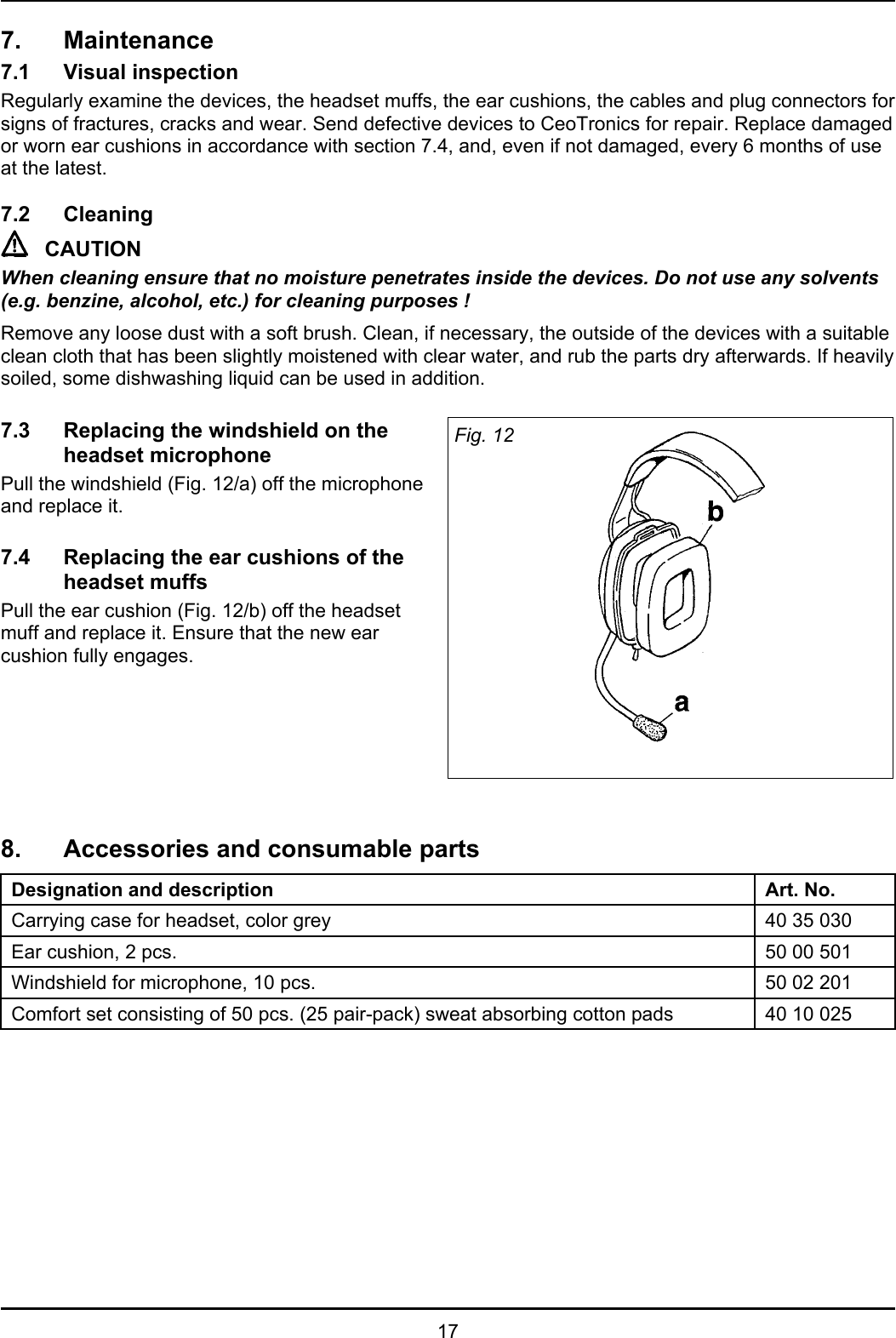
users manual
2.
revised users manual
users manual
Navigation menu
Upload a User Manual
Namespaces
Wiki Guide
HTML
PDF
Info
Views
User Manual
Discussion / Help
Navigation