CeoTronics CT-DECT-I24 CT-DECT-Module User Manual CT GateCom UserMan
CeoTronics AG CT-DECT-Module CT GateCom UserMan
users manual

CT-GateCom II.24
Full duplex communication system for aircraft push-back
Example
Users Manual
Contents
Introduction............................................................................................................................................... 2
1. Important safety instructions ............................................................................................................. 2
2. Description ........................................................................................................................................ 5
2.1 General.......................................................................................................................................... 5
2.2 Communication circuits ................................................................................................................. 5
2.3 System overview ........................................................................................................................... 5
2.4 Aircraft Interface CT-GateCom II.24+4.......................................................................................... 5
2.8 Battery charger .............................................................................................................................. 7
3. Commissioning and operation........................................................................................................... 7
3.1 Aircaft Interface ............................................................................................................................. 7
3.2 Headsets and Transmitter/Receiver Units..................................................................................... 8
3.3 Switching on, adjusting the speaker volume ................................................................................. 8
3.4 Connection setup and release by the Transmitter/Receiver Unit(s) .............................................. 8
3.5 End of operation ............................................................................................................................ 9
4. Safekeeping – storage ...................................................................................................................... 9
5. Recharging the Battery Pack ............................................................................................................ 9
6. Maintenance...................................................................................................................................... 9
6.1 Visual inspections.......................................................................................................................... 9
6.2 Cleaning ........................................................................................................................................ 9
7. On-air subscription.......................................................................................................................... 10
7.1 General........................................................................................................................................ 10
7.2 On-air subscription of the first Transmitter/Receiver Unit of group 1........................................... 11
7.3 On-air subscription of the second Transmitter/Receiver Unit of group 1..................................... 11
7.4 On-air subscription of the first and second Transmitter/Receiver Unit of group 2 ....................... 11

2
Introduction
This user manual is an example and describes the CeoTrionics Aircraft Interface
– that contains the Transceiver Module CT-DECT-I24 – in conjunction with 4 CeoTronics
Transmitter/Receiver Units CT-GateComII.24/Multi provided with CT GroundCom
Headsets.
Important Note
Please note that any changes or modifications not expressly approved by the party
responsible for compliance will void the user’s authority to operate the equipment.
This device complies with part 15 of the FCC Rules. Operation is subject to the following two
conditions: (1) This device may not cause harmful interference, and (2) this device must
accept any interference received, including interference that cause undesired operation.
Declaration concerning RF Radiation Exposure:
The CT-GateCom II.24 contains the transceiver module CT-DECT-I24. The system is
considered to be a mobile transceiver. The safety distance between the mobile device and any
human person must be 20 centimeters (7.9 in.).
1. Important safety instructions
When using CeoTronics products do not fail to comply with the following safety
information:
zBefore using CeoTronics products read completely the appropriate operating instructions. If in doubt,
ask our technical staff.
zIf repair work of any kind needs to be done to CeoTronics products, arrange for it to be performed
only by the company CeoTronics or by a specialized workshop that is authorized by CeoTronics. In
all other cases our warranty and liability for the product shall lapse.
zIf products are operated on a mains voltage, always pull the mains plug out of the mains plug socket
before opening such products (e.g. for servicing purposes) !
zDo not store CeoTronics products outside or in damp ambient conditions. At all times keep them
clean, dry and at normal air humidity. CeoTronics products must not be stored in areas with a
temperature of over +80° C (+176° F), e.g. in the summertime on the parcel shelf of a car. If not
stated otherwise, the following temperature ranges are allowed for CeoTronics products: -10 to
+55° C (+14 to +131° F) for operation, -40 to +80° C (-40 to +176° F) for storage.

3
zDo not immerse a CeoTronics product into water, if it is not expressly specified for this purpose.
zWhen using CeoTronics products that are equipped with connection leads ensure that the latter do
not get caught up in operational machinery or wheels !
zCeoTronics products that are not intrinsically safe (explosion-proof) and therefore have no special
explosion-proof designation must never be operated in potentially explosive environments (e.g.
when refuelling cars, aircraft etc.). Devices that are not explosion-proof can unintentionally trigger off
explosions in such areas !
zConnect CeoTronics accessories to a device or disconnect them from a device only when the device
is switched off.
zIf you are a cardiac pacemaker carrier, before operating a transmitter/receiver ask the manufacturer
of your cardiac pacemaker for information about any impairment that might be caused due to high
frequencies.
zWhen on board an airplane always keep a transmitter/receiver switched off. Operation of the
transmitter/receiver could affect the safety of the airplane and it is therefore prohibited. Never
operate electronic devices on board an airplane without the express approval of an authorized
member of the cabin crew.
zDo not leave CeoTronics products lying around loose in cars, e.g. on the parcel shelf. Stow these
products in a suitable, safe place in the car so that they do not present a danger to you or to other
occupants of the car, if emergency braking is effected.
zCharge rechargeable batteries only with the appropriate suitable CeoTronics charger. Observe the
voltage and currency specifications, including those on the mains face (e.g. 230 V AC or 115 V AC).
Never use the charger to recharge non-rechargeable batteries.
zWhen handling rechargeable batteries comply with environmental protection regulations !
Rechargeable batteries contain toxic chemicals (e.g. cadmium). Never attempt to open a
rechargeable battery and never throw a rechargeable battery into fire. Expended (defective)
rechargeable batteries are subject to compulsory regulated waste disposal. Do not put them in the
household waste !
zEnsure that a short-circuit (risk of fire or injury) is not created across rechargeable battery terminals
or charging sockets by a short-out (bent-open paper clip, bunch of keys etc.). In such an event the
warranty shall lapse. Transport any spare rechargeable batteries in an electrically non-conducting
package in order to avoid short-circuiting the rechargeable batteries.
zKeep CeoTronics products and rechargeable batteries out of the reach of children and any other
persons who are not familiar with the handling and operation thereof.
zPackaging materials, e.g. filling materials and plastic bags are not toys and have to be kept out of
the reach of children. There is a risk of children ingesting them and choking !
zSafe operation requires clean devices. Ensure that the devices are clean and in good condition at all
times.
zCeoTronics products may only be used for the specific application envisaged.
zIf the device is to be put out of operation definitively, bring it to a local recycling plant for disposal or
send it to CeoTronics.
4
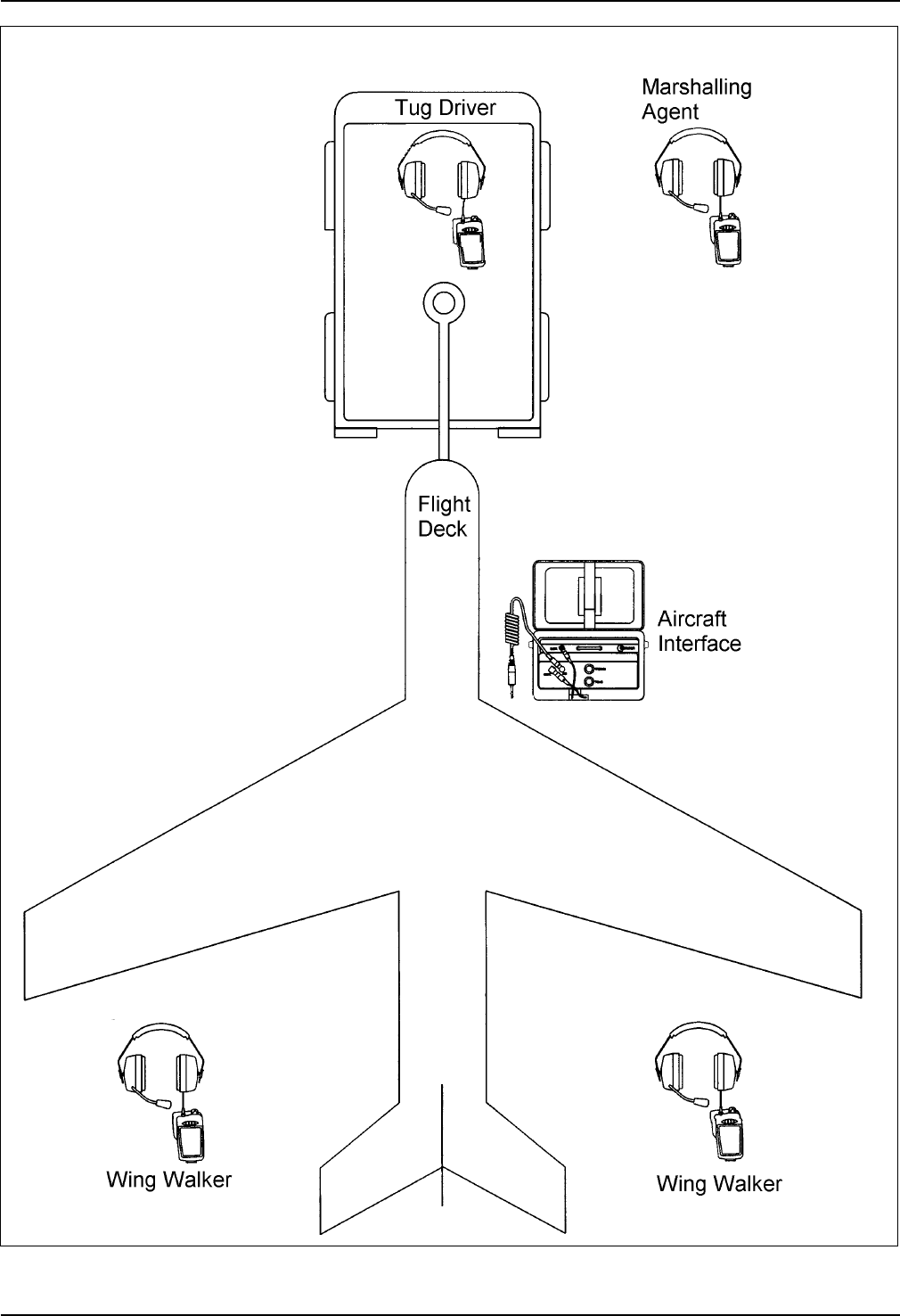
Fig. 1 System overview (example)

5
2. Description
2.1 General
This duplex communication system (see example Fig. 1) is used for aircraft push-back. The tug driver,
two wing walkers and marshalling agent wear headsets in conjunction with Transmitter/Receiver Units
»CT-GateCom II.24/Multi«. The four headset wearers outside the aircraft can communicate with one
another. The tug driver is able to communicate with the flight deck via the Aircraft Interface that is
connected to the aircraft intercom on the outside of the aircraft.
The Aircraft Interface contains the Transceiver Module CT-DECT-I24.
The range depends on the local circumstances. Protection against eavesdropping is ensured by the
digital design. Channel selection is effected automatically.
2.2 Communication circuits
Wing walkers
The two wing walkers can communicate with each other, with the marshalling agent, and with the tug
driver. The wing walkers are not able to speak to the flight deck. But they are able to hear the
communication between the flight deck and the tug driver.
Marshalling agent
The marshalling agent can communicate with the two wing walkers and with the tug driver. He is able to
hear the communication between the flight deck and the tug driver. When the tug driver speakes to the
flight deck the marshalling agent can also speak to the flight deck as long as the microphone switch at
the left headset muff of the tug driver is in position »PTT« or »HOT«.
Tug driver
The tug driver can communicate with the two wing walkers, with the marshalling agent, and with the
flight deck. When he communicates with the wing walkers and/or with the marshalling agent the flight
deck doesn‘t hear this communication. When the tug driver communicates with the flight deck the two
wing walkers and the marshalling agent will hear this communication also.
The tug driver is the only person who is able to control the communication with the flight deck.
Flight deck
The flight deck can only communicate with the tug driver. The two wing walkers and the marshalling
agent can hear this communication as well. When the tug driver speakes to the flight deck the
marshalling agent can also speak to the flight deck as long as the microphone switch at the left headset
muff of the tug driver is in position »PTT« or »HOT«.
2.3 System overview
The system (see example Fig. 1) consists of:
yone Aircraft Interface CT-GateCom II.24+4 that contains the Transceiver Module CT-DECT-I24
yone single-unit charger for the Li-Ion rechargeable battery 3.6 V/2300 mAh in the Battery Pack of the
Aircraft Interface CT-GateCom II.24+4
yfour Transmitter/Receiver Units CT-GateCom II.24/Multi provided with four GroundCom Headsets
2.4 Aircraft Interface CT-GateCom II.24+4
The Aircraft Interface (Fig. 2) consists of Interface (Fig. 2/j) and Battery Pack (Fig. 2/c) which reside in a
carrying bag (Fig. 2/a). The Transceiver Module CT-DECT-I24 is integrated in the Aircraft Interface.
The carrying bag is closed by means of a zip. The unit is connected to the aircraft intercom via
connecting cable and male jack-plug (Fig. 2/k).
The Battery Pack contains a Li-Ion rechargeable battery 3.6 V/2300 mAh. It supplies the power for the
Interface. The Battery Pack can be charged via the charging socket (Fig. 2/d).
6
The weatherproof carrying bag is used to stow the Interface and the Battery Pack and can be attached
to the aircraft, e.g. the access cover for the aircraft intercom, by means of the carrying strap or a hook.
Î NOTE
zKeep the carrying bag closed when in use.
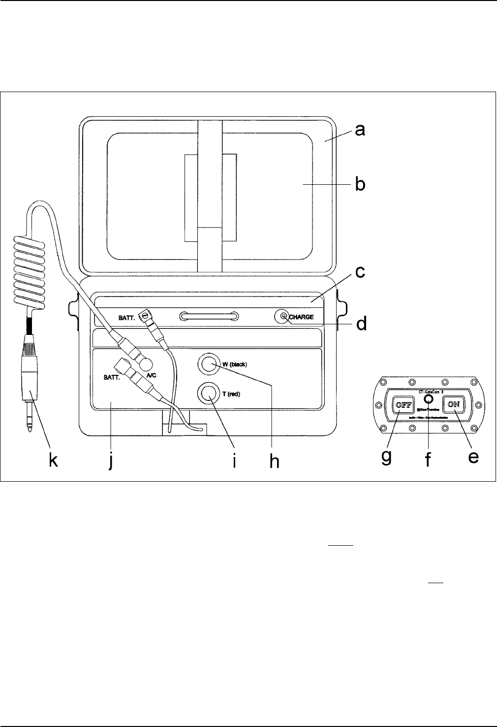
Fig. 2 CT-GateCom II.24+4/Aircraft Interface
a Carrying bag for the Interface and the Battery
Pack
b Stowage place for the coiled connecting cable
(item »k«)
c Battery Pack for the Interface. Equipped with a
Li-Ion rechargeable battery 3.6 V/2300 mAh in
the unit
d Charging socket »CHARGE« for the Li-Ion
rechargeable battery 3.6 V/2300 mAh in the
Battery Pack
e Green push-button »ON« to switch on the unit
f Control lamp, lights up if the unit is switched on,
flashes if the Battery Pack voltage is too low
g Red push-button »OFF« to switch off the unit
h Black subscription button »W« for the
Transmitter/Receiver Units group 2 for wing
walkers with black colored push-button bank
i Red subscription button »R« for the
Transmitter/Receiver Units group 1 for tug
driver and marshalling agent with red colored
push-button bank
j Interface
k Coiled connecting cable with male jack-plug for
connection to the aircraft intercom
7
2.8 Battery charger
The rechargeable Li-Ion battery 3.6 V/2300 mAh in the Battery Pack of the Aircraft Interface should only
be charged with the charger supplied with the system (see section 2.3). For recharging the battey see
section 5 and the special CeoTronics users manual for the charger.
3. Commissioning and operation
Î NOTE
In the following the commissioning and operation of the system is described for the Aircraft
Interface and the Transmitter/Receiver Units CT-GateCom II.24/Multi which are used in
conjunction with communication headsets. The Aircraft Interface contains the Transceiver
Module CT-DECT-I24.
3.1 Aircaft Interface
The rechargeable battery in the Battery Pack must be fully charged.
a. Open the carrying bag for the Aircraft Interface by means of the zip.
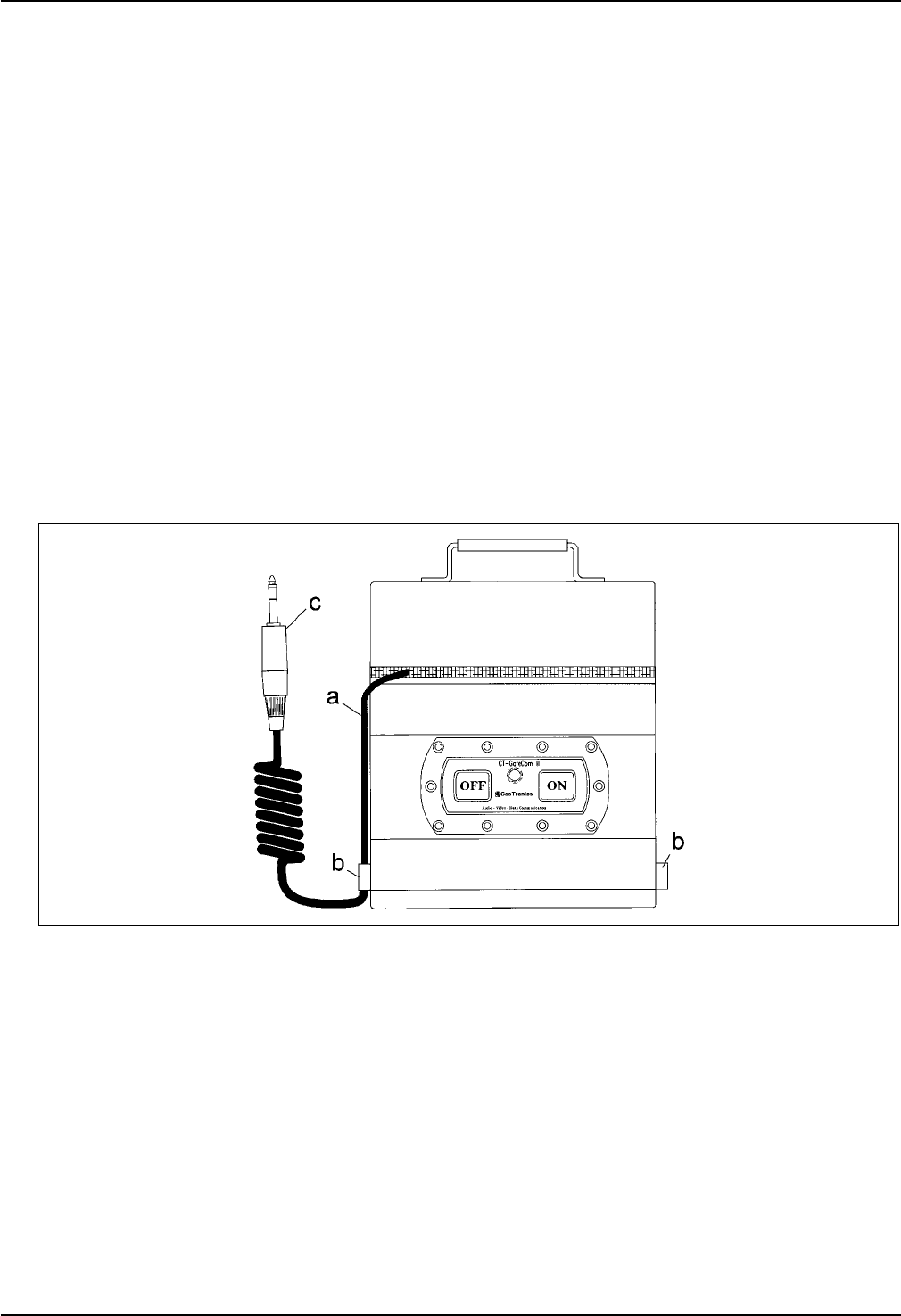
b. Take the connecting cable (Fig. 3/a) with male jack-plug (Fig. 3/c) out of the cover of the carrying
bag. Lead the connecting cable with male jack-plug through one of the loops (Fig. 3/b) on the
carrying bag. Close the carrying bag by means of the zip. This prevents any fluids running along
the lead into the carrying bag.
Fig. 3
c. At the aircraft locate the aircraft intercom connector. Hang the carrying bag e.g. over the access
cover or to a suitable place near the aircraft intercom connector by means of the carrying strap or by
means of a hook.
Connect the Aircraft Interface via the connection cable and the male jack-plug to the female jack-
plug for the aircraft intercom.
Î NOTE
Keep the carrying bag for the Aircraft Interface closed at all times while in use!

8
3.2 Headsets and Transmitter/Receiver Units
Connect the headset via the connecting cable and plug to its Transmitter/Receiver Unit. Fasten the
Transmitter/Receiver Unit by means of the clip on the rear to a suitable place on your clothing. Put on
the headset.
3.3 Switching on, adjusting the speaker volume
Î NOTES
zThe Aircraft Interface must always be switched on before the Transmitter/Receiver Units.
zOn the Transmitter/Receiver Units the push-buttons for connection setup and connection
release, placed in the middle of the push-button bank, must not be pressed until the
Transmitter/Receiver Units are synchronized with the Aircraft Interface.
zAlways leave the Aircraft Interface and the Transmitter/Receiver Units switched on as long as
you work with the communication system so that immediate availability of the system is
provided.
a. First switch on the Aircraft Interface by means of the green push-button ON (Fig. 2/e). The control
lamp (Fig. 2/f) illuminates. If the Battery Pack voltage is too low the control lamp flashes and the
Battery Pack must be charged.
b. Switch on the Transmitter/Receiver Unit by means of the On/Off switch and volume control (rotary
knob).
After Switching on the connection synchronization between Transmitter/Receiver Unit and Aircraft
Interface is effected automatically.
Synchronization: A click is audible in the headset connected to the Transmitter/Receiver Unit
approximately 10 seconds after switching on. The synchronization procedure then begins, i.e. the
previously switched on Aircraft Interface seeks its Transmitter/Receiver Unit. This synchronization
procedure can last approx. 30 seconds. Upon completion of synchronization – i.e. the Aircraft
Interface has found its Transmitter/Receiver Unit – a high double-beep P-tone sounds in the
headset, indicating that the Transmitter/Receiver Unit and the Aircraft Interface are ready for
operation.
c. At the Transmitter/Receiver Unit set the On/Off switch and volume control (rotary knob) to mid-
position. Later, on voice reception, adjust the desired speaker volume for your headset. Do not set
the volume any higher than necessary.
d. Connection setup and release by the Transmitter/Receiver Units see sections 3.4...3.4.2.
3.4 Connection setup and release by the Transmitter/Receiver Unit(s)
3.4.1 Prerequisites
yAircraft Interface and Transmitter/Receiver Unit(s) subscribed (sections 7...7.4)
yAircraft Interface and Transmitter/Receiver Unit(s) switched on and synchronized (section 3.3)
3.4.2 Connection setup and release
Automatic connection setup after switching on
After the Aircraft Interface and the Transmitter/Receiver Unit(s) are switched on the connection
synchronization between the the Aircraft Interface and the Transmitter/Receiver Unit(s) is(are) effected
automatically. Subsequently communication is possible.
Connection release
Briefly press one of the push-buttons for connection setup and release in the middle of the push-button
bank at the Transmitter/Receiver Unit. The Transmitter/Receiver Unit is disconnected from the Aircraft
Interface. This procedure is acknowleded by a high beep P-tone in the headset connected to the
Transmitter/Receiver Unit.

9
Reconnection
Briefly press one of the push-buttons for connection setup and release in the middle of the push-button
bank at the Transmitter/Receiver Unit. In the headset connected to the Transmitter/Receiver Unit a high
beep P-tone sounds when the connection is set up between the Transmitter/Reciever Unit and the
Aircraft Interface.
3.5 End of operation
At the end of the workshift, switch off the Aircraft Interface before any of the Transmitter/Receiver Units.
Recharge the rechargeable battery in the Battery Pack.
4. Safekeeping – storage
Store the cleaned devices in a clean, dry place at normal room temperature and in normal relative air
humidity.
5. Recharging the Battery Pack
The rechargeable Li-Ion battery 3.6 V/2300 mAh in the Battery Pack of the Aircraft Interface should only
be charged with the charger supplied with the system (see section 2.3). Otherwise the battery may be
damaged. The charger is neither water-tight nor dust-tight. Protect it against water, rain and dirt. The
charger may only be used in rooms with normal relative air humidity and temperature. Do not cover up
the ventilation slots of the charger.
CAUTION
Never use battery chargers to charge non-rechargeable batteries. Never open rechargeable
batteries or throw them into fire. Used (defective) rechargeable batteries are subject to special
waste disposal. Do not put them in the household refuse. Observe your local regulations !
CAUTION
Never charge a rechargeable battery in areas with an explosion risk – an explosion may result.
Charge and change rechargeable batteries only within a building or similar environment that
does not contain dangerous concentrations of volatile vapors.
Notice the special CeoTronics users manual for the charger.
To charge the battery pack, switch off the unit by means of the red push-button OFF (Fig. 2/g).
6. Maintenance
6.1 Visual inspections
Regularly examine the device, the cables and plug connectors for signs of fractures, cracks and wear.
Send a defective device to CeoTronics for repair.
6.2 Cleaning
CAUTION
When cleaning ensure that no moisture penetrates inside the devices. Do not use any solvents
(e.g. benzine, alcohol, etc.) for cleaning purposes !
Remove any loose dust with a soft brush. Clean, if necessary, the outside of the devices with a suitable
clean cloth that has been slightly moistened with clear water, and rub the parts dry afterwards. If heavily
soiled, some dishwashing liquid can be used in addition. Clean connectors with a commonly available
contact cleaning agent.

10
7. On-air subscription
7.1 General
Î NOTES
zThe on-air subscription is a procedure which has to be performed once only ex-works.
It must be performed again only in the case of an error or if another Transmitter/Receiver Unit
CT-GateCom II.24 will be used in conjunction with the Aircraft Interface. The Aircraft Interface
contains the Transceiver Module CT-DECT-I24.
zIn the following the on-air subscription is described for the Aircraft Interface in conjunction
with Transmitter/Receiver Units CT-GateCom II.24/Multi. The on-air subscription for the
Aircraft Interface in conjunction with Transmitter/Receiver Headsets CT-GateCom II.24 is
carried out analogous and in the sequence as described in sections 7.2...7.4.
The subscription procedure is performed on the Aircraft Interface and the Transmitter/Receiver Units
manually by means of a procedure carried out by the operator.
The Aircraft Interface is equipped with two radio modules. The four Transmitter/Receiver Units are
equipped with one radio module each. Each unit (radio module) has its own identification number.
A max. of four Transmitter/Receiver Units (in two groups) is allocated to the two radio modules in the
Aircraft Interface. The Aircraft Interface is the base unit and the Transmitter/Receiver Units are
subscribed to the Aircraft Interface. First of all an allocation must always take place between the Aircraft
Interface and the Transmitter/Receiver Units.
Ex-works the four Transmitter/Receiver Units are divided in two groups as follows
(Fig. 2/i and h):
yGroup 1 – Transmitter/Receiver Units with red colored push-button bank for tug driver and
marshalling agent. The subscription is carried out by means of the red subscription button
»T« (Fig. 2/i) for group 1 at the Aircraft Interface
yGroup 2 – Transmitter/Receiver Units with black colored push-button bank for wing walkers.
The subscription is carried out by means of the black subscription button »W« (Fig. 2/h) for
group 2 at the Aircraft Interface
Other allocations in pairs can be carried out later by the customer. Please heed that the subscription of
the Transmitter/Receiver Units in conjunction with the Aircraft Interface is always carried out in pairs.
If a third Transmitter/Receiver Unit is subscribed to one of the two groups of the the Aircraft Interface,
the Transmitter/Receiver Unit that was subscribed first is deleted from the data base of the Aircraft
Interface.
Once the subscription procedure has been successfully concluded, the identity of the communication
partners is stored in the data base of the Aircraft Interface and of the Transmitter/Receiver Units. A
Transmitter/Receiver Unit stores one Aircraft Interface, the Aircraft Interface stores in pairs up to four
(2 x 2) Transmitter/Receiver Units.
Time Out
If the Aircraft Interface or a Transmitter/Receiver Unit is set to subscription mode and this is terminated
or not completed after 2 minutes without the subscription procedure having been successfully
concluded a »Time Out« occurs. The »Time Out« effects that in the Aircraft Interface the available data
bases for a max. of two stored Transmitter/Receiver Units of a group and in the case of the
Transmitter/Receiver Unit the available data base for the stored Aircraft Interface are deleted. After a
»Time Out« the subscription procedure for the Aircraft Interface and for both Transmitter/Receiver Units
must be restarted.

11
7.2 On-air subscription of the first Transmitter/Receiver Unit of group 1
Î NOTE
zThe Transmitter/Receiver Units are subscribed in pairs (group 1 and 2 see section 1), but one
after the other, to the Aircraft Interface. First the two Transmitter/Receiver Units of group 1
are subscribed one after the other to the Aircraft Interface and then the two
Transmitter/Receiver Units of group 2 are subscribed one after the other to the Aircraft
Interface.
zTwo Transmitter/Receiver Units can never be simultaneously subscribed to the Aircraft
Interface. The Transmitter/Receiver Units must always be subscribed one after the other to
complete a group.
zFor subscription the Aircraft Interface must always be switched on before the
Transmitter/Receiver Unit.
a. Connect the first headset of group 1 to the first Transmitter/Receiver Unit of group 1 (identifiable by
the red colored push-button bank) via the connecting cable and plug of the headset. Open the
carrying bag for the Aircraft Interface by means of the zip.
b. At the Aircraft Interface press the red subscription push-button »T« (Fig. 2/i) for group 1, keep the
red push-button »T« pressed and switch on the Aircraft Interface by means of the green push-button
ON (Fig. 2/e). The control lamp (Fig. 2/f) illuminates. After switching on keep the red subscription
push-button »T« pressed for at least 10 seconds. Than immediately carry out step »c«.
c. At the first Transmitter/Receiver Unit group 1 with red colored push-button bank press the
subscription button 1 simultaneous with subscription button 5 located at the begin and end of the
push-button bank. Keep the two push-buttons pressed and switch on the Transmitter/Receiver Unit
by means of the On/Off switch and volume control (rotary knob). After switching on keep the two
push-buttons pressed for at least 10 seconds.
The subscription procedure on the Transmitter/Receiver Unit has to be started within 2
minutes after the subscription procedure on the Aircraft Interface was started, otherwise a
»Time Out« may occur (see section 7.1).
After approx. 30 seconds a high double-beep tone can be heard in the headset. This indicates that
the on-air subscription has been successfully completed. A second high double-beep tone finally
reports that the Transmitter/Receiver Unit has synchronized itself with the Aircraft Interface.
7.3 On-air subscription of the second Transmitter/Receiver Unit of group 1
a. Switch off the Aircraft Interface with the red push-button OFF (Fig. 2/g). The control lamp (Fig. 2/f)
extinguishes.
b. Connect the second headset of group 1 to the second Transmitter/Receiver Unit of group 1
(identifiable by the red colored push-button bank) by means of the connecting cable and plug of the
headset. Ensure that the Transmitter/Receiver Unit is switched off. The on/off switch and volume
control (rotary knob) must be set to OFF .
c. Repeat the subscription procedure for the Aircraft Interface and the second Transmitter/Receiver
Unit of group 1 as described in section 7.2, steps »b« and »c«, for the Aircraft Interface and for the
first Transmitter/Receiver Unit of group 1.
7.4 On-air subscription of the first and second Transmitter/Receiver Unit of group 2
The subscription procedure for the Aircraft Interface and the two Transmitter/receiver Units of group 2
(identifiable by the black colored push-button bank) is carried out as described in sections 7.2 and 7.3
for the two Transmitter/Receiver Units of group 1. At the Aircraft Interface the black subscription push-
button »W« (Fig. 2/h) for group 2 is used instead of the red push-button »T« for group 1 (Fig. 2/i).

Germany and
International Sales
CeoTronics AG
Adam-Opel-Str. 6
63322 Rödermark (Germany)
Tel. +49-(0) 6074/87 51-0
Fax +49-(0) 6074/87 51-676
E-Mail verkauf@ceotronics.com
USA/Canada/Mexico
CeoTronics, Inc.
533 Byron Street, Suite E
Chesapeake, VA 23320-6603
Tel. (757) 549-6220
Fax (757) 549-6230
E-Mail sales@ceotronicsusa.com
Great Britain and Ireland
CeoTronics Ltd.
1 Highview y High Street
BORDON, Hampshire
GU35 0AX
Tel. 01420-47 93 53
Fax 01420-47 93 72
E-Mail ceotronics@winweb.com
France
CeoTronics Sarl
Z.A. des Arpents
16, Rue du Pré aux Aulnes
77340 PONTAULT-COMBAULT
Téléphone 01 60 18 33 00
Télécopie 01 60 28 60 60
E-Mail ceotronics@worldonline.fr
Spain
CeoTronics S.L.
C/Antonio Vicent 23-1°
28019 Madrid
Tel. 91-460 82 50/51
Fax 91-460 31 93
E-Mail
ceotronics.gil@mad.canalpyme.com
Switzerland
CeoTronics AG
Grundstr. 16
6343 Rotkreuz
Tel. 041/790 58 38
Fax 041/790 58 39
E-Mail ceotronics@tic.ch
EIGENE/CT-GATECOMII/ZUL-USA-2.DOC/02/0102 y DOK 0357 Subject to change
Copyright © 1/2002 CeoTronics AG, 63322 Rödermark, Germany, Internet www.ceotronics.com

Federal Communications Commission
Authorization and Evaluation Division
Equipment Authorization Branch
7435 Oakland Mills Road
Columbia, MD 21046
January 31, 2002
Applicant’s declaration concerning RF Radiation Exposure
We hereby indicate that the product
CT-DECT-I24
is considered to be a mobile transceiver.
A safety distance of 20 centimeter (7.9 inch) between the Dect-module and human
person must be ensured.
The output power is maximum +20.6 dBm.
This device and its antenna must not be co-located or operating in conjunction with any
other antenna or transmitter.
A safety statement will be integrated in the user’s manual to provide end-users with
transmitter operating instructions for satisfying RF exposure compliance.
CeoTronics AG
Adam Opel Strasse 6
D- 63322 Rödermark
Germany
Rödermark, January 31, 2002
Berthold Hemer
Member of board R & D