CeoTronics CT-RXRCD9007 CT-ClipCom digital SD User Manual dok1368 be
CeoTronics AG CT-ClipCom digital SD dok1368 be
User Manual
Communication set In-Ear with ambient
sound reception (CT-ClipCom Digital)
Operation instructions
1
English

2
Content
1. Important safety instructions .............................................................................................................. 3
2. Description ......................................................................................................................................... 4
2.1 Ear-microphone .......................................................................................................................... 6
2.2 Earphone with gooseneck-microphone....................................................................................... 6
2.3 Universal three level ear plug ..................................................................................................... 7
2.4 Individually ear mould ................................................................................................................. 7
2.5 PTT-button ................................................................................................................................ 11
2.6 CT-Wireless-PTT (example) ..................................................................................................... 12
3. Commissioning and operation ......................................................................................................... 14
4. Safekeeping – storage ..................................................................................................................... 15
5. Maintenance .................................................................................................................................... 15
5.1 Visual inspections ..................................................................................................................... 15
5.2 Cleaning .................................................................................................................................... 15
5.3 Changing the protective cover of the gooseneck microphone .................................................. 16
6. Consumable parts + accessory ........................................................................................................ 16

3
1. Important safety instructions
For the use of the device notice the national safety and accident prevention
regulations and the following safety instructions shown in italics in this instruction
manual.
z Before using CeoTronics products read completely the appropriate operating instructions. If in doubt,
ask our technical staff.
z Use only CeoTronics products without damage and wear.
z If repair work of any kind needs to be done to CeoTronics products, arrange for it to be performed
only by the company CeoTronics or by a specialized workshop that is authorized by CeoTronics. In
all other cases our warranty and liability for the product shall lapse.
z Do not store CeoTronics products outside or in damp ambient conditions. At all times keep them
clean, dry and at normal air humidity. CeoTronics products must not be stored in areas with a
temperature of over +80° C (+176° F), e.g. in the summertime on the parcel shelf of a car. If not
stated otherwise, the following temperature ranges are allowed for CeoTronics products: -10 to
+55° C (+14 to +131° F) for operation, -40 to +80° C (-40 to +176° F) for storage.
z Do not immerse a CeoTronics product into water, if it is not expressly specified for this purpose.
z When using CeoTronics products that are equipped with connection leads ensure that the latter do
not get caught up in operational machinery or wheels!
z CeoTronics products that are not intrinsically safe (explosion-proof) and therefore have no special
explosion-proof designation must never be operated in potentially explosive environments (e.g.
when refuelling cars, aircraft etc.). Devices that are not explosion-proof can unintentionally trigger off
explosions in such areas!
z Connect CeoTronics accessories to a device or disconnect them from a device only when the device
is switched off. In the case of intrinsically safe products (explosion-proof) this must always take place
outside of the potentially explosive area. Otherwise the consequence could be an unintentional
explosion!
z Please note that in some radios very loud signalling beeps could be present already in the
moment of switching the radio on. There are various types of radios generating a series of
signals in different loudness levels. It may be necessary to adjust the volume of the
signalling beeps separately. These beeps could damage your hearing if they are set too high.
Therefore, adjust signalling beeps to a convenient level as desired before starting to use
CeoTronics accessories. Follow the instructions of the radio manufacturer’s operating
manual to adjust the signalling beeps.
z For safety reasons reception volumes in excess of 85 dB (A) are possible with a whole series of
CeoTronics products. However, these can be regulated by the user. After switching on the
communication system, set the reception volume to approx. 1/2 the available loudness volume and
then test the audible volume, e.g. by opening the squelch on the radio set.
Do not set the volume any higher than is necessary. A very high volume setting can lead to
damaged hearing, particularly if it is continuous. For high volumes or noise levels wear additional ear
plugs. If in doubt, ask your safety officer or company doctor.
z Do not leave CeoTronics products lying around loose in cars, e.g. on the parcel shelf. Stow these
products in a suitable, safe place in the car so that they do not present a danger to you or to other
occupants of the car, if emergency braking is effected.
z Keep CeoTronics products out of the reach of children and any other persons who are not familiar
with the handling and operation thereof.
z Packaging materials, e.g. filling materials and plastic bags are not toys and have to be kept out of
the reach of children. There is a risk of children ingesting them and choking!
z Safe operation requires clean devices. Ensure that the devices (microphones, connectors etc.) are
clean and in good condition at all times.
z CeoTronics products may only be used for the specific application envisaged.

4
z Should equipment, supplied by CeoTronics, be definitely put out of service you may return it to
CeoTronics. We ensure recycling and/or disposal of outdated equipment in compliance with
the applicable environment protection law.
z Keep these operating instructions for later use.
2. Description
General
The CT-ClipCom Digital is a binaural communication system for use with radio equipment. The PTT
buttons (PTT=push-to-talk) of the system are used to transmit PTT commands to the radio unit or
similar communication systems.
The following two system configurations are available:
CT-ClipCom Digital ear microphone consisting of one ear microphones plus one earphone, a PTT
transmit button, and an optional CT-Wireless-PTT
CT-ClipCom Digital gooseneck microphone consisting of one earphone plus one earphone with
gooseneck microphone, a PTT transmit button, and an optional CT-Wireless-PTT
The earphones/ear microphones are electro-acoustic transducers, used either as microphones (for
transmitting) or earphones (for receiving), worn in the ear with ear plugs.
Optional can be worn the ear microphone in the ear with individually formed ear moulds.
The system is equipped with ambient sound reception (ASR) for both sides.
The employment of ASR makes a level-dependant sound absorption possible.
Power is provided by the radio unit.
5
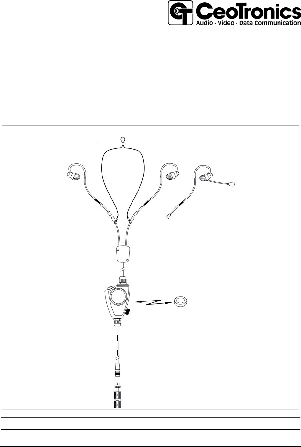
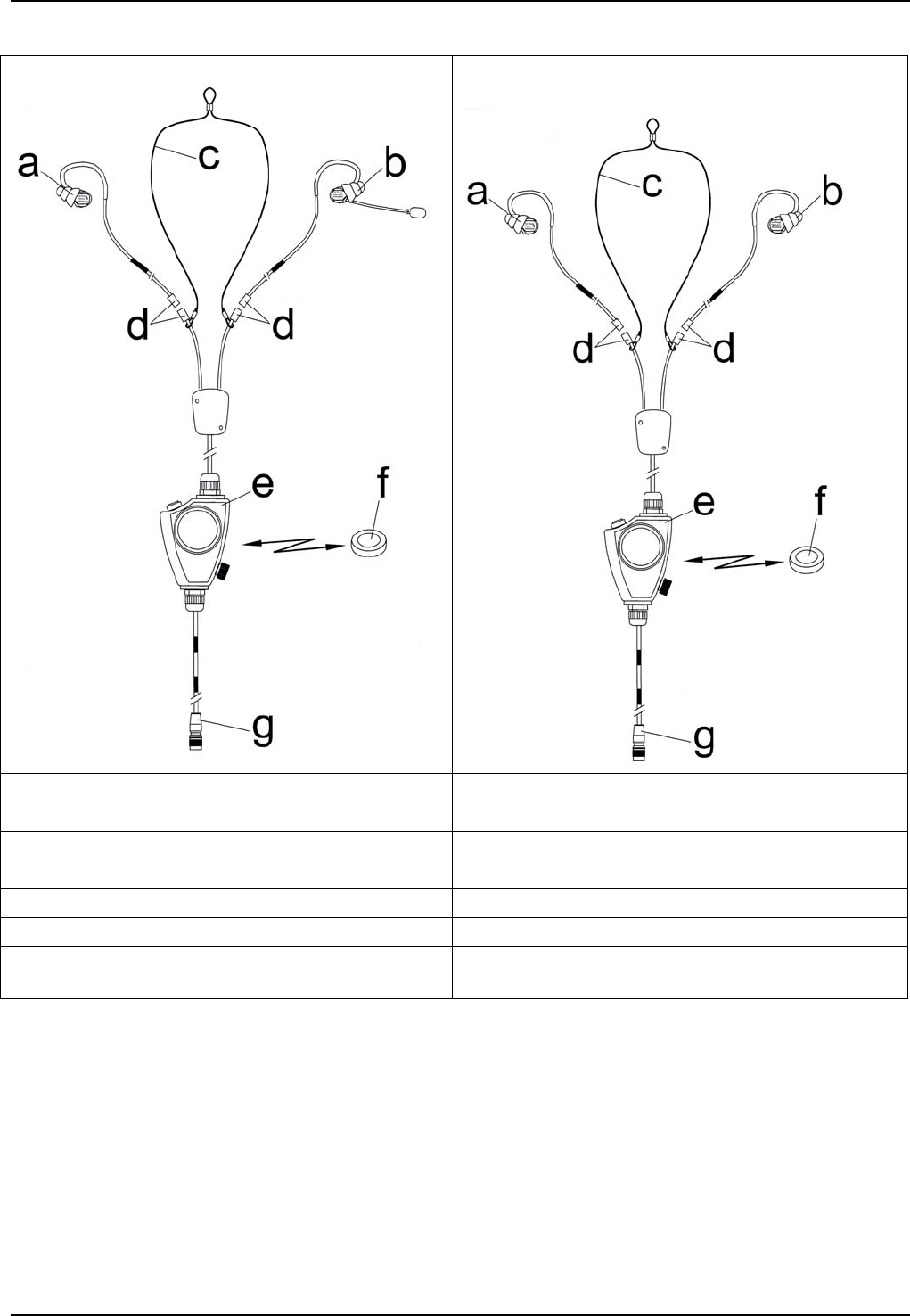
System overview (examples)
2 CT-ClipCom Digital gooseneck microphone
3 ClipCom Digital ear-microphone
a ear-phone a ear-microphone
b ear-phone with gooseneck microphone b ear-phone
c neck band c neck band
d connector d connector
e PTT-button d PTT-button
f CT-Wireless-PTT (example) e CT-Wireless-PTT (example)
g connection plug for radio (example –
dependant on the radio)
g connection plug for radio (example –
dependant on the radio)
6
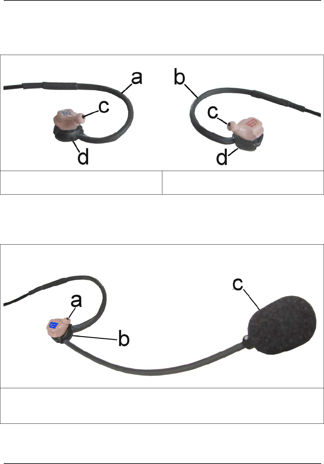
2.1 Ear-microphone
The ear-microphone is at the right side and is identified by a red marking. The earphone is at the left
side and is identified by a blue marking. The casing of the ear-microphone contains the ASR-
microphone (figure 4/d) in addition to the ear-microphone itself (figure 4/c).
For using the ear-microphone it is just clipped onto the ear plug (see 2.3).
4
a ear-phone left
c ear-microphone and earphone
b ear-microphone right
d ASR-microphone
2.2 Earphone with gooseneck-microphone
The earphone with gooseneck microphone is available for the left ear only. Gooseneck microphone with
protective cover (figure 5/c) and ASR-microphone (figure 5/b) are attached to the earphone.
For using the earphone it is clipped onto an individual ear plug.
5
a earphone
b ASR-microphone
c gooseneck-microphone with windshield
7
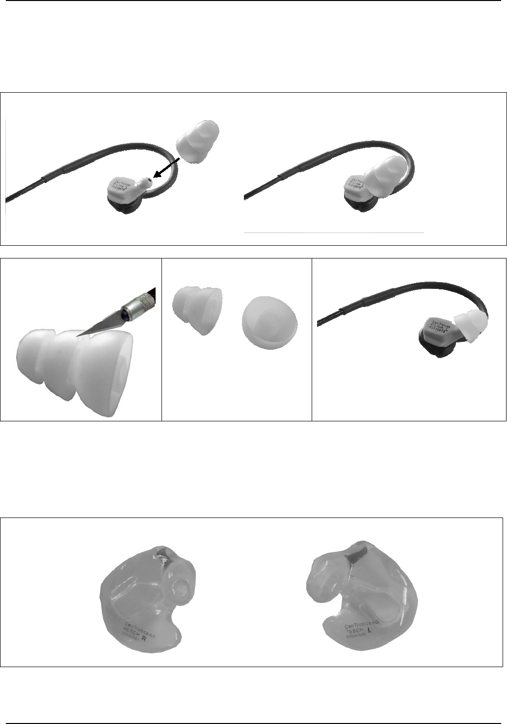
2.3 Universal three level ear plug
The ear plug is used for adaptation of the ear microphone / earphone to the auditory canal. It is
»pushed« with a rotating motion onto the ear microphone / earphone (Fig. 6). If no perfect seat in the
ear is achievable, because the standard ear plug is too large, the largest lamella ring can be cut off with
a sharp knife (figure 7-9).
6
7
8
9
2.4 Individually ear mould
This ear mould (example Fig. 10) ensures maximum wear comfort and transmission quality. Only when
carry the individually ear moulds the highest possible protection of the ears is ensured. It is moulded
according to an individual impression of the auditory canal either for wearing in the right ear or in the left
ear. For different personal needs different variants are available. The earphone is “clipped” in the ear
mould. The ear mould is worn in the ear.
10 right ear mould left ear mould
8
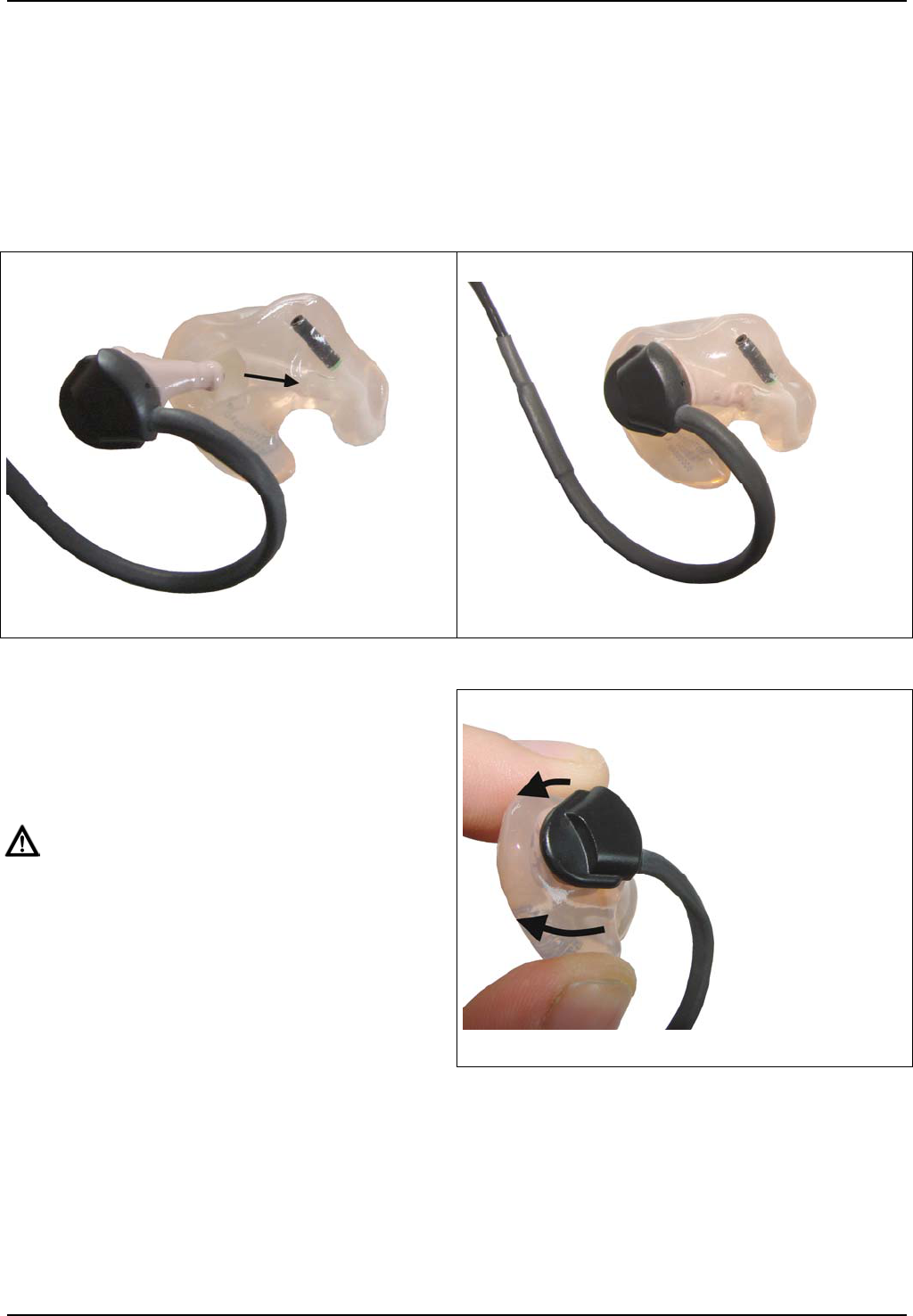
Installing the ear phone in the ear mould
Î PLEASE NOTE
Earphone and ear mould for the right ear have a red ink marking, the ear microphone and ear
mould for the left ear are marked with blue ink.
a. Take the ear mould in one and the ear microphone in the other hand. The sound channels of ear
mould and ear microphone must be looking into the same direction (figure 11).
b. Push the ear microphone in direction of the arrow into the ear mould until it “engages”.
Figure 12 shows the ear microphone inserted in the ear mould.
11
12
Removing the earphone from the ear mould
a. Take the ear mould in one hand and press the
two ends of it against each other (figure 13)
until ear microphone "disengages" from the
ear mould.
ATTENTION!
Never extract the earphone from the ear mould
by pulling the cable.
b. Now hold the earphone with the other hand
and pull it out of the ear mould.
13

9
2.4.1 Information regarding hearing protection (Only for operation with individually ear moulds
with filter SKLD26)
Manufacturer: CeoTronics AG
Type designations: CT-ClipCom digital BoomMike and/or EarMike with p/n 6015068, 6015069 &
options
2.4.1.1 Fitting accuracy of ear moulds
The CT-ClipCom digital communication system combined with personalised ear moulds / earpieces is
considered a personalised hearing protector which has been tested and certified within the scope of the
EC-type approval as personal protection equipment in the meaning of the European Directive
89/686/EG.
The sound insulating effect of a personalised ear mould depends principally on the proper accurate fit
and the personal ergonomics of the user.
For this reason, CeoTronics recommends to check the fitting accuracy of personalised ear moulds by
making acoustic measurements. Only this way it is possible to assure an appropriate sound insulating
effect of your ear mould.
For this purpose CeoTronics has developed a special testing system.
A sound insulation measurement made by this testing system, duly documented by a test certificate,
proves that the personalised ear moulds provide sufficient sound insulation.
Please note that this is a qualitative measurement and therefore the results must not necessarily
coincide with statistically ascertained values of subjective sound insulation experienced by 16 test
persons in the type approval test, as these are two different measuring methods.
Experience shows that that actual personal sound insulation values are slightly higher than the values
measured by the CeoTronics testing system. As the lower limits are used the minimum sound insulation
values of the EN 352-2 Standard.
In rare individual cases it is possible that no satisfactory sound insulation can be achieved in spite of
maximum care exercised in the process of taking impressions and manufacturing the ear moulds.
In such cases our earplugs can be used, however no specific certification is available for use together
with the CT-ClipCom digital communication system.
Wear of ear moulds varies individually; we recommend regular examination by measuring the moulds
with the CeoTronics testing system or replacement of your personalised ear mould after 2 years.
Kindly contact our customer consultants in case you want to test your personalised ear mould or clarify
any further questions regarding this subject.
2.4.1.2 Conformity to Standards
This hearing protection complies with the requirements of the European Standard EN 352-2 and EN
352-7:2003. It has been designed, manufactured, and tested according to the state of the art and in
compliance with the DIN EN ISO 9001 Standard.
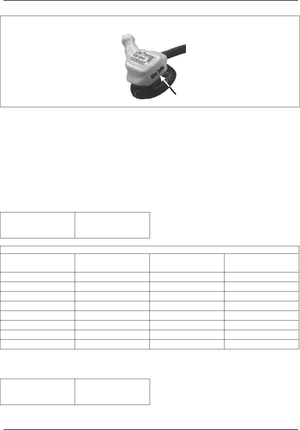
10
Marking:
14 Example
2.4.1.3 General technical data
Mass
BoomMike: ≈17g
EarMike: ≈ 6g
2.4.1.4 Sound insulation values with personalised ear moulds and SKLD26 filter
Please take note that the certified ear moulds / earpieces and earplugs are able to function as hearing
protection only if they are worn on both sides and both are covered by a CT-ClipCom system.
For the one-sided version the sound insulation values of the table below may be used, provided that the
other ear is covered with a sufficient sound insulation.
Sound insulation of the personalised ear moulds and SKLD26 filter
H = 27 dB
M = 22 dB
L = 21 dB
SNR = 26 dB
Result
Frequency
[Hz]
Sound insulation
[dB]
Standard deviation
[dB]
APV
[dB]
63 26,0 6,5 19,5
125 28,0 8,7 19,3
250 26,2 5,8 20,4
500 25,4 5,3 20,1
1000 25,6 4,7 20,9
2000 32,5 5,1 27,4
4000 35,6 3,5 32,1
8000 32,4 6,0 26,4
Level dependence with personalised ear moulds and SKLD26 filter
Criterion level
BoomMike EarMike
H = 102,3 dB
M = 102 dB
L = 109,6 dB
H = 98,8 dB
M = 99 dB
L = 111,8 dB
The APV, H, M, L, and SNR values have been established according to EN ISO 4869-2 with parameter
α=1.
11
2.4.1.5 Output sound pressure level
The CT-ClipCom digital is equipped with a communication system. The user should verify proper
functioning before using it. In case distortions or breakdowns are detected, the user is requested to
follow the manufacturer’s maintenance recommendations.
WARNING! The output sound pressure level of the communication system of the “CT-ClipCom
digital” could exceed the daily limit value.
2.5 PTT-button
The PTT button is provided with connecting cable and plug for connection to a radio unit via a radio
adapter.
The PTT button and the CT-Wireless-PTT have equality of function. The CT-Wireless-PTT must be
subscribed to the PTT button.
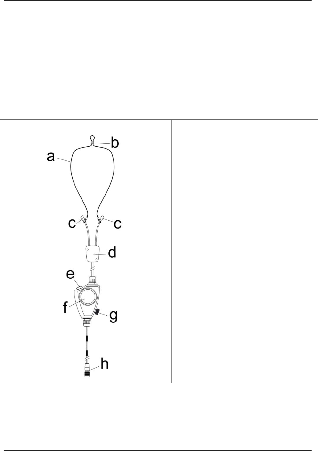
15
a Neck band
b Size regulation
c Connector
d Connection box with fixation clip at the
back
e Volume control for the ASR-microphone
f PTT-button
g Volume control for the ear phone
h connection plug for radio (example –
dependant on the radio)
12
2.5.1 Ambient sound reception
Ambient sound ASR Ambient Sound Reception is picked up via the microphones in the ClipCom
earphones. The volume can be conveniently adjusted with the help of key (figure 14/e).
Adjustment is made in 4 steps.
Initial position: 0dB (normal hearing)
1st keying +6dB
2nd keying OFF
3rd keying -6dB
4th keying Reset to 0dB (initial position)
2.6 CT-Wireless-PTT (example)
This transmit button is a radio key to transmit PTT commands to a connected radio device. The CT-
Wireless-PTT and the wire-bound PTT transmit button (see chapter 2.5) have equality of function. The
CT-Wireless-PTT must be subscribed to the wire-bound transmit button. A battery provides power to
the CT-Wireless-PTT. For safety reasons, keying of the CT-Wireless-PTT is limited to 30 seconds.
Different CT-Wireless-PTT can be used.
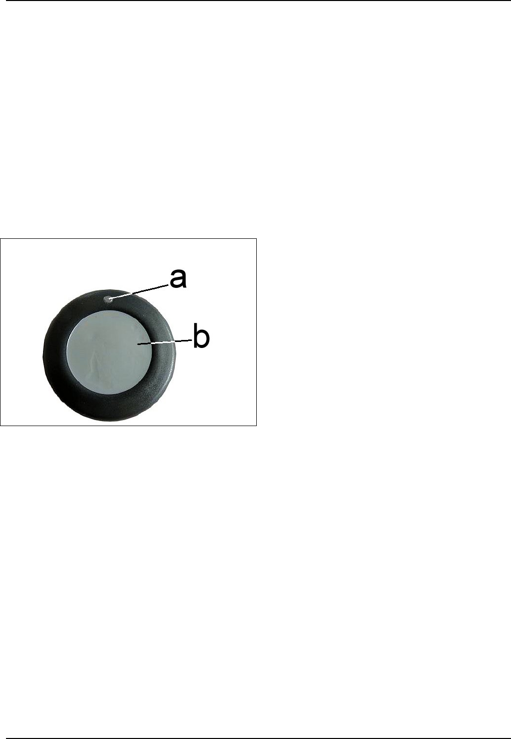
16
a LED – illuminates when the PTT button is
pressed
b PTT button
2.6.1 Subscription of the CT-Wireless-PTT to the PTT button
1. Switch OFF the radio unit connected to the PTT button if it is in switched-on state
2. Insert the CT-ClipCom ear microphones/earphones in the ears
3. Press the two keys (figure 14/e, f) of the PTT button
– Keep the keys depressed and switch the radio ON
– Continue keeping the two keys depressed until you hear a short beep in the RH CT-ClipCom
ear microphone/earphone
– After it, let the two keys go
4. Press the PTT key (figure 14/f) of the wire-bound PTT transmit button 3 times
– After it you hear the following tone sequence – beep-beep-beep….beep-beep-beep…beep-
5. Now press the PTT key on the CT-Wireless-PTT until you hear a long tone lasting 4 seconds.
Then let the key go. Now you hear again the previous sequence of beeps.
6. Now, press the PTT key of the PTT button once. After it, you hear no more beeps.
7. Then switch the communication system OFF.
Î PLEASE NOTE
As long as the PTT button is in programming mode, all other functions are disabled. To exit the
programming mode and enter into operating mode, the radio device must be switched OFF for at least
2 seconds and then switched ON again.
In case of loss of a CT-Wireless-PTT, we recommend deleting it from the receiver.

13
2.6.2 Deleting one CT-Wireless-PTT from the memory of a PTT button
1. Switch OFF the radio unit connected to the PTT button if it is in switched-on state
2. Insert the CT-ClipCom ear microphones/earphones in the ears
3. Press the two keys (figure 14/e, f) of the PTT button
– Keep the keys depressed and switch the radio ON
– Continue keeping the two keys depressed until you hear a short beep in the RH CT-ClipCom
ear microphone/earphone
– After it, let the two keys go
4. Press the PTT key (figure 14/f) of the wire-bound PTT transmit button once and keep it depressed
for at least 2 seconds. The deletion mode is now activated.
– In deletion mode your hear a very fast tone sequence
The deletion mode can be aborted by briefly pressing again the PTT key.
5. Now, press the PTT key for the CT-Wireless-PTT you want to delete and keep it depressed until
you hear a long tone lasting 4 seconds. The transmitter code is now deleted and you may release
the key.
2.6.3 Deleting all CT-Wireless-PTTs from the memory of PTT button
1. Switch OFF the radio unit connected to the PTT button if it is in switched-on state
2. Insert the CT-ClipCom ear microphones/earphones into the ears
3. Press the two keys (figure 14/e, f) of the PTT button
– Keep the keys depressed and switch the radio ON
– Continue keeping the two keys depressed until you hear a short beep in the RH CT-ClipCom ear
microphone/earphone
– After it, let the two keys go
4. Press the PTT key (figure 14/f) of the PTT button once and keep it depressed for at least 2
seconds. The deletion mode is now activated.
– In deletion mode your hear a very fast tone sequence.
The deletion mode can be aborted by briefly pressing again the PTT key.
5. Press now once more the PTT key of the wire-bound PTT transmit button for more than 2 seconds.
As soon as you hear a long tone lasting 4 seconds, all transmitter codes are deleted.
14
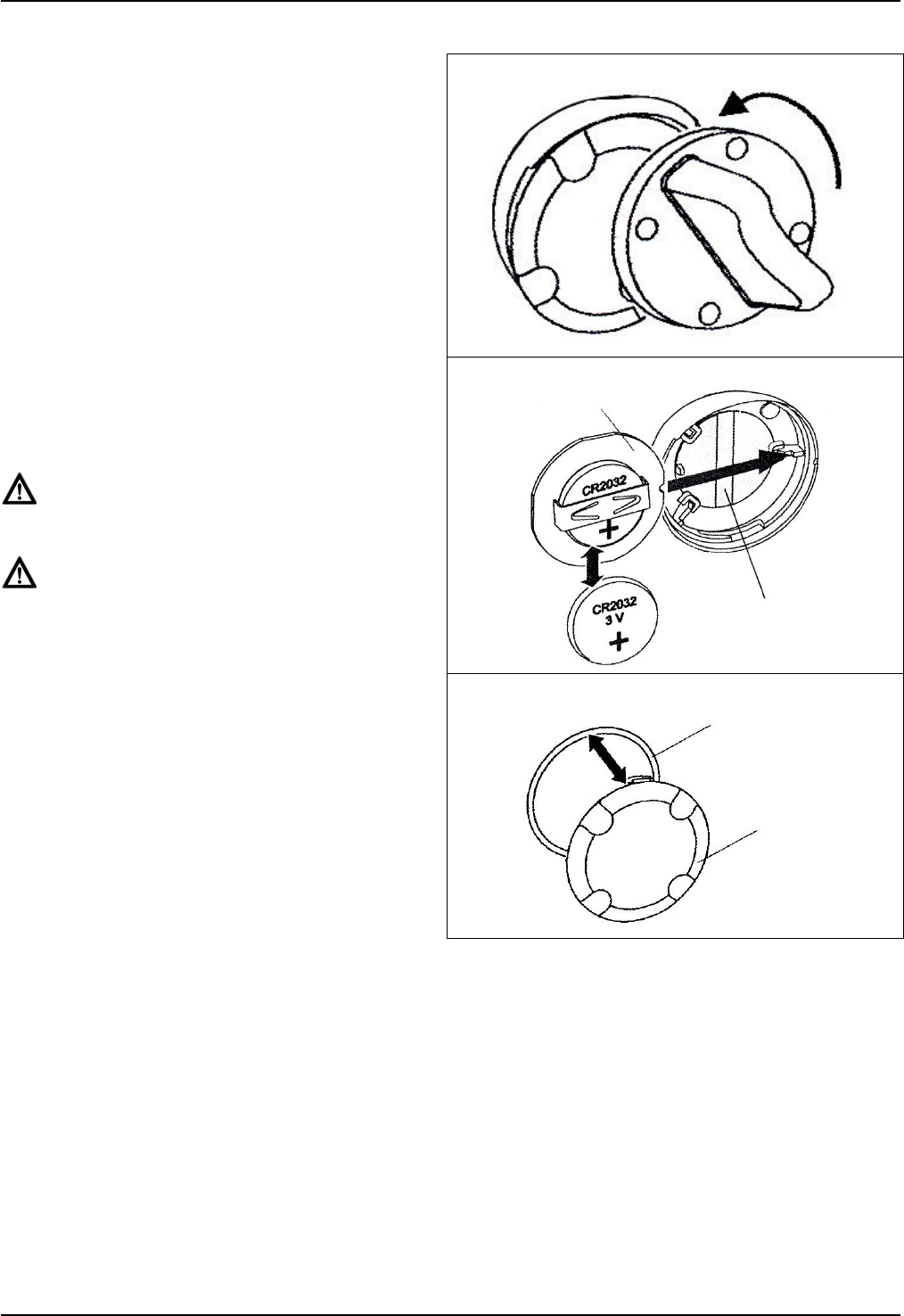
2.6.4 Changing the battery of the CT-Wireless-PTT
1. Open the battery compartment on the back of
the CT-Wireless-PTT using the opening tool
by a swift left turn.
17
2. Cautiously remove the circuit board from the
housing. Change the battery minding correct
polarity; lettering must be visible. Use 3-V
batteries type CR2032 only
ATTENTION
Mind correct polarity!
ATTENTION
Batteries may not be disposed off in the
domestic waste!
18
3. When closing the CT-Wireless-PTT put a new
sealing ring under the lid, if necessary.
Place the lid notches into the guides in the
housing and lock the lid with a right turn.
Make sure lid and housing have a tight fit.
19
3. Commissioning and operation
a. Connect the ear microphones/earphones to the PTT button (see figure 2 or 3).
b. Place the neck band with the PTT button around your neck. Adjust the size of the neck band.
c. Inserting the ear microphone/earphone: Place the ear hanger of the ear microphones /earphones
behind the ear. Insert the ear microphone / earphone into your ear. Adjust the seat of the ear
hanger, if necessary.
Please note for the use of individually ear moulds (not in scope of delivery): Insert the ear mould
into your ear with a quarter turn towards the back of the head until it has a snug fit.
circuit board
touch-lamina
sealing ring
lid

15
Caution
Wear the hearing protection in areas with noise without interruption.
Wear the hearing protection only like is described in this operation instructions.
Check the device periodically for signs of fractures, cracks and wear.
During disregard the protective effect of the hearing protection can be seriously impaired.
This hearing protection should not be carried if the danger exists that the cord gets caught or
drag along during carrying.
By a mechanical hit against the ear hanger can result harmful noise level.
d. Connect the PTT button via the plug and the radio adaptor to the radio. Switch the radio on and
adjust at the radio the desired volume of reception for the ear microphone.
CAUTION!
Before each start of operation control the volume of reception and adjust it, if necessary. Very
loud signals could damage your hearing.
Observe the manufacturer’s operating instruction for the radio device.
e. Transmitting and receiving: For transmitting (speaking) press the PTT button or the CT-Wireless-PTT
and keep it depressed. For safety reasons, keying of the CT-Wireless-PTT is limited to 30 seconds.
The radio is switched to transmission. You can speak as long as you keep the transmit button
depressed. Let the transmit button go in order to switch the radio back to standby/receiving (hearing).
CT-ClipCom Digital ear microphone
The DNR electronics (Digital Noise Reduction) filter and eliminate ambient noise from the voice
signal.
Radio messages are heard on both sides. In case a PTT transmit button is actuated the ear
microphone in the right ear switches from earphone to microphone operation. Consequently, the
ambient sound reception (ASR) of this ear microphone is not active.
CT-ClipCom Digital gooseneck microphone
The noise cancelling gooseneck microphone works without DNR function.
During activation of the PTT button, ambient sound reception is active on both sides.
4. Safekeeping – storage
After use, keep the cleaned devices in a clean and dry place at normal room temperature and at normal
relative air humidity.
5. Maintenance
5.1 Visual inspections
Check the CT-ClipCom Digital and particularly the cables and connectors periodically for signs of
fractures, cracks and wear. Check ear moulds and earphones/ear microphones after every use for
pollution.
Pollution can be the cause for skin irritation and malfunction.
5.2 Cleaning
ATTENTION!
When cleaning, make sure that no moisture penetrates inside the device. Do not use any
solvents (e.g. benzine, alcohol, sterilizing agents, etc.). After cleaning, keep earphones/ear
microphones unpacked until completely dry.
Obstructed sound channels of ear moulds and ear plugs cause poor communication in transmitting
(speaking) and reception (hearing). For periodical cleaning of components we recommend special
cleaning tissues (see chapter 6).
Clean the contacts of connectors with a commonly available contact cleaning agent.
Ear moulds and Earphones
Obstructed sound channels of ear moulds and earphones cause poor reception. For regular cleaning
(after every use) we recommend the use of special antiseptic cleaning tissues (see item 7), an
appropriate cleaning spray, or soft clean cloths and pure water with some dishwashing liquid.
Do not use solvents for cleaning purposes.
For a basic cleaning of ear moulds we recommend a cleaning bath once a week (effervescent tablets;
e.g. Detax Smarttabs) or ultrasonic bath.
5.3 Changing the protective cover of the gooseneck microphone
Check the protective foam cover periodically for pollution, wear and deformation and replace it, if
necessary. It can be easily pulled off the microphone.
6. Consumable parts + accessory
Designation Unit Part No.
Cleaning tissues pack of 100 6098293
Protective microphone cover pack of 10 50 022 03
Lithium button cell CR 2032 9801781
Set for changing battery with battery 9800906
Germany and
International Sales
CeoTronics AG
Adam-Opel-Str. 6
63322 Rödermark
Tel. +49 6074 8751-0
Fax +49 6074 8751-676
E-Mail sales@ceotronics.com
USA/Canada/Mexico
CeoTronics, Inc.
300 Southport Circle, Suite 103
Virginia Beach, Virginia 23452
Tel. +1 757 549-6220
Fax +1 757 549-6240
E-Mail sales@ceotronicsusa.com
France
CeoTronics Sarl
Bât. Delta T
Z.A. du Tuboeuf
Allée des Pleus
77170 Brie Comte Robert
Tel. +33 1 60183300
Fax +33 1 60286060
E-Mail ventes@ceotronics.fr
Spain
CeoTronics S.L.
C/Ciudad de Frias 7 y 9
Nave 19
28021 Madrid
Tel. +34 91 4608250 51
Fax +34 91 4603193
E-Mail ventas@ceotronics.es
Switzerland
CeoTronics AG
Grundstr. 16
6343 Rotkreuz
Tel. +41 41 7905838
Fax +41 41 7905839
E-Mail info@ceotronics.ch
Poland
CeoTronics Sp. z o.o.
ul. Słonecza 15
91-491 Łódź (Polska)
Tel. +48 42 6553311
Fax +48 42 6552288
E-Mail biuro@ceotronics.pl
Germany and
International Sales
CT-Video GmbH
Gewerbegebiet Rothenschirmbach 9
06295 Lutherstadt Eisleben
Tel. +49 34776 6149-0
Fax +49 34776 6149-11
E-Mail ctv.info@ceotronics.com
Revision: 01/0710 y DOK 1368-be Änderungen vorbehalten
Copyright © 11/2009 CeoTronics AG, 63322 Rödermark, Deutschland, Internet www.ceotronics.com