CeoTronics CT-TXRT27 Necklace Transmitter User Manual Ohrmikrofon CT HN
CeoTronics AG Necklace Transmitter Ohrmikrofon CT HN
UserManual.wiki
>
CeoTronics
>
CT TXRT27 User Manual
user manual
Navigation menu
Upload a User Manual
Namespaces
Wiki Guide
HTML
PDF
Info
Views
User Manual
Discussion / Help
Navigation
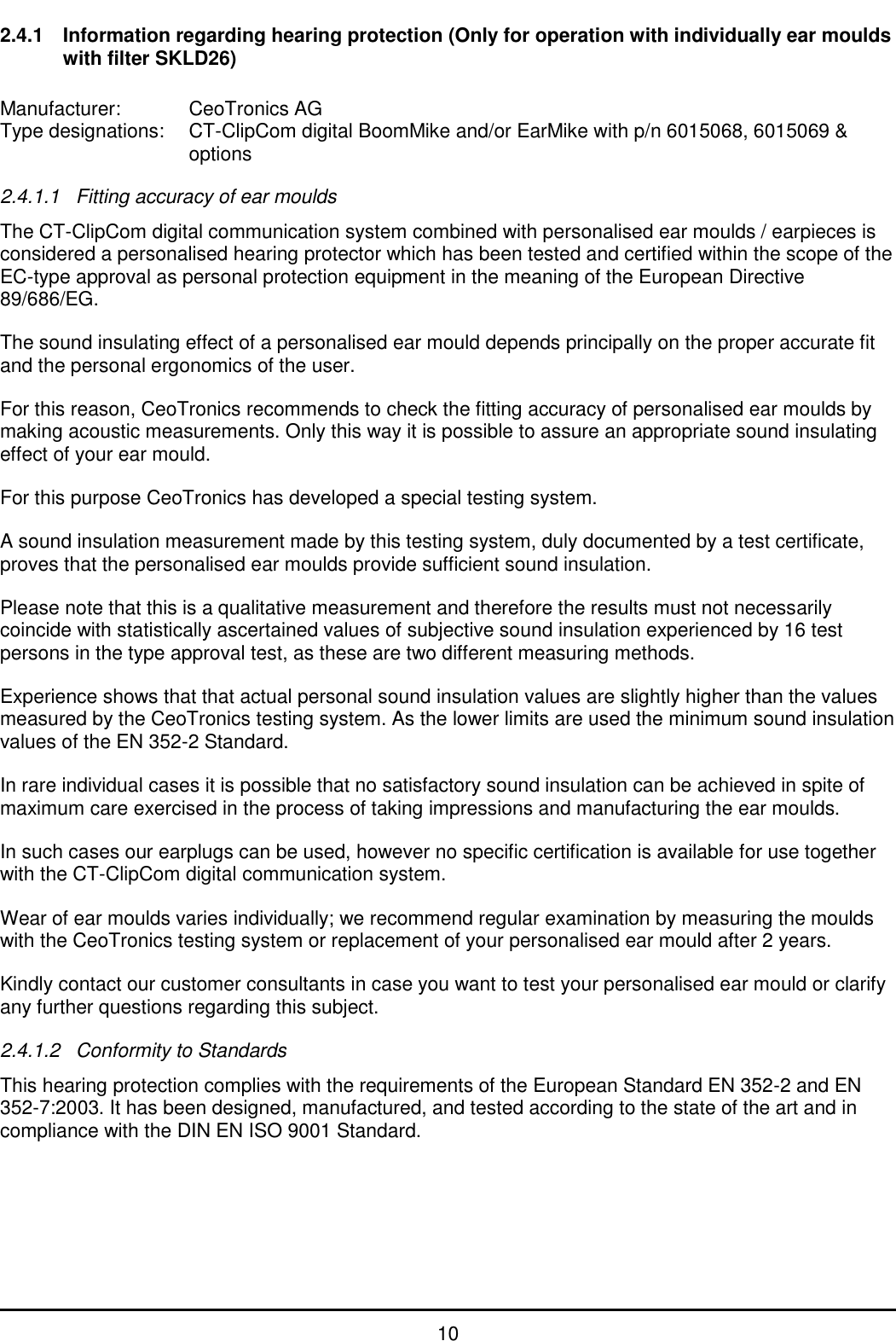
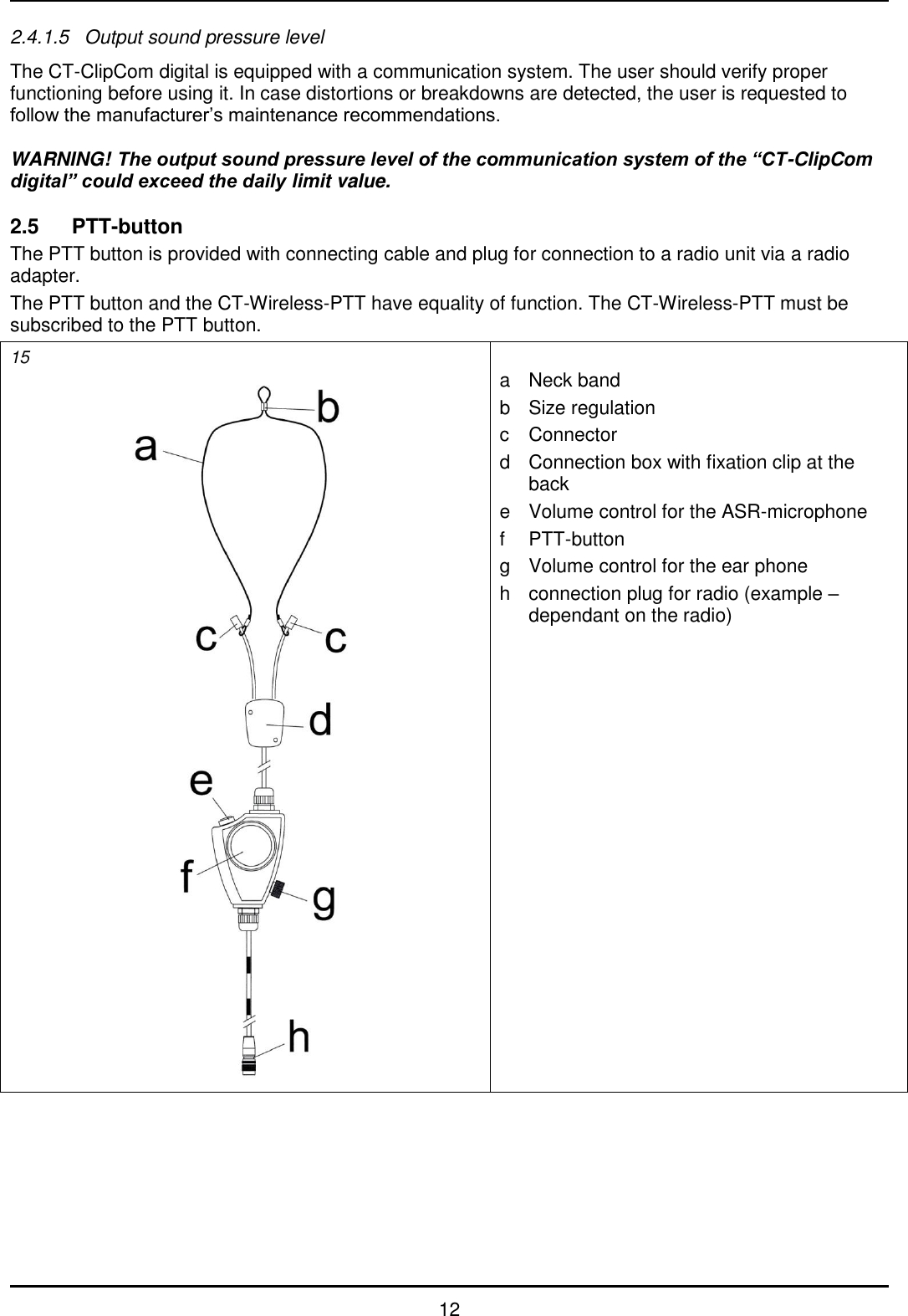
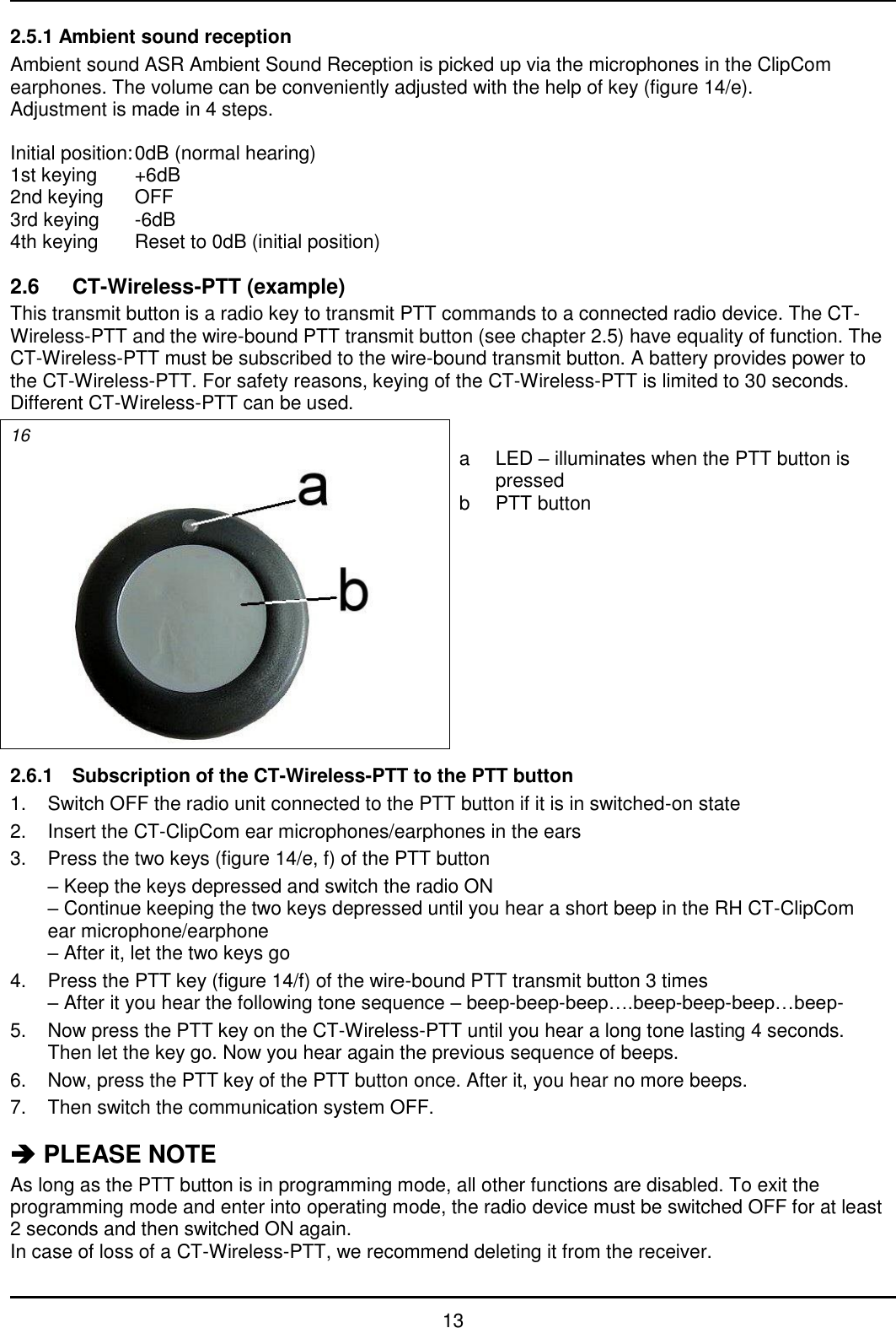
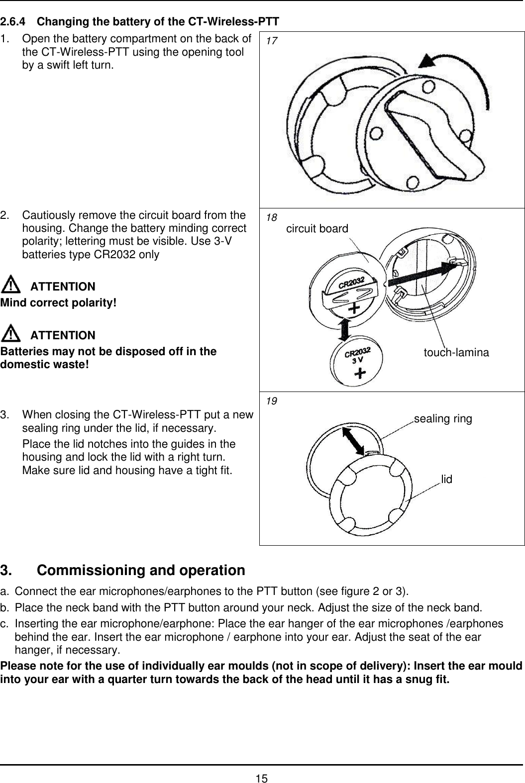
![11 Marking: 14 Example 2.4.1.3 General technical data Mass BoomMike: 17g EarMike: 6g 2.4.1.4 Sound insulation values with personalised ear moulds and SKLD26 filter Please take note that the certified ear moulds / earpieces and earplugs are able to function as hearing protection only if they are worn on both sides and both are covered by a CT-ClipCom system. For the one-sided version the sound insulation values of the table below may be used, provided that the other ear is covered with a sufficient sound insulation. Sound insulation of the personalised ear moulds and SKLD26 filter H = 27 dB M = 22 dB L = 21 dB SNR = 26 dB Result Frequency [Hz] Sound insulation [dB] Standard deviation [dB] APV [dB] 63 26,0 6,5 19,5 125 28,0 8,7 19,3 250 26,2 5,8 20,4 500 25,4 5,3 20,1 1000 25,6 4,7 20,9 2000 32,5 5,1 27,4 4000 35,6 3,5 32,1 8000 32,4 6,0 26,4 Level dependence with personalised ear moulds and SKLD26 filter Criterion level BoomMike EarMike H = 102,3 dB M = 102 dB L = 109,6 dB H = 98,8 dB M = 99 dB L = 111,8 dB The APV, H, M, L, and SNR values have been established according to EN ISO 4869-2 with parameter =1.](https://usermanual.wiki/CeoTronics/CT-TXRT27/User-Guide-1355759-Page-11.png)