Ceridian Canada DFTOUCHWR Time & Attendance Device User Manual R5
Ceridian Canada Ltd Time & Attendance Device Users Manual R5
Users Manual R5
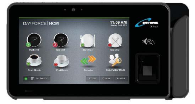
Ceridian’s
Dayforce Touch Clock
User Manual [ENG]
WARNING: This manual contains information on limitations regarding product use,
function and information on the limitation and liability of the manufacturer. Read the
entire manual carefully.

DF Touch
Page 2 of 23
Read and save these instructions! Follow all warnings and instructions
specified within this document and/or on the equipment. Always
ensure you obtain the latest version of the User Guide. Updated
versions of this User Guide are available by contacting your Ceridian
HCM administrator.
1 IMPORTANT SAFETY INSTRUCTIONS
To reduce the risk of fire, electric shock and/or injury, observe the
following safety precautions:
Do not spill any type of liquid on the equipment.
Do not attempt to service this product yourself. Opening or
removing the cover may expose you to dangerous voltage or
other risk. Refer servicing to qualified service personnel. Never
open the device yourself.
Do not touch the equipment and its connected cables during an
electrical storm; there may be a risk of electric shock.
2 REGULAR MAINTENANCE AND TROUBLESHOOTING
Keep your DF Touch Clock in optimal condition by following all the
instructions that are included within this manual and/or marked on the
product.
3 HANDLING PRECAUTIONS
Do not subject the touchscreen to mechanical shock (e.g.,
dropping or striking). Mechanical shock could damage the glass
display.
If the touchscreen glass is damaged, the liquid crystal fluid
inside could leak out. Avoid contact with the liquid crystal fluid.

DF Touch
Page 3 of 23
If the liquid crystal fluid comes into contact with your skin or
clothes, promptly wash it off using soap and water.
Do not apply excessive force to the display surface or adjoining
areas. Excessive force will distort the image on the display.
Do not use hard or sharp implements to operate the
touchscreen. Operating the touch screen with implements
harder than a finger could scratch the display.
Do not attempt to disassemble the LCD Module.
4 CLEANING
If the display surface is contaminated, moisten a use a soft cloth and
isopropyl alcohol to clean it. Other cleaners such as ketone (e.g.,
acetone), and/or aromatic solvents (e.g., benzene und toluene) may
damage the display. Do not use abrasives, thinners, solvents or aerosol
cleaners (i.e., spray polish). Any aromatic solvents, keytones etc. that
may enter through holes in the touch panel will cause damage.
Keep the ventilation slots clear of obstructions, dust buildup and liquids.
Do not spray liquids directly into the unit; avoid liquids entering into the
unit.
WARNING: This equipment shall be installed and used within an
environment that provides the pollution degree max 2 and over-
voltages category II non-hazardous locations, indoor only. It is designed
to be installed, serviced and/or repaired by service persons only [service
person is defined as a person having the appropriate technical training
and experience necessary to be aware of the hazards to which a person
may be exposed in performing a task and of measures to minimize the
risks to other persons]. With the exception of the battery, the end user
cannot replace any of the parts within the unit. These safety
instructions should not prevent you from contacting the installer or

DF Touch
Page 4 of 23
Dayforce HCM administrator to obtain any further clarification and/or
answers to your concerns.
DF Touch
Page 5 of 23
5 MAINTENANCE
With normal use, the system requires minimal maintenance. We
recommend, however, that the standby batteries be replaced every 3-5
years.
6 SPECIFICATIONS
This document describes the technical specifications of the DF Touch
clock terminal.
6.1 Display and Keypad
Capacitive Touch, 7 inch, 800x480 pixels, hardened glass surface.
6.2 Processor
CPU: 1GHz Dual Core ARM Cortex A9
RAM: Memory 1GByte 528 MHz SoDIMM, Non-volatile FLASH
memory 8GByte
6.3 Environment
Operating temperature: 0° to 40°C (32° to 104°F)
Storage temperature: -30° to 80°C (-22° to 176°F)
Humidity: 10% to 90% relative humidity, non condensing.
6.4 Power Supply
Input Power Jack:
24 VDC ±5%, 0.75 A, 20 W maximum
2.5mm barrel connector, center positive.
Power over Ethernet (PoE)
DF Touch
Page 6 of 23
IEEE 802.3at Type2, absolute operating input voltage 42.5-57VDC,
nominal draw 10Watts, max 20Watts.
Optional: External power supply
Input voltage 110-250 VAC, 0.5 A, 50/60Hz
Optional: Battery backup with Charger
Discharge life: 1.5 hours at 23°C (73°F)
Charge time: 16Hrs (on first use)
Charging (normal): 0° to 45°C (32° to 113°F)
Storage: -20° to 35°C (-4° to 95°F)
Discharging (battery: -20° to 60°C (-4° to 140°F)
6.5 Operating System
Android 4.0.3 (ICS)
6.6 Application Programs
Dayforce Clock Program
Dayforce Self Service
6.7 Enclosure
Plastic ABS/PVC Composite
6.8 Wall-mount Options
10 Degree hinged plastic ABS/PVC
10 Degree metal
40 Degree metal (extra cost – good for camera use)
6.9 Internet Connectivity
IEEE 802.3 10/100BASE-T/1000BASE-T Ethernet using TCP/IP
communication protocol and CAT-5 cable, cable lengths between
DF Touch
Page 7 of 23
the terminal and an Ethernet network hub can be up to 328 wire-
feet.
DHCP (Dynamic Host Configuration Protocol) is implemented to
assign IP addresses for the terminal, host and router. Static IP
addresses may also be assigned manually via the touch screen.
The terminal supports the use of DNS servers to convert host
names to host IP addresses in both DHCP and static IP modes.
Optional Wi-Fi 802.11 b/g/n
6.10 Camera
Integrated camera with 3 Megapixels resolution and torch flash.
6.11 LED
Three-color LED (red, green, blue) for status display
6.12 External USB ports
Two USB ports
For service use only
6.13 Optional readers & Modules (extra cost)
Fingerprint Biometric reader
Barcode slot reader (visible or infra-red light)
Magnetic slot reader
Proximity reader (125Khz or 13.5Mhz – for HID Proxpoint™,
iClass™, Mifare™, NFC)
6.14 Terminal Block
For Service Use Only
DF Touch
Page 8 of 23
6.15 Certifications
CE Mark, FCC Part 15 Class A
6.16 Time Synchronization
Terminal uses web service to synchronize its time with Dayforce
servers.
6.17 Dimensions (Approximate)
11 in (28cm) wide
5.5 in (14cm) high
2.25 in (6cm) deep without wall-mount
3 in (7.5cm) deep with 10 degree wall-mount
Weight about 4.4 lbs (2Kg) with packaging
DF Touch
Page 9 of 23
7 BATTERY PACK INSTALLATION INSTRUCTIONS
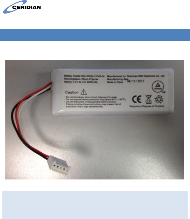
The battery pack resembles the figure below:
Figure 1: Battery Pack
Disclaimer: These instructions are for battery pack model SD-HK040-12145-14
manufactured by Shenzen DBK Electronics Co. Ltd. Use of any other battery is
not covered by this document is potentially hazardous and will void the
Dayforce Touch Clock warranty.
CAUTION! THERE IS A RISK OF EXPLOSION IF THE BATTERY IS REPLACED
BY WITH THE INCORRECT TYPE. DISPOSE OF USED BATTERIES
ACCORDING TO THE INSTRUCTIONS.
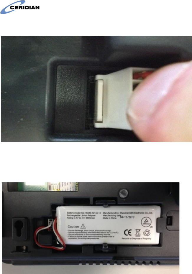
Place the battery socket lightly over the battery plug as pictured in the
figure below. Gently tilt the connector slightly to the left while pushing
down with your finger. The socket will clear the plastic housing and slide
down.
DF Touch
Page 10 of 23
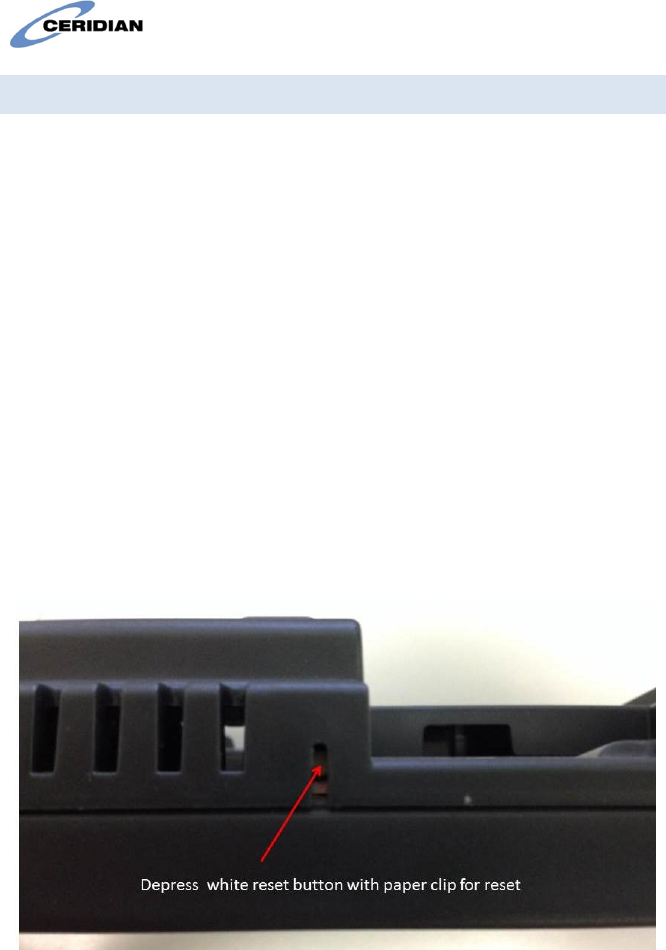
Final connector insertion
Insert the battery into the compartment and the cable into the guides
as pictured below:
Final battery pack insertion
DF Touch
Page 11 of 23
7.1 Charge the Battery
Power the unit from the AC/DC wall adapter or PoE. Batteries are
shipped uncharged. An uncharged battery must be charged for a period
of 66 hours before it will become fully charged and available for backup
power use.
Notes:
1. A system running on battery power can be shut down by pressing
the reset button which is located along the bottom edge of the
unit. This button can be pressed using a paper clip or small
screwdriver.
2. If operation on battery power is attempted before the battery
reaches full charge, there may be insufficient voltage to transition
to battery powered operation and the system will stop operating.
Place the system back on AC/DC wall adapter or PoE power. Press
the reset button if necessary to shut it down.
Reset switch location

DF Touch
Page 12 of 23
8 CAMERA USE APPLICATION NOTES
The following best practices are recommended for recording punches
using camera validation:
The punchers face should be well lit and be between 18 and 30
inches from the camera lens (which is on the top center of the
screen).
There should not be any other faces in the view of the camera
because the software will then not be able to decide which face
to capture.
There should not be a lot of movement behind the puncher.
For this reason, the clock should not be mounted in busy areas
if the camera function is to be used.
There should not be a light source in the camera’s view.
There are two camera validation options:
Face detection and capture: The clock captures an image of the
user’s face saves it in the clients instance so that it can then
optionally be viewed on the timesheet. This option uses a great
deal of data storage.
Facial recognition: Employees are enrolled for verification (i.e.,
their image is taken, saved, and distributed to clocks). When
employees punch, the clock attempts to validate that the image
it sees corresponds to the saved image.
The estimated punch rate when using camera validation should be
between 1 and 6 per minute depending on the option selected.
DF Touch
Page 13 of 23
9 INSTALLATION INSTRUCTIONS
The DF Touch Clock has two parts: the clock and the wall-mount. The
Clock is shipped in a cardboard carton together with the wall-mount,
keys for the lock, a 5 ft Ethernet cable, and the external power supply.
If necessary, detach the clock from the wall-mount using the key
supplied. Insert the key into the lock at the bottom of the wall-mount
and turn clock-wise 90 degrees, then lift the clock up and away from the
wall-mount. To install the wall mount, you will need four #8 screws and
(if necessary) the appropriate wall plugs.
9.1 Installing the wall-mount
Install the clock in areas that are well lit and not exposed to very hot,
cold, damp or dusty conditions. Install the wall-mount exactly
horizontally.
Figure 1: Wall-mount from rear
DF Touch
Page 14 of 23
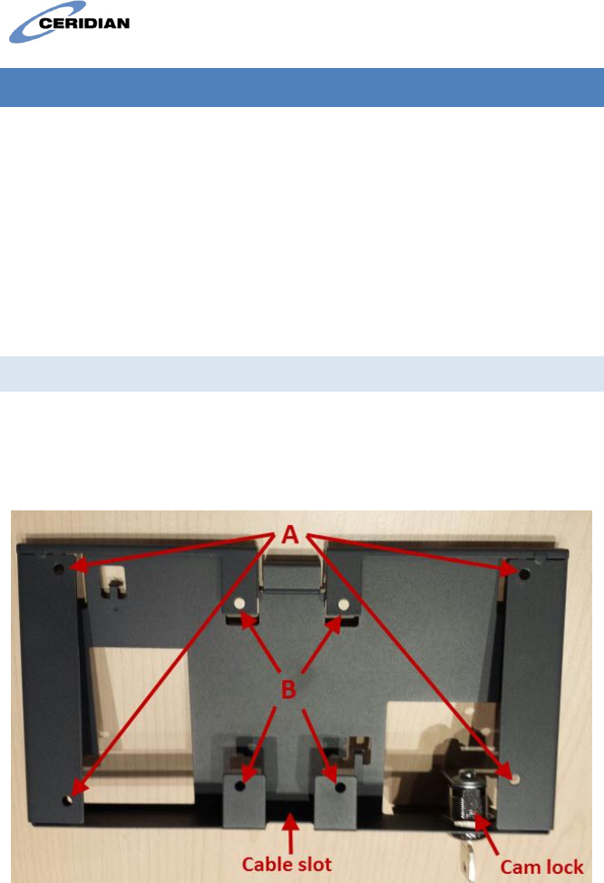
Use the holes marked A in Figure 1 to mount the clock to a wall, or the
holes marked B to attach the wall-mount to a standard NEMA double
gang electrical box.
The recommended height for mounting the clock differs depending on
your organization’s needs:
To accommodate users in wheelchairs, install the wall-mount
with its top edge 48 inches from the ground.
If the camera feature will be used, or if wheelchair access is not
required, install the wall mount with its top edge 56 inches from
the ground.
If the wall-mount is attached to an electrical box, insert the low-voltage
power cable and network cable through the wall. If the wall-mount is
attached to a wall, insert these cables through the cable slot.
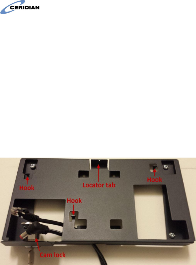
Figure 2 shows a wall-mount attached to the wall with the low-voltage
and network cables fed through the cable slot into the lock area. The
cam lock arm must be at 90 degrees to the wall.
Figure 2: Wall-mount with cables
DF Touch
Page 15 of 23
9.2 Connecting and attaching the clock
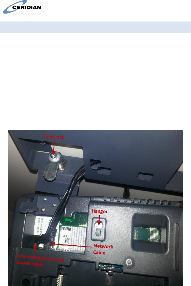
With the clock held close to the wall-mount, insert the cable plugs into
the appropriate receptacles. Figure 3 shows the clock with cables
connected.
With the cables connected, position the three hangers on the rear
housing over and above the hooks on the wall mount, using the tab at
the top of the clock as a guide. Then, push the clock down into the
hooks.
With the clock firmly on the hooks, rotate the key 90 degrees counter-
clockwise to secure the lock to the wall-mount. Finally, remove the key
from the lock.
Figure 3: Clock with cables connected
DF Touch
Page 16 of 23
9.3 Removing the clock
To remove the clock from the wall-mount, insert the key into the lock
and turn clockwise 90 degrees. You can then lift the clock off the hooks
and detach the cables.
9.4 Note re Power Supply
Clocks are supplied with both an external low current power pack which
delivers 24V DC and Power over Ethernet (PoE) functionality. The
external power pack need not be connected when PoE is available from
the Ethernet switch.
10 NETWORKING INFORMATION
The Ceridian DF Touch clocks have been designed to automatically
communicate with the Ceridian servers in the cloud when powered up
and connected to the internet.
All clocks must be assigned to a client in the Ceridian Admin Server by
Ceridian personnel before they will connect to a client’s instance.
Clients must provide the clocks with the ability to obtain its IP addresses
via DHCP. Alternatively, IP addressing can be manual by using the static
IP addressing function provided.
Clients, protected by a Firewall must allow the clocks to communicate
through ports UDP 123, TCP 443 and TCP 80.
Inter-clock communications uses port TCP 7750 within the local network
so this port should not be blocked within the local network.
The internet domain address used by the clocks is usually
dayforcehcm.com.
DF Touch
Page 17 of 23
10.1 Starting Up for the first time
The loader program will be loaded from memory.
10.2 Registration Pending Screen
The message “This time clock is not registered. Please contact your
system administrator for assistance” means that the clock is
communicating with the Ceridian Servers but has not been assigned.
The message “To register the time clock connect it to your network and
press “Register Now”” means that the clock is not connected to the
internet.
Clocks with a Ceridian Clock Program Loaded show a round green dot
(the status indicator) in the lower left hand of the screen to indicate
that the clock is communicating successfully. An orange (yellow)
indicator means that there may be a communications problem.
11 TROUBLESHOOTING NETWORK CONNECTIVITY
Does the clock have an IP address?
Use Administrator Mode (Refer to the “Dayforce Touch Clock Guide”) to
view the IP address. If there is no IP address please check:
that the Ethernet cable is connected to a live port
that the DHCP server is functioning or if IP addresses are
manually set that all the IP information has been entered
appropriately.
11.1 Testing network access:
Try to ping the IP address of the clock. If there is no ping response try
resetting the clock (see reset instructions below).
DF Touch
Page 18 of 23
Check that your firewall is not blocking the clock (ports UDP 123, TCP
443 and TCP 80 must be unblocked).
Disconnect the clock from the Ethernet port and connect a computer to
the port then use a browser to access the following internet site:
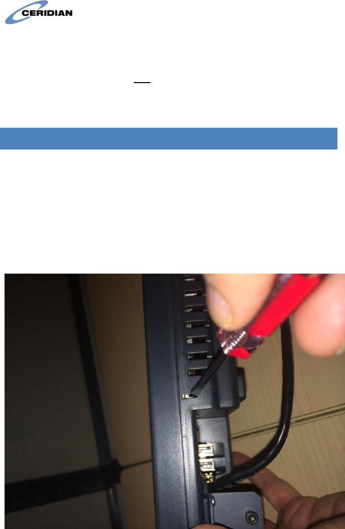
https://punch.dayforcehcm.com/deviceservices/DeviceServiceJSON.svc
You should see the following reply:
You don’t need to compare the entire message; as long as the page
starts with “Service”, and the first part of the message is similar, it
means you have connectivity to the Ceridian server.
If you get an obviously different message (e.g., “Cannot display the
webpage”), then there is an issue preventing access to the Ceridian
server.
1. If you get the “Service” page as described in the previous step,
but the clock is still not connecting (yellow status icon), then
please send the following information to the project team who
will forward it to Ceridian for further investigation:
DF Touch
Page 19 of 23
Screenshots of the browser when attempting to access
the links from step 1.
The clock IP and MAC addresses. For more information
about finding these addresses, refer to the Clock
Information section later in this manual.
12 RESETTING THE CLOCK:
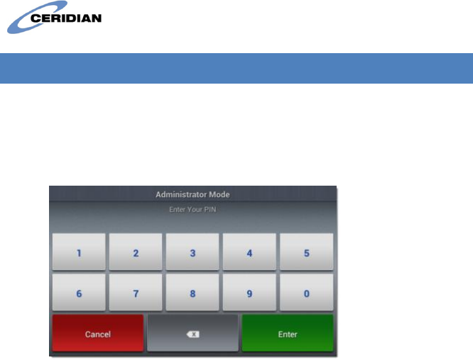
Reset the clock by pressing the reset button at the bottom of the clock.
Use a small flat head screwdriver as shown in the picture below (or the
end of a paper clip) to reach the button and press gently.
Alternatively, use the Reset control on the Administrator Mode Screen,
or (if there is no battery backup installed), temporarily remove external
power from clock.
DF Touch
Page 20 of 23
13 CLOCK INFORMATION AND SETUP STATIC IP:
1. On the home screen, touch and hold the Welcome to Dayforce
HCM message.
After a few seconds, the application prompts you to type the
admin mode PIN:
2. Type the administrator mode PIN.
Note: The default PIN is 4110, but may be changed without
notice by system administration.
3. Tap the Enter button.
The clock displays the Administrator Mode screen. To view the current
clock IP and MAC address, tap Clock Information
To set up Static IP:
1. Tap Network Setup and choose Ethernet Configuration.
2. Clear the Use Dynamic IP Address check box.
3. Type the following information into the appropriate fields:
o IPv4 Address
o Subnet Mask
o Default Gateway
o Primary DNS Server
o Secondary DNS server
4. Verify the IP address on the Clock Information screen.

DF Touch
Page 21 of 23
14 COMPLIANCE INFORMATION
This device complies with Part 15 of the FCC Rules. Operation is subject
to the following two conditions: (1) this device may not cause harmful
interference, and (2) this device must accept any interference received,
including interference that may cause undesired operation.
This device complies with Industry Canada license-exempt RSS
standard(s). Operation is subject to the following two conditions: (1)
this device may not cause interference, and (2) this device must accept
any interference, including interference that may cause undesired
operation of the device.
Changes or modifications not approved by the manufacturer could void
the user’s authority to operate the equipment.
This equipment complies with FCC radiation exposure limits set forth for
an uncontrolled environment. In order to avoid the possibility of
exceeding the FCC radio frequency exposure limits, human proximity to
the antenna shall not be less than 20cm during normal operation.
This equipment complies with IC RSS-102 radiation exposure limits set
forth for an uncontrolled environment. This equipment should be
installed and operated with minimum distance 20cm between the
radiator & your body.
Under Industry Canada regulations, this radio transmitter may only
operate using an antenna of a type and maximum (or lesser) gain
approved for the transmitter by Industry Canada. To reduce potential
radio interference to other users, the antenna type and its gain should
be so chosen that the equivalent isotropically radiated power (e.i.r.p.) is
not more than that necessary for successful communication.
Le présent appareil est conforme aux CNR d'Industrie Canada
applicables aux appareils radio exempts de licence. L'exploitation est
autorisée aux deux conditions suivantes : (1) l'appareil ne doit pas
produire de brouillage, et (2) l'utilisateur de l'appareil doit accepter tout
brouillage radioélectrique subi, même si le brouillage est susceptible
d'en compromettre le fonctionnement.

DF Touch
Page 22 of 23
Cet équipement est conforme aux limites d'exposition aux
rayonnements énoncées pour un environnement non contrôlé et
respecte les règles d'exposition aux fréquences radioélectriques (RF)
CNR-102 de l'IC. Cet équipement doit être installé et utilisé en gardant
une distance de 20 cm ou plus entre le dispositif rayonnant et le corps

DF Touch
Page 23 of 23
15 CONTACTS
USA: Ceridian HCM, Inc
3311 East Old Shakopee Road
Minneapolis 55425 MN.
For support call +1 866 748-7066
Canada: Ceridian Canada Ltd
125 Gary Street
Winnipeg, R3C 3P2
For support call +1 877 237-4342
Europe: Ceridian UK Limited
100 Longwater Avenue
Green Park, Reading
Berkshire RG2 6GP
For support call +44 844 893-1400