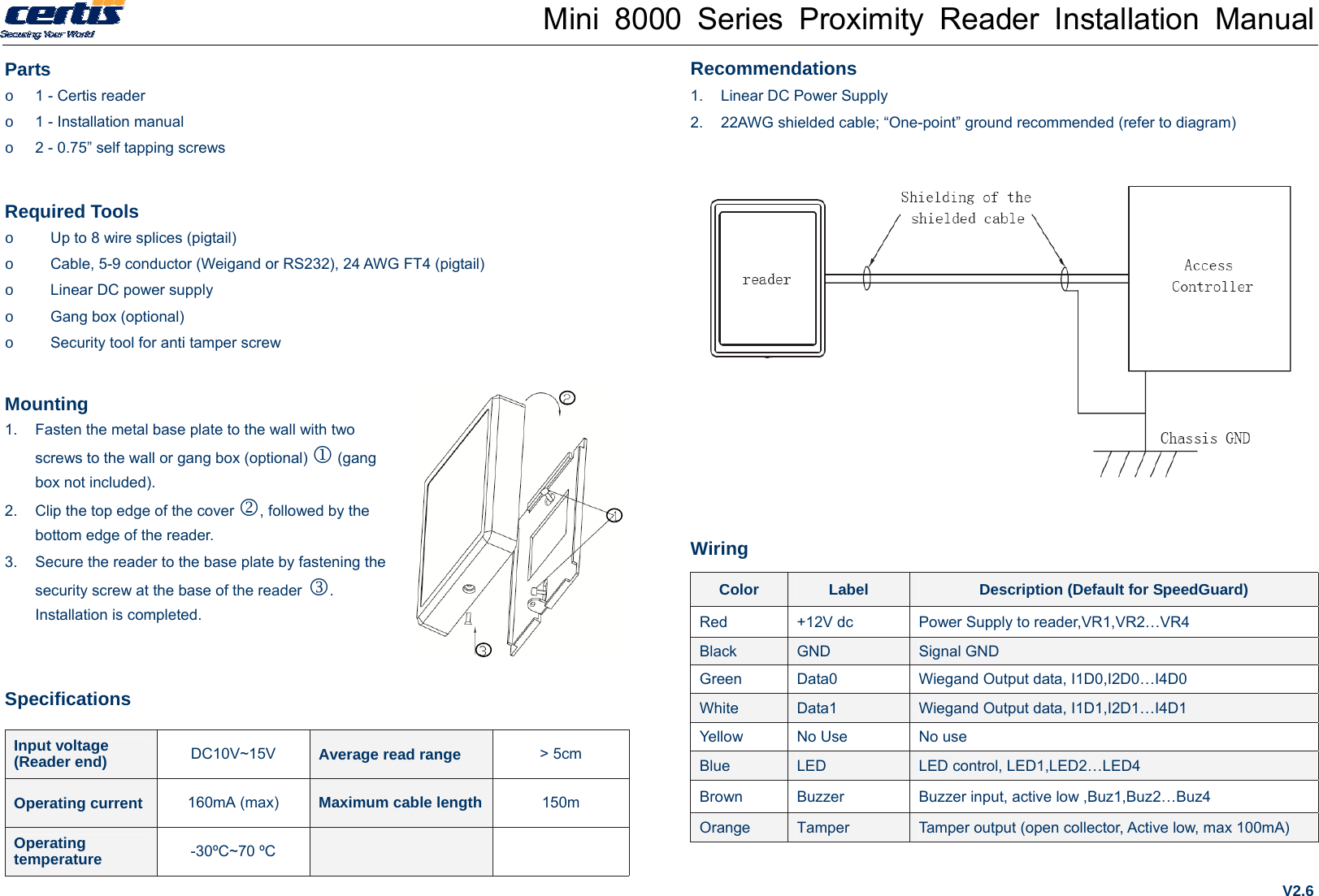
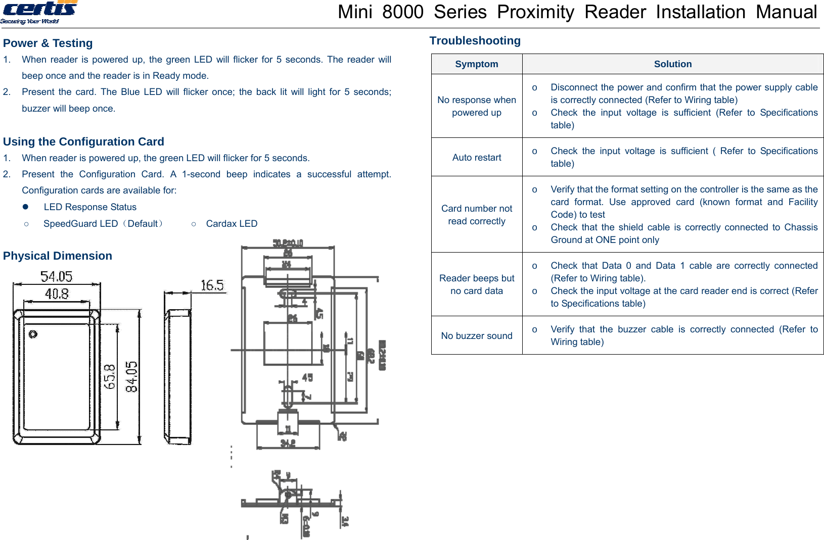
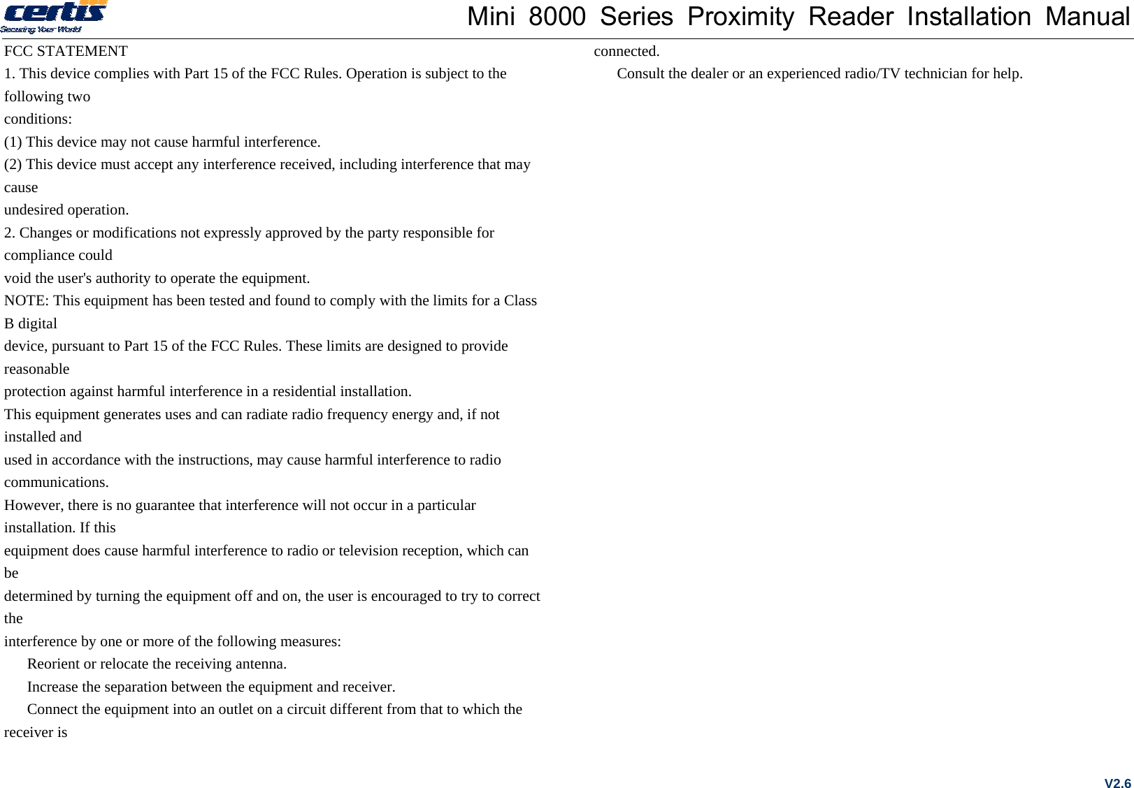
Certis Technology CEK9PROXRDR Access Control Reader User Manual

Certis Technology International Pte Ltd Access Control Reader Users Manual

Users Manual

Mini 8000 Series Proximity Reader Installation Manual Parts o  1 - Certis reader o  1 - Installation manual o  2 - 0.75” self tapping screws  Required Tools o  Up to 8 wire splices (pigtail) o  Cable, 5-9 conductor (Weigand or RS232), 24 AWG FT4 (pigtail) o  Linear DC power supply o  Gang box (optional) o  Security tool for anti tamper screw Mounting 1.  Fasten the metal base plate to the wall with two screws to the wall or gang box (optional)  (gang box not included). 2.  Clip the top edge of the cover , followed by the bottom edge of the reader.   3.  Secure the reader to the base plate by fastening the security screw at the base of the reader . Installation is completed. Specifications Input voltage   (Reader end)  DC10V~15V  Average read range  > 5cm Operating current  160mA (max)  Maximum cable length 150m Operating temperature  -30ºC~70 ºC    Recommendations 1.  Linear DC Power Supply 2.  22AWG shielded cable; “One-point” ground recommended (refer to diagram)           Wiring Color  Label  Description (Default for SpeedGuard) Red  +12V dc  Power Supply to reader,VR1,VR2…VR4 Black  GND  Signal GND Green  Data0  Wiegand Output data, I1D0,I2D0…I4D0 White  Data1  Wiegand Output data, I1D1,I2D1…I4D1 Yellow  No Use  No use Blue  LED  LED control, LED1,LED2…LED4 Brown  Buzzer  Buzzer input, active low ,Buz1,Buz2…Buz4 Orange  Tamper  Tamper output (open collector, Active low, max 100mA) V2.6
Mini 8000 Series Proximity Reader Installation Manual Power & Testing 1.  When reader is powered up, the green LED will flicker for 5 seconds. The reader will beep once and the reader is in Ready mode. 2.  Present the card. The Blue LED will flicker once; the back lit will light for 5 seconds; buzzer will beep once.    Using the Configuration Card 1.  When reader is powered up, the green LED will flicker for 5 seconds.   2.  Present the Configuration Card. A 1-second beep indicates a successful attempt. Configuration cards are available for:   LED Response Status ○   SpeedGuard LED(Default)     ○  Cardax LED  Physical Dimension       Troubleshooting  Symptom  Solution No response when powered up o  Disconnect the power and confirm that the power supply cable is correctly connected (Refer to Wiring table) o  Check the input voltage is sufficient (Refer to Specifications table) Auto restart  o  Check the input voltage is sufficient ( Refer to Specifications table) Card number not read correctly o  Verify that the format setting on the controller is the same as the card format. Use approved card (known format and Facility Code) to test o  Check that the shield cable is correctly connected to Chassis Ground at ONE point only Reader beeps but no card data o  Check that Data 0 and Data 1 cable are correctly connected (Refer to Wiring table). o  Check the input voltage at the card reader end is correct (Refer to Specifications table) No buzzer sound o  Verify that the buzzer cable is correctly connected (Refer to Wiring table) 
Mini 8000 Series Proximity Reader Installation Manual FCC STATEMENT 1. This device complies with Part 15 of the FCC Rules. Operation is subject to the following two conditions: (1) This device may not cause harmful interference. (2) This device must accept any interference received, including interference that may cause undesired operation. 2. Changes or modifications not expressly approved by the party responsible for compliance could void the user's authority to operate the equipment. NOTE: This equipment has been tested and found to comply with the limits for a Class B digital device, pursuant to Part 15 of the FCC Rules. These limits are designed to provide reasonable protection against harmful interference in a residential installation. This equipment generates uses and can radiate radio frequency energy and, if not installed and used in accordance with the instructions, may cause harmful interference to radio communications. However, there is no guarantee that interference will not occur in a particular installation. If this equipment does cause harmful interference to radio or television reception, which can be determined by turning the equipment off and on, the user is encouraged to try to correct the interference by one or more of the following measures:   Reorient or relocate the receiving antenna.   Increase the separation between the equipment and receiver.   Connect the equipment into an outlet on a circuit different from that to which the receiver is connected.   Consult the dealer or an experienced radio/TV technician for help. V2.6

Navigation menu