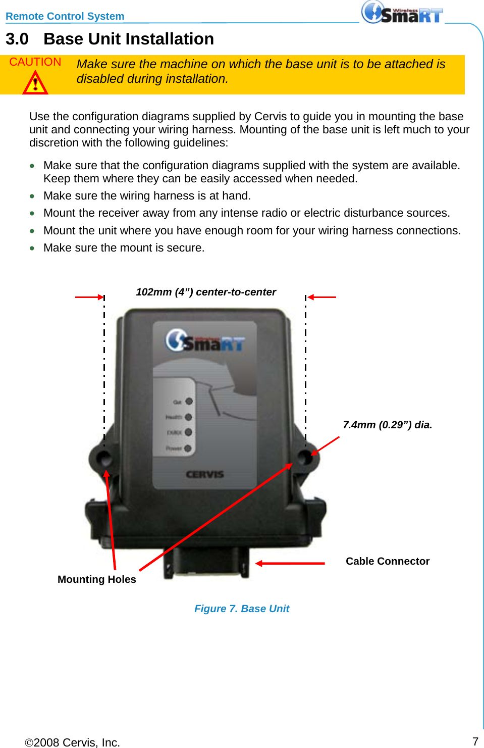
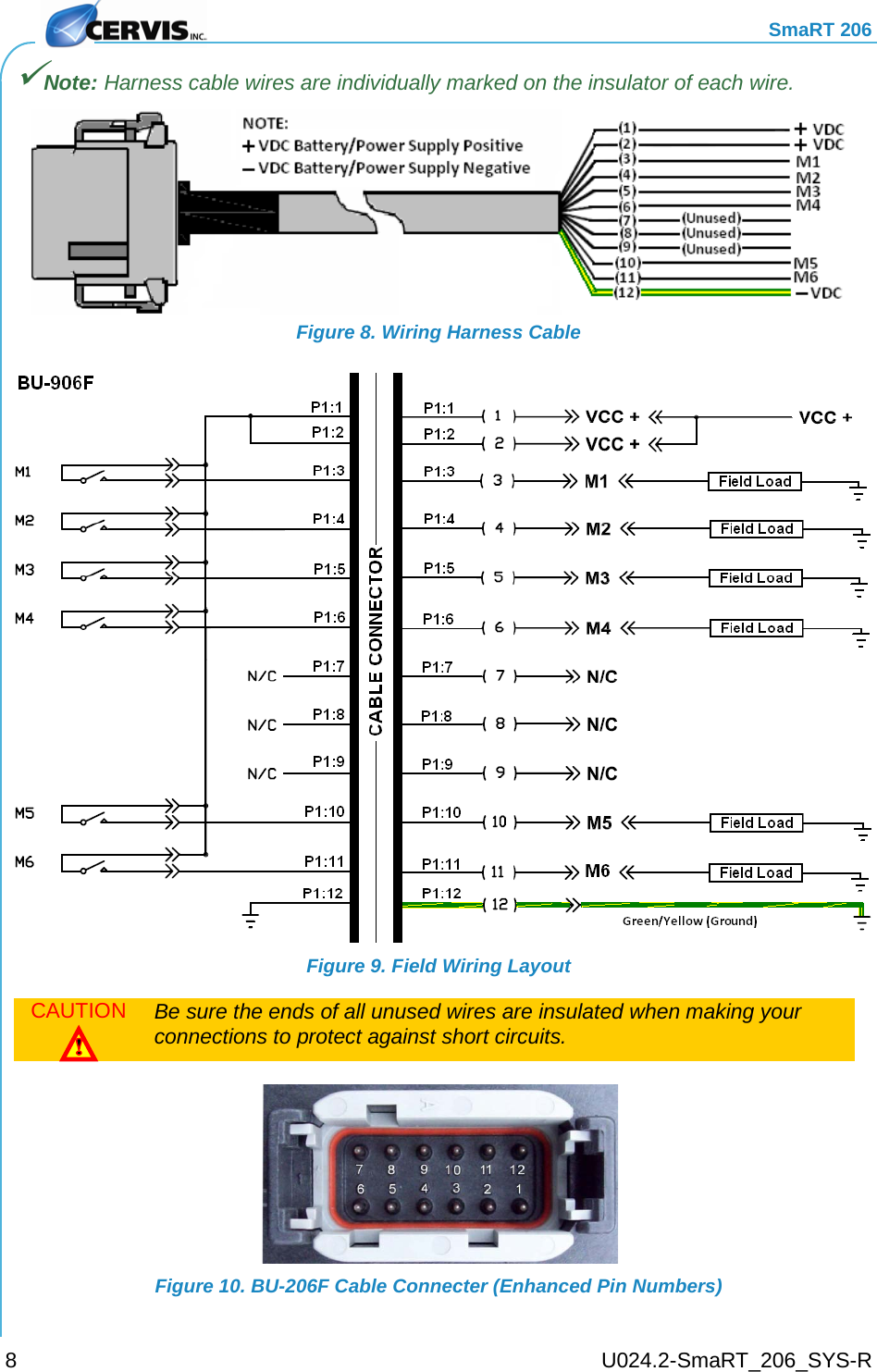
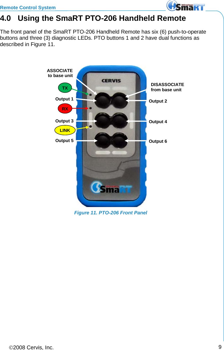
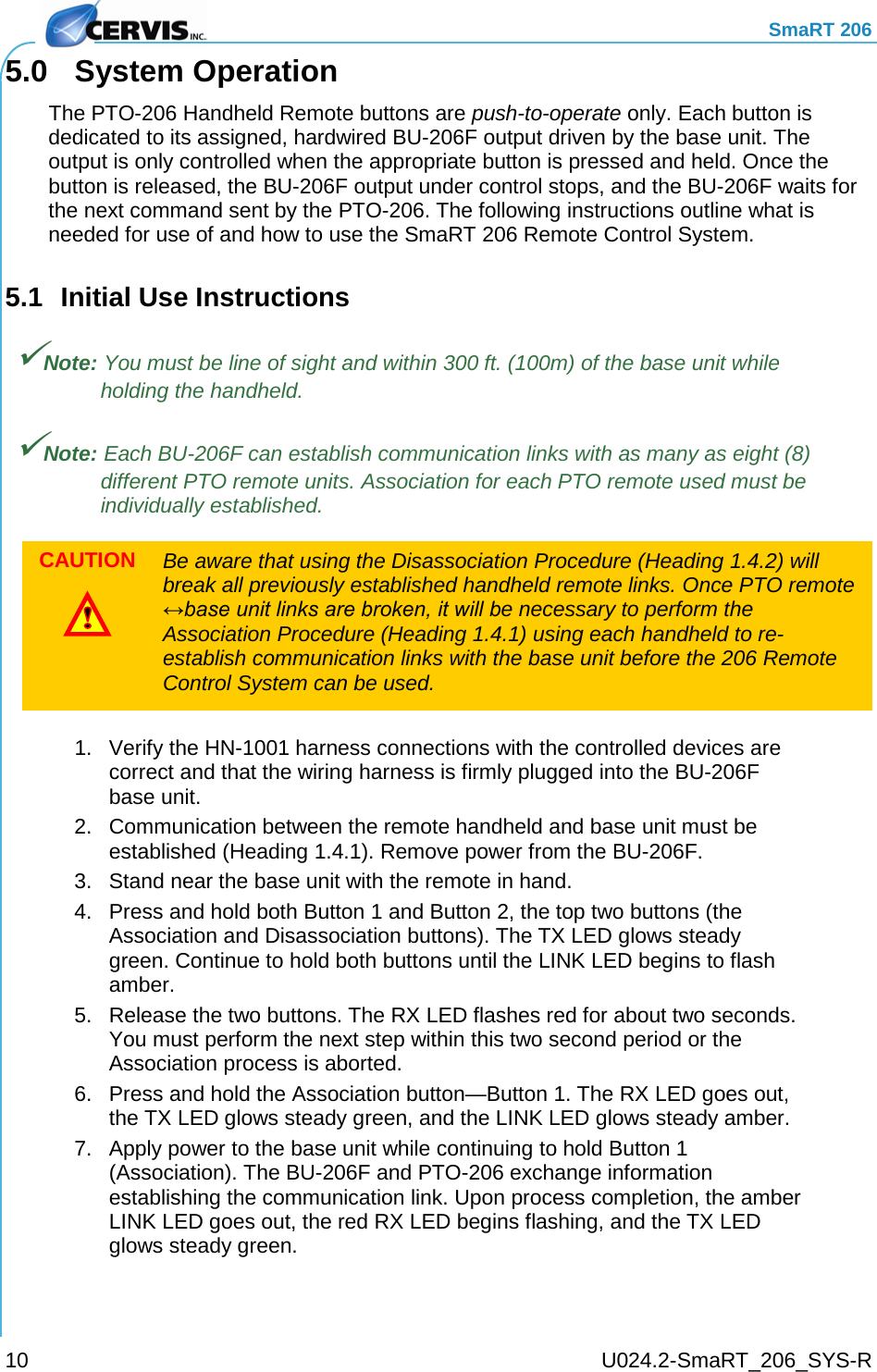
Cervis SHH200 Handheld Remote Controller User Manual SmaRT 206 Remote Control System

Cervis Inc. Handheld Remote Controller SmaRT 206 Remote Control System

user manual

 2008 Cervis, Inc.    206 Remote Control System User Manual DN: U024.2-SmaRT_206_SYS-R ™
    SmaRT 206   Cervis, Inc. Visit our Web site at:  www.cervisinc.com   2008 Cervis, Inc. All rights reserved. Content is subject to change without notice.     This document is the property of Cervis, Inc. and cannot be copied, modified, e-mailed, or reproduced without the express prior written consent of Cervis, Inc. Cervis, Inc. reserves the right to change this manual or edit, delete, or modify any information without prior notification.  FCC Statements 15.19 – Two Part Warning This device complies with Part 15 of the FCC rules. Operation is subject to the following two conditions: (1) This device may not cause harmful interference and  (2) This device must accept any interference received, including interference that may cause undesired operation. 15.21 – Unauthorized Modification NOTICE: The manufacturer is not responsible for any unauthorized modifications to this equipment made by the user. Such modifications could void the user’s authority to operate the equipment. 15.105(b) – Note:  This equipment has been tested and found to comply with the limits for a Class B digital device, pursuant to Part 15 of the FCC Rules. These limits are designed to provide reasonable protection against harmful interference in a residential installation. This equipment generates, uses and can radiate radio frequency energy and, if not installed and used in accordance with the instructions, may cause harmful interference to radio communications. However, there is no guarantee that interference will not occur in a particular installation. If this equipment does cause harmful interference to radio or television reception, which can be determined by turning the equipment off and on, the user is encouraged to try to correct the interference by one or more of the following measures: • Reorient or relocate the receiving antenna. • Increase the separation between the equipment and receiver. • Connect the equipment into an outlet on a circuit different from that to which the receiver is connected.  Industry Canada Statement (for use within Canada) This device complies with Canadian RSS-210. The installer of this radio equipment must ensure that the antenna is located or pointed such that it does not emit RF field in excess of Health Canada limits for the general population; consult Safety Code 6, obtainable from Health Canada’s website www.hc-sc.gc-ca/rpb.
Remote Control System 2008 Cervis, Inc.     i  Table of Contents Cervis Inc. Safety Precautions ................................................................................................... ii Definitions/Notes ......................................................................................................................... iii 1.0 SmaRT 206 Remote Control System .................................................................................. 1 1.1 Features ............................................................................................................................. 1 1.2 PTO-206 Handheld Remote .............................................................................................. 2 1.3 BU-206F Base Unit ............................................................................................................ 3 1.4 Handheld ↔ Base Unit Communication ........................................................................ 4 1.4.1 Handheld ↔ Base Unit Association ............................................................................ 4 1.4.2 Handheld ↔ Base Unit Disassociation ....................................................................... 5 2.0 Handheld Battery Installation or Change .......................................................................... 6 3.0 Base Unit Installation........................................................................................................... 7 4.0 Using the SmaRT PTO-206 Handheld Remote .................................................................. 9 5.0 System Operation .............................................................................................................. 10 5.1 Initial Use Instructions ................................................................................................... 10 6.0 Specifications ..................................................................................................................... 12 6.1 PTO-206 Handheld Remote ............................................................................................ 12 6.2 BU-206F Base Unit .......................................................................................................... 13  List of Figures Figure 1. PTO-206 Handheld Remote and BU-206F Base Unit .................................................. 1 Figure 2. PTO-206 ........................................................................................................................... 2 Figure 3. BU-206F Twelve (12) Pin Connector ............................................................................ 3 Figure 4. BU-206F LEDs ................................................................................................................ 3 Figure 5. Handheld PTO Front Panel ........................................................................................... 4 Figure 6. Handheld Battery Installation ....................................................................................... 6 Figure 7. Base Unit ......................................................................................................................... 7 Figure 8. Wiring Harness Cable .................................................................................................... 8 Figure 9. Field Wiring Layout ........................................................................................................ 8 Figure 10. BU-206F Cable Connecter (Enhanced Pin Numbers) ............................................... 8 Figure 11. PTO-206 Front Panel .................................................................................................... 9
    SmaRT 206     U024.2-SmaRT_206_SYS-R ii Cervis Inc. Safety Precautions  Read  and follow all instructions.   Failure to abide by Safety Precautions may result in equipment failure, loss of authority to operate the equipment, and personal injury.  Use and maintain proper wiring. Follow equipment manufacturer instructions. Improper, loose, and frayed wiring can cause system failure, equipment damage, and intermittent operation.  Changes or modifications made to equipment not expressly approved by the manufacturer will void the warranty.  Owner/operators of the equipment must abide by all applicable Federal, State, and Local laws concerning installation and operation of the equipment. Failure to comply could result in penalties and could void user authority to operate the equipment.  Make sure that the machinery and surrounding area is clear before operating. Do not activate the remote control system until certain that it is safe to do so.  Turn off the handheld remote and remove power from the base unit  before attempting any maintenance. This will prevent accidental operation of the controlled machinery.  Use a damp cloth to keep units clean. Remove mud, concrete, dirt, etc. after use to prevent obstructing or clogging the buttons, levers, wiring, and switches.  Do not allow liquid to enter the handheld or base unit enclosures. Do not use high pressure equipment to clean the handheld remote or base unit.  Disconnect the radio base unit before welding on the machine. Failure to disconnect the base unit may result in destruction of or damage to the base unit.  Operate and store units only within the specified operation and storage temperatures defined in 6.0 Specifications of this document.
Remote Control System 2008 Cervis, Inc.     iii Definitions/Notes Association SmaRT configuration method using a series of specific remote unit button presses to establish a communication link between a SmaRT Handheld and a SmaRT Base Unit. DSSS Direct sequence spread spectrum; an advance wireless communication technology. Disassociation Dissolution of all established communication links between handhelds and a base unit.  FET Field effect transistor: Type of transistor that relies on an electric field to control the conductivity of the device. IP65 IEC (International Electrotechnical Commission) rating that classifies the level of protection provided by an enclosure. IP (international protection) 6 (dust tight) 5 (water jetted from any direction on the enclosure shall have no harmful effects)  PTO Push to Operate: Command broadcast only while a button is depressed. The command ends when the button is released. BU-206F  Remote base unit with six outputs controlled by a SmaRT Handheld unit. Each SmaRT BU-206F can communicate with up to eight handhelds. SmaRT 20N Remote Control System SmaRT system consisting of one SmaRT Base Unit and from one to eight SmaRT remote control units. The system operates in the 2.4GHz range and has some defined number (N) of outputs. For instance, a SmaRT 206 Remote Control System operates in the 2.4GHz range, and a maximum of six outputs can be controlled by the remote. Line of Sight (aka Direct-Line-of-Sight) Type of communication between transceivers, or a transmitter and a receiver, where the pathway between the two units must be clear of obstacles. TX/RX Transmit/Receive
    SmaRT 206     U024.2-SmaRT_206_SYS-R iv This page is intentionally left blank.
  1.0  SmaRT 206 Remote Control System The standard SmaRT 206 Remote Control System consists of a 6-Button PTO-206 wireless handheld transmitter, a BU-206F base unit, and the wiring harness that is used to connect the base unit to the controlled apparatus. A single base unit is capable of communicating with up to eight PTO-206 Handheld units. The rugged construction, compact size, and multiple output versatility allow for SmaRT Systems to be used for many applications that require remote operation.  Figure 1. PTO-206 Handheld Remote and BU-206F Base Unit 1.1 Features • Rugged compact weatherproof high-impact polymer IP65 enclosures • Operating Temp: -20°C to +55°C • Storage Temp: -40°C to +85°C • License Free Frequency, 2.4GHz Direct Sequence Spread Spectrum Technology • 300 ft. (100m) Range • PTO-206 Handheld  • Remote has six Push-to-Operate (PTO) buttons  • Powered by three AAA Batteries (+3.6 to 4.5VDC) • Removable rubber bumper and lanyard • Three status/diagnostic LEDS • Base Unit  • +9 to +16VDC Input Power (optional +16 to +32VDC input available) • Six FET high-side switching outputs (24A max.) • Four status/diagnostic LEDs • Single connector interface for ease of wiring
    SmaRT 206     U024.2-SmaRT_206_SYS-R 2 1.2 PTO-206 Handheld Remote The SmaRT PTO-206 Handheld Remote features a handheld-to-base unit 300 ft. (100m) communication range providing six function press-to-operate (PTO) control. Using direct sequence spread spectrum (DSSS) wireless technology at 2.4GHz, the handheld unit provides a robust link with a base unit in congested radio environments. SmaRT handheld units feature seamless association to a SmaRT BU-206F Base Unit without the need to open either case. The handheld enclosure is constructed of rugged high-impact polymer and a polycarbonate face plate securely sealed and attached by eight screws that is then overlaid with a durable, attractively printed polycarbonate label. The unit is further protected by a removable rubber bumper that extends beyond the recessed faceplate and covers the back and sides. A convenient removable lanyard is provided that can be securely attached to the bottom of the remote. The handheld is powered by three size AAA batteries. Three status/diagnostic LEDs are visible on the handheld faceplate as shown in Figure 2.  Figure 2. PTO-206 Rubber Bumper TX Green  when transmitting  RX Red  when receiving  LINK Amber  while linking
Remote Control System 2008 Cervis, Inc.     3 1.3 BU-206F Base Unit The SmaRT BU-206F Base Unit features six FET, 24A max high-side switching outputs. It accepts an input operating voltage range from +9 to +16VDC for the standard base unit. An optional BU-206F using +16 to +32VDC input operating voltages is available. Using Direct Sequence Spread Spectrum (DSSS) wireless technology at 2.4GHz, the base unit provides a robust link with a handheld remote in congested radio environments SmaRT base units feature seamless association to a SmaRT handheld unit without the need to open either the remote or base unit case. All controlled apparatus connections to the base unit are made using a single cable. The base unit compact enclosure is constructed of rugged, heavy duty high impact plastic—the type commonly used by the automotive industry. VDC power to the unit and output signals are ported using the heavy duty 12-pin connector shown in Figure 3 below.  Figure 3. BU-206F Twelve (12) Pin Connector The unit has four status/diagnostic LEDs that are used to determine the state of the unit. The LEDs are shown in Figure 4.    Figure 4. BU-206F LEDs Amber Power OK Green pulse/sec Health OK Amber  indicates an output issue  Amber Transceiving Green Active Output
    SmaRT 206     U024.2-SmaRT_206_SYS-R 4 1.4 Handheld ↔ Base Unit Communication A standard SmaRT 206 System comes with one PTO-206 Handheld Remote and one BU-206F Base Unit, but each BU-206F is capable of communicating with up to eight PTO-206 Handheld Remotes. Each handheld must first establish a communications link with the base unit before the base unit will recognize the handheld unit. This process is called Association.  1.4.1 Handheld ↔ Base Unit Association Handheld ↔ Base Unit Association is established using the following steps: 1. Remove power from the base unit. 2. Stand near the base unit in line of sight with the handheld in your hand. 3. Simultaneously press and hold the Association and Disassociation buttons (see Figure 5). The TX LED glows steady green.   Figure 5. Handheld PTO Front Panel 4. Continue to hold both buttons for the five seconds it takes for the LINK LED to begin flashing amber. 5. When the LINK LED flashes amber, release the two buttons. The RX LED flashes red allowing two (2) seconds for you to make the next button press. Note: If the next button press is not performed within the two second interval that RX flashes red, the Association procedure is aborted and must be started anew to establish the communication link. ASSOCIATE to base unit. DISASSOCIATE from base unit. Output ID (writable, 1 per button) Base Unit Output Control TX Flashes Green while transmitting  RX Flashes Red while receiving  Amber while linking  2 1 4 3 6 5
Remote Control System 2008 Cervis, Inc.     5 6. Press and hold the Association button (see Figure 5 below). The RX extinguishes, the TX glows steady green, and the LINK LED glows steady amber.  7. Apply power to the base unit while continuing to hold the Association button.  The base unit and handheld begin Association to establish a communication link. Once the process is complete, the amber LINK LED extinguishes, the RX begins flashing red, and the TX glows steady green and remains so until the Association button is released.  8. Release the Association button. The RX LED extinguishes, the TX LED flashes green for a brief time and then it too goes out.  The SmaRT 206 System is ready for use with that particular handheld remote.  1.4.2 Handheld ↔ Base Unit Disassociation  In some circumstances it may become necessary to break the communication link between a handheld and a base unit. The Disassociation procedure is almost identical to the Association procedure, except the Disassociation button is used and held throughout the process instead of the Association button. CAUTION  Completion of the following steps will break all previously established handheld remote links. It will be necessary to perform the Association Procedure (1.4.1 above) using each handheld to re-establish communication links with the base unit.  1. Remove power from the base unit. 2. Stand near the base unit in line of sight with the handheld in your hand. 3. Press and hold both the Associate and Disassociate buttons (see Figure 5). TX glows steady green. 4. Continue to hold both buttons for the five seconds it takes for the LINK LED to begin flashing amber. 5. When LINK flashes amber, release the two buttons. The RX button flashes red allowing two (2) seconds for you to make the next button press. Note: If the next button press is not performed within the two second interval that RX flashes red, the procedure is aborted and must be started anew to establish the Association. 6. Press and hold the Disassociation button. (See Figure 5 above.) The RX extinguishes, the TX glows steady green, and the LINK LED glows steady amber. 7. Apply power to the base unit while continuing to hold the Disassociate button. The base unit and all previously linked handhelds begin to Disassociate communication links. Once the Disassociation is complete, the amber LINK led extinguishes, the RX begins flashing red, and the TX glows steady green and remains so until the button is released.
    SmaRT 206     U024.2-SmaRT_206_SYS-R 6 8. Release the Disassociate button. The RX LED extinguishes, the TX LED flashes green for a brief time and then it too extinguishes. The SmaRT BU-206F Base Unit will not communicate with any handheld remote units. A handheld remote must use the Association Procedure (1.4.1) to re-establish a communication link with the base unit. 2.0  Handheld Battery Installation or Change The SmaRT handheld unit is powered by three size AAA batteries. When installing batteries, be sure to observe proper polarity as marked on the inside of the compartment to avoid damaging the unit. To replace or install batteries in the handheld: 1. Remove the four small Phillips screws from the Battery Compartment cover and lift the cover from the handheld. 2. If installing batteries in an empty battery compartment, install three fresh size AAA batteries. Be sure to position the batteries as shown in Figure 6 below.  If replacing expired batteries, remove the old batteries and install three fresh size AAA batteries. Be sure to position the batteries as shown in Figure 6 below. 3. Replace the compartment cover and tighten the four Phillips screws. These screws should not be over-tightened, but they should be tight enough to assure the gasket provides a proper seal.  Figure 6. Handheld Battery Installation Note: Cover screws must be tightened enough to assure the gasket is compressed. Do not over-tighten the screws. CAUTION  Be sure to observe proper polarity when placing batteries in the handheld battery compartment. Proper polarity for each battery is embossed in the battery compartment.  Cover Screw Sealing Gasket
Remote Control System 2008 Cervis, Inc.     7 3.0  Base Unit Installation CAUTION  Make sure the machine on which the base unit is to be attached is disabled during installation.   Use the configuration diagrams supplied by Cervis to guide you in mounting the base unit and connecting your wiring harness. Mounting of the base unit is left much to your discretion with the following guidelines: • Make sure that the configuration diagrams supplied with the system are available. Keep them where they can be easily accessed when needed. • Make sure the wiring harness is at hand. • Mount the receiver away from any intense radio or electric disturbance sources. • Mount the unit where you have enough room for your wiring harness connections. • Make sure the mount is secure.   Figure 7. Base Unit 102mm (4”) center-to-center 7.4mm (0.29”) dia. Mounting Holes Cable Connector
    SmaRT 206     U024.2-SmaRT_206_SYS-R 8 Note: Harness cable wires are individually marked on the insulator of each wire.  Figure 8. Wiring Harness Cable  Figure 9. Field Wiring Layout CAUTION  Be sure the ends of all unused wires are insulated when making your connections to protect against short circuits.  Figure 10. BU-206F Cable Connecter (Enhanced Pin Numbers)
Remote Control System 2008 Cervis, Inc.     9 4.0  Using the SmaRT PTO-206 Handheld Remote The front panel of the SmaRT PTO-206 Handheld Remote has six (6) push-to-operate buttons and three (3) diagnostic LEDs. PTO buttons 1 and 2 have dual functions as described in Figure 11.   Figure 11. PTO-206 Front Panel Output 2 ASSOCIATE to base unit DISASSOCIATE from base unit Output 1 Output 4 Output 3 Output 5 Output 6 TX RX LINK
    SmaRT 206     U024.2-SmaRT_206_SYS-R 10 5.0  System Operation The PTO-206 Handheld Remote buttons are push-to-operate only. Each button is dedicated to its assigned, hardwired BU-206F output driven by the base unit. The output is only controlled when the appropriate button is pressed and held. Once the button is released, the BU-206F output under control stops, and the BU-206F waits for the next command sent by the PTO-206. The following instructions outline what is needed for use of and how to use the SmaRT 206 Remote Control System. 5.1 Initial Use Instructions Note: You must be line of sight and within 300 ft. (100m) of the base unit while holding the handheld. Note: Each BU-206F can establish communication links with as many as eight (8) different PTO remote units. Association for each PTO remote used must be individually established. CAUTION  Be aware that using the Disassociation Procedure (Heading 1.4.2) will break all previously established handheld remote links. Once PTO remote ↔base unit links are broken, it will be necessary to perform the Association Procedure (Heading 1.4.1) using each handheld to re-establish communication links with the base unit before the 206 Remote Control System can be used.  1. Verify the HN-1001 harness connections with the controlled devices are correct and that the wiring harness is firmly plugged into the BU-206F base unit. 2. Communication between the remote handheld and base unit must be established (Heading 1.4.1). Remove power from the BU-206F. 3. Stand near the base unit with the remote in hand. 4. Press and hold both Button 1 and Button 2, the top two buttons (the Association and Disassociation buttons). The TX LED glows steady green. Continue to hold both buttons until the LINK LED begins to flash amber. 5. Release the two buttons. The RX LED flashes red for about two seconds. You must perform the next step within this two second period or the Association process is aborted. 6. Press and hold the Association button—Button 1. The RX LED goes out, the TX LED glows steady green, and the LINK LED glows steady amber. 7. Apply power to the base unit while continuing to hold Button 1 (Association). The BU-206F and PTO-206 exchange information establishing the communication link. Upon process completion, the amber LINK LED goes out, the red RX LED begins flashing, and the TX LED glows steady green.
Remote Control System 2008 Cervis, Inc.     11 8. Release Button 1. The RX LED goes out, the TX LED briefly flashes green, and then it goes out. 9. Test that each push-to-operate (PTO) button operates the output to which it is assigned. When a PTO button is pressed, its assigned base unit output is active and the base unit Out LED should glow green for as long as the output is active. When the PTO button is released, the output becomes inactive, and the base unit Out LED goes out. Once PTO button to base unit output verification is complete, the SmaRT 206 System is ready for use.
    SmaRT 206     U024.2-SmaRT_206_SYS-R 12 6.0  Specifications 6.1 PTO-206 Handheld Remote Table 1 - Handheld Specifications Item Description Power  Vin  +3.6V to +4.5V Batteries Three (3) AAA Auto-shutdown  3 Sec. of button inactivity  Environment  TOperating  -20°C to 55°C   (-4°F to 131°F) TStorage -40°C to 55°C   (-40°F to 131°F) Humidity 0 to 100% Radio Frequency 2405-2480MHz RF Signal 2mW License License free Modulation DSSS Antenna Internal Enclosure Dimensions mm: 136.38 x 67.96 x 28.42  inches: 5.37 x 2.68 x 0.92 Total Weight  (with lanyard)  200gr.  7.2oz. Durability High Impact Polymer case  Polycarbonate faceplate  Impact absorbing bumper Indicators Green Transmit Red Receive Amber Link Control Functions Pushbuttons Six function Style Push-to-operate Button Life  5-million operations (typical)
Remote Control System 2008 Cervis, Inc.     13 6.2 BU-206F Base Unit Table 2 - Base Unit Specifications Item Description Power  Vin +9 to +16VDC Vin (optional)  +16 to +32VDC P operating 1W nominal Environment  TOperating  -20°C to 70°C (-4°F to 158°F) TStorage -40°C to 85°C (-40°F to 185°F) Humidity 0 to 100% Vibration/Shock IEC60068-2-6  10Hz to 150Hz @ 1.0g peak acceleration  10.0g peak shock acceleration Radio Frequency 2405-2480MHz RF Signal 2mW License No license required Modulation DSSS Antenna Internal Enclosure Dimensions mm: 133 x 118 x 36  Inches: 5.24 x 4.65 x 1.42 Weight 240gr.  8oz. Durability High Impact Polymer Indicators Power Amber  OK  Red/green  Fault TX/RX Green  Receive  Red  Transmit Health Green/Sec.  OK Out Green  Output Active Outputs Six (6) Open-Drain FETs   4A max. each output  24 A max. total output
    SmaRT 206     U024.2-SmaRT_206_SYS-R 14  Cervis, Inc. Visit our Web site at: www.cervisinc.com  and  are trademarks of CERVIS, Inc.  2008 Cervis, Inc. All rights reserved. Content is subject to change without notice.
Remote Control System 2008 Cervis, Inc.     15

Navigation menu