Cerwin Vega Stroker Pro 15 Users Manual CAEP 051000p068 73 CVSTROKER
strokerpro15 dae61d6b-f8e0-497a-b47f-b2f07ce51cb8 Cerwin-Vega Car Speaker 15 User Guide |
2015-02-03
: Cerwin-Vega Cerwin-Vega-Stroker-Pro-15-Users-Manual-467751 cerwin-vega-stroker-pro-15-users-manual-467751 cerwin-vega pdf
Open the PDF directly: View PDF ![]() .
.
Page Count: 6
And y
And you though
ou thought w
t we w
e wer
erethe only
ethe only
one
onesmaking al
smaking allthe noise
lthe noise.
.
Check out wha
Check out whatCar Audio and
tCar Audio and
Electr
Electronics maga
onics magazine had t
zine had to s
o sa
ay
y
about the ne
about the new S
w STR
TROKER
OKER PR
PRO
O
USA: Cerwin-Vega!, Inc. • 9340 De Soto Ave. • Chatsworth, CA • 91311 ©2005 Cerwin-Vega
Phone: 1-818-534-1500 • Fax: 1-818-534-1590 • Cerwin-Vega! is a division of the Stanton Group
Cerwin-Vega! reserves the right to make changes to product specifications and design at any time
MOBILE AUDIO
For moreinformation, visit us at www.cerwin-vega.com.
Since 1954,
Cerwin Vega, one of the
oldest speaker companies around,
has had a major reputation for building speakers
that allowed everyone to be “loud and proud.”
Therefore, it’s no surprise that Cerwin-Vega has
introduced one of the most outrageous car sub-
woofers I have reviewed to date, the Stroker Pro
15. At 68.3 lbs., they have the “Where’s the Beef?”
award in the bag. Even more impressive than its
physical size is this product’s technology.
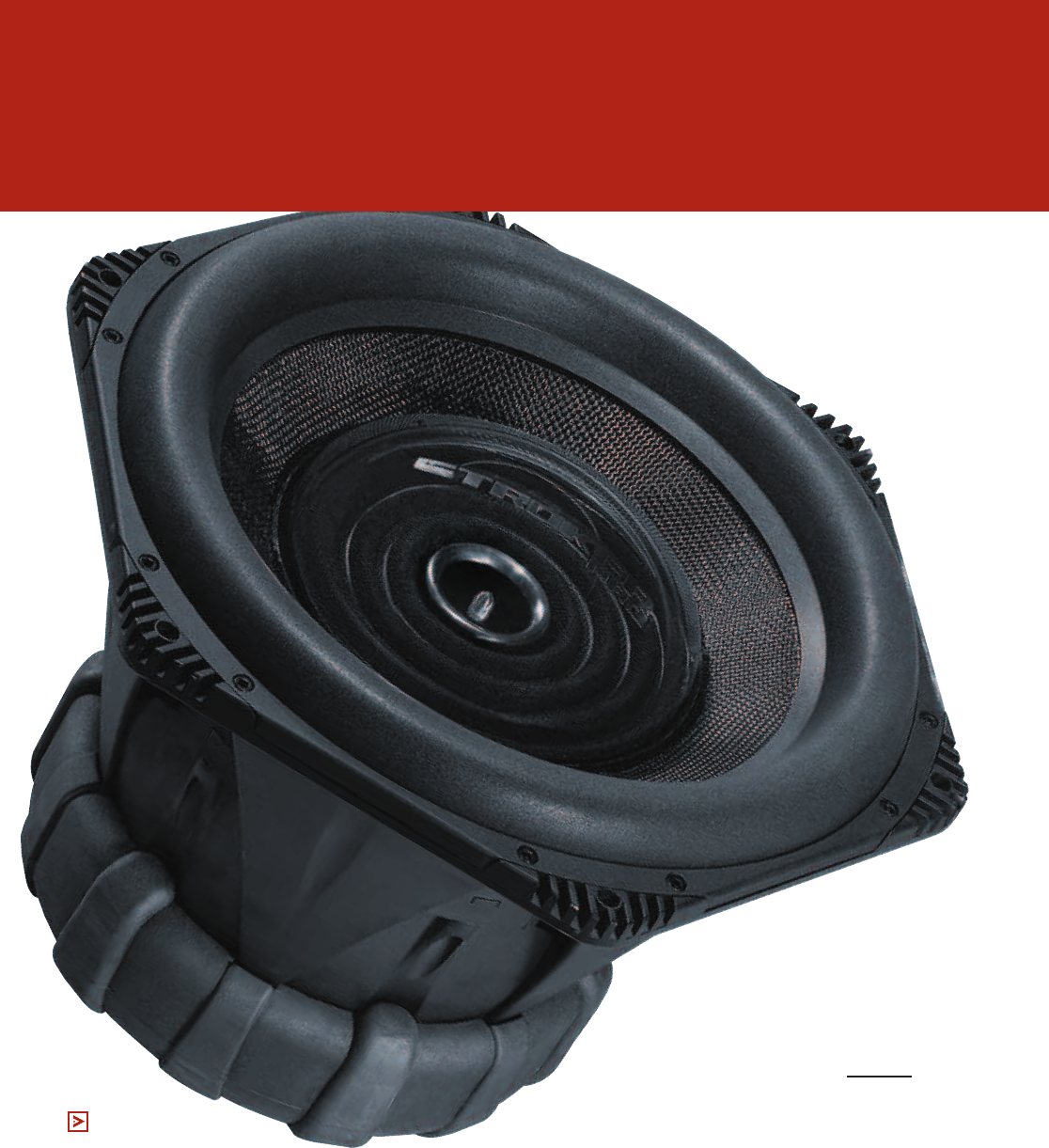
The Stroker Pro cast aluminum frame acts as
both a giant heatsink (an old but good trick) and a
highly effective Faraday
shield or shorting ring (a new
patent-pending trick). The cut-
away drawing (Fig. 1) shows that this woofer not
only has two separate magnets (actually, the lower
magnet is two magnets stacked together, so tech-
nically three magnets), but also two gaps, a tech-
nology known as Multiple Magnet Air Gap (MMAG).
Because of the physical layout of the MMAG motor
format, CV could mount the lower magnet system
to the back of the frame, like a normal woofer,but
turn the frame’s inside diameter upward to form a
shorting ring.
In addition to attenuating nasty eddy currents
produced by the woofer motor and lowering distor-
tion, a large shorting ring also reduces motor tem-
perature by decreasing inductive heating. Figure 2
reveals what an outstanding thermal pathway this
frame makes with the upturned section directly
adjacent to the naked voice coil. The Stroker has
four other thermal pathways: two in the spider-
mounting area and two at the rear of the motor.
There are two sets of vents integrated into the
lower-spider mounting shelf (this woofer has two
mounting shelves for three spiders). A 1/8” gap
goes around nearly the entire perimeter of the
CERWIN-VEGA
STROKER
PRO 15
TEXT: VANCE DICKASON &
ERIC HOLDAWAY
PHOTOS: COURTESY OF MANUFACTURER
MORE
THAN A ONE
NOTE WONDER —
A FRONT-RUNNER FOR
SOUND QUALITY AND SPL
shelf’s 10 1/4” diameter except for the six 1/2”-
diameter mounting posts that it suspends from.
This gives substantial venting area for the airflow
generated by the lower spider motion to move air
past the exposed voice coil and top plate. For the
air caught between the two spiders, there are an
additional six 1/4” x 2” vents. At the back side of the
motor you have a series of six 3/32” diameter
peripheral vents that move air from between the
pole piece and the voice coil out the back of the T-
yoke. Lastly, an aluminum-sleeved 1 3/4” diameter
pole vent powered by the large, moving clear plas-
tic dustcap supports the third spider at the top of
the woofer. Because of this, the sleeve extends to
about double the height of the pole, and thus acts
as another heatsink.
The real heart is the MMAG motor structure.
Since the voice coil is shorter than the combined
length of the two gaps, it appears similar to a con-
ventional underhung voice coil motor. In the con-
ventional motor, as the short coil rides out of a sin-
gle large gap in either direction, the total number of
voice coil turns in the gap decreases and so does
the total Bl, or total horsepower, of the motor.
However with the Stroker Pro dual-gap motor, the
situation is more like hav-
ing two gaps working in
unison. As the number of
turns starts decreasing in
one gap, the number of
turns in the other gap
increases so that the num-
ber of voice coil turns of
wire in the gap stays con-
stant. The cool part is that
it operates in a way that
the two gaps are always
working in conjunction
with each other such that
the number of turns does
not begin decreasing until
the voice coil starts to
leave just one gap. (See
sidebar on pg. 73 for more
information on dual-gap
technology.)
Other features for the Stroker Pro motor include
a forged and CNC-milled single piece T-yoke that
includes an extended pole piece with a pole vent.
This vent gives access to a patented adjustable spi-
der bias system for the top or third spider. All the
original Stroker woofers
had this adjustment sys-
tem; however, it was set
at the factory for maxi-
mum linearity. Stroker
owners found that tweak-
ing this setting enabled
the woofers to play even
louder. Biasing a spider
toward the front side and
causing the voice coil to
be deliberately off-cen-
tered toward the front of
the gap area creates high-
er amounts of even-
ordered distortion (2nd
and 4th harmonics to be
exact). Besides the warm
tones caused by the
biased spider, the
increased even-order distortion also increases the
bass due to a psycho-acoustic phenomenon called
the missing fundamental (which produces percep-
tion of low bass from notes an octave higher). So, if
you want to go from very clean linear bass to an
altered warm bass sound quality, Stroker Pro
woofers come with a tool that allows the user to do
that.
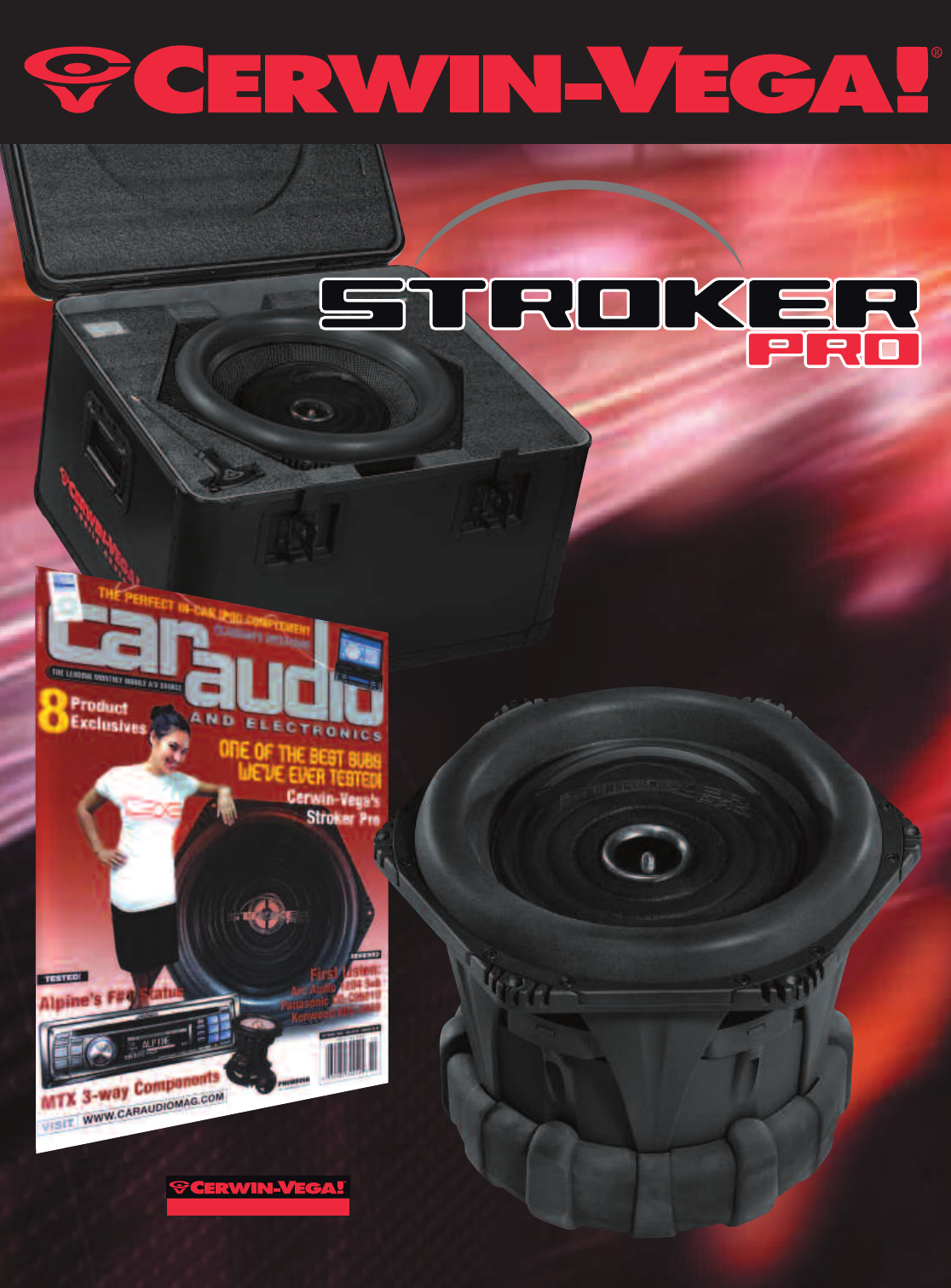
One of the key features to good subwoofer per-
formance is a solidly stiff cone, and the cone in the
Stroker is about as stiff as it gets. Built from layered
carbon graphite and thick paper, the cone is further
reinforced by the large 7 1/2”-diameter clear poly-
carbonate dustcap. Long excursion in a subwoofer
requires the suspension to move long distances.
One solution is incorporating a wide surround that
allows the cone to move further. However, this
decreases the cone area, which in turn requires the
cone to move further! Cerwin-Vega’s patent-pend-
ing solution is SdMaxx (Sd is an engineering abbre-
viation for the area of a cone). Rather than being
low and wide, the polyether foam surround is more
of an ellipsoid shape, tall and narrower. The result is
the same excursion ability, but a greater cone diam-
eter and area. The other part of the SdMaxx system
is an attachment design that allows the entire cone
Figure 1
Figure 2
assembly to be quickly removed and replaced.
The rest of the assembly consists of the three-
polycotton/conex blend spiders. The two lower spi-
ders (mounted inverted to each other to cancel out
some of the non-linear behavior) are 8 1/2” in diam-
eter while the top spider is about 7” in diameter. All
three are progressive, which means they increase in
stiffness the further out they move in either direc-
tion. The dual four-layer voice coil is wound with
high-temperature copper wire on a black anodized
100mm (3.9”) diameter aluminum former. Voice coil
tinsel leads are connected to dual connecting
blocks on opposite sides of the frame. Each termi-
nal block has two sets of hex screw terminals that
accept up to 14-gauge wire, allowing the Stroker
Pro to be easily configured with the voice coils in
series or in parallel.
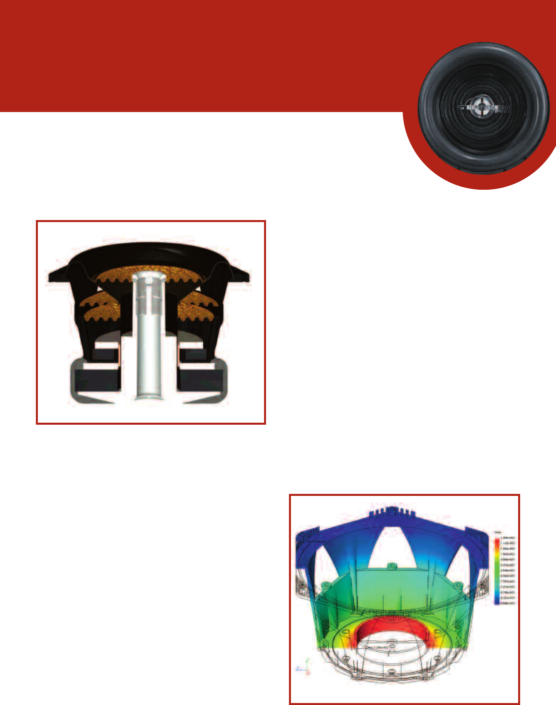
IN THE LAB
Part 1 of the objective measurement consists of
large signal analysis followed by the LEAP 5 analy-
sis. Using the Klippel analyzer (on loan from Klippel
GmbH), Pat Turnmire, CA&E reviewer and CEO of
Redrock Acoustics, performed the large signal
analysis and provided the Bl (X) curve shown in
Figure 3. The black curve is the Bl curve and shows
the motor strength of the woofer as it moves in
both directions from center rest position. The lighter
curve is a type of displacement curve, and if both
curves were identical, the motor system’s motion in
and out of the frame would be perfectly symmetri-
cal. When a woofer is totally linear (linear would
mean that the woofer motion matches the input
signal exactly with no distortion), the Bl curve
should be centered on the 0mm point (where the
cone is positioned when there is no signal) and
symmetrically decrease with the same slopes in
both directions of voice coil travel. When a woofer
exhibits a forward or rearward offset it may indicate
the magnetic and mechanical systems are not
absolutely optimal. If the motor strength decreases
more rapidly in one direction (usually the outward
direction) than the other, the result is increased lev-
els of distortion at high operating levels. It is not
uncommon, however, for a woofer voice coil to be
deliberately offset a few millimeters in order to keep
the motor more linear in the 90-110dB SPL range,
which exactly describes the situation with the
Stroker Pro.
The Stroker Pro Bl (X) curve shows the woofer
voice coil is offset by a fairly trivial 2.5mm rearward
(inward) from its rest position. This Bl curve is a very
symmetrical, broad and flat plateau with nearly
equal slopes in either direction. The displacement
at operating SPL near Xmax is nearly 0mm, so this
is about as good as it gets. Bl can decrease to
approximately 70% of its small signal value and the
driver will still function in a satisfactory manner, only
with an elevated level of distortion (about 20%).
Since this is not really perceivable, it’s really not a
subjective problem. The 70% of maximum Bl dis-
placement limit for the Stroker Pro is 36.3mm,
4.8mm more than the physical Xmax of 32mm.
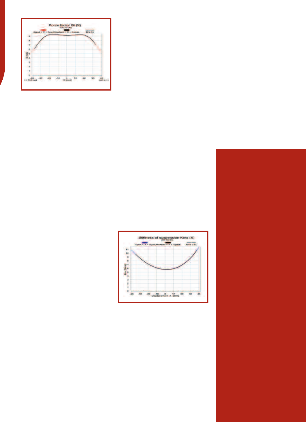
This subwoofer’s Kms(x) or Stiffness of
Suspension curve (see Fig. 4) likewise exhibits very
good symmetry in both directions of travel. The off-
set is a negligible 0.5mm rearward at the rest posi-
tion and transitions to about 2mm of also not-so-
significant forward offset as it reaches the physical
Xmax of the woofer. The compliance limit for the
suspension when it drops to 50% of its rest value is
greater than 38.1mm. Both “limit” numbers, Bl and
compliance, represent the level at which distortion
climbs to 20%, which is a realistic criteria for sub-
woofers given the ear’s lack of sensitivity to distor-
tion at low frequencies.
Next I generated the T/S (Thiele/Small) parame-
ters for the Stroker subwoofer. Following my usual
speaker geek test procedures, I used a LinearX
LMS (Loudspeaker Measurement System) analyzer
and VIBox for measuring dynamic impedance
(impedance at different voltages). Testing is accom-
plished by performing a series of voltage and cur-
rent sweeps that are later converted to multiple
voltage impedance curves. With the driver clamped
to a rigid test stand, measurements were made at
1V, 3V, 6V, 10V, 15V, 20V, 30V and 40V. Rather than
use an added mass or test box method to find the
Vas (volume of air equal to the driver compliance) of
this driver, the measured weight of the cone body
(with 50% of the surround and 50% of the three
spiders removed) was used instead. This group of
multi-voltage impedance curves was copied into
the LEAP 5 software and the parameter model
derivation utility was used to produce the T/S para-
meters shown in the data chart. These numbers
were then used to generate the computer box sim-
ulation data provided in the Data Chart.
The Stroker Pro Thiele/Small parameters shown
in the Data Chart were used to produce computer
box simulations using the Leap 5 Enclosure Shop
software. The software was configured to simulate
the woofer’s low-frequency performance in the
same size boxes recommended in the Stroker Pro
manual, a 2.7ft3sealed box with no fill material and
a 3.0ft3ported box tuned to 36Hz with two 4” diam-
eter vents and also with no fill material. The LEAP 5
graph curves in Figure 3 show the SPL at 2.83 volts
(black curves) in half-space, 2.83 volts in an aver-
age 154ft3car compartment (blue curves), and at
the SPL at a power level required to get maximum
linear excursion (red curves, also half-space). The
sealed box curves are solid lines and the ported
enclosure curves are the dashed curves. The 2.83-
volt results produced an F3 of 43Hz for both box
types. Increasing the simulated input voltage for the
2.7ft3sealed box computer simulation to 150 volts
increased excursion to the Xmax +15% level and
pushed the SPL to a seriously devastating 126dB.
The 3.0ft3vented box computer simulation took
126 simulated volts to drive the Stroker Pro to just
beyond Xmax (Xmax + 15% or 36.8mm for the 15”
Stroker woofer) and resulted in an SPL of an
extremely loud 128dB! This monster definitely
Figure 3
Figure 4
Brand:Cerwin-Vega
Model:Stroker Pro 15
MSRP: $1,699.00
Warranty:1 year parts and labor
MECHANICAL SPECIFICATIONS
Weight 68.3 lbs.
Rear Mounting Clearance 9.75”
Woofer Magnet Dim. (dia. X ht. in mm) 260 x 20 x 2,
200 x 20
Voice Coil Diameter 100mm (3.93”)
Voice Coil Winding Layers 2x2 (two, two-layer coils)
MEASURED T/S PARAMETERS
Nominal Impedance (ohms) 4
Revc (ohms) 3.65 (both 1.83-ohm voice
coils connected in series)
Sd (cone area in square meters) 0.087
Bl (motor strength in Tesla Meters) 22.2
Vas (in liters): 40.0
Cms (micrometers per Newton): 37.4
Mms (grams): 468.1
Fs (Hz): 38.7
Qms: 4.47
Qes: 0.83
Qts:0.70
POWER AND EXCURSION DATA
Sensitivity (2.83V/1M in dB): 86.1 series/92.1 parallel
Continuous Power Handling (watts RMS): 2,500
Peak Power Handling (watts): 5,000
Xmax ([coil length – gap height]/2 in mm): 38.6
COMPUTER SIMULATION DATA
Enclosure size for simulation (cubic feet)
Sealed: 2.7 (0% fill)
Vented: 3.0 (0% fill) tuned to 36Kz
-3dB (F3) at 2.83V
Sealed: (Qtc=0.93): 43.0Hz
Vented: (Qtc=0.93): 43.0Hz
Voltage to achieve Xmax + 15%
Sealed: 150V
Vented: 126V
SPL at Xmax + 15%: (36.8mm)
Sealed: 126dB
Vented: 128dB
DATA CHART
needs to be
treated with respect.
The Stroker Pro is an amazing exercise in max-
imum potential, and while I don’t think this is every-
man’s subwoofer, for those who want to join the
Cerwin-Vega “loud and proud” tradition, it’s a very
serious piece of equipment. The engineering
integrity of the product is impressive and it has the
features required for producing extreme SPL in a
car (something to be very careful with if you value
your hearing). Given the ability to modify the sound
quality with the spider-adjusting tool, my guess is it
will come off well in the listening test. I’m as curious
as everyone else to know if a woofer that measures
this well sounds as good as it looks. —VD
SUBJECTIVE
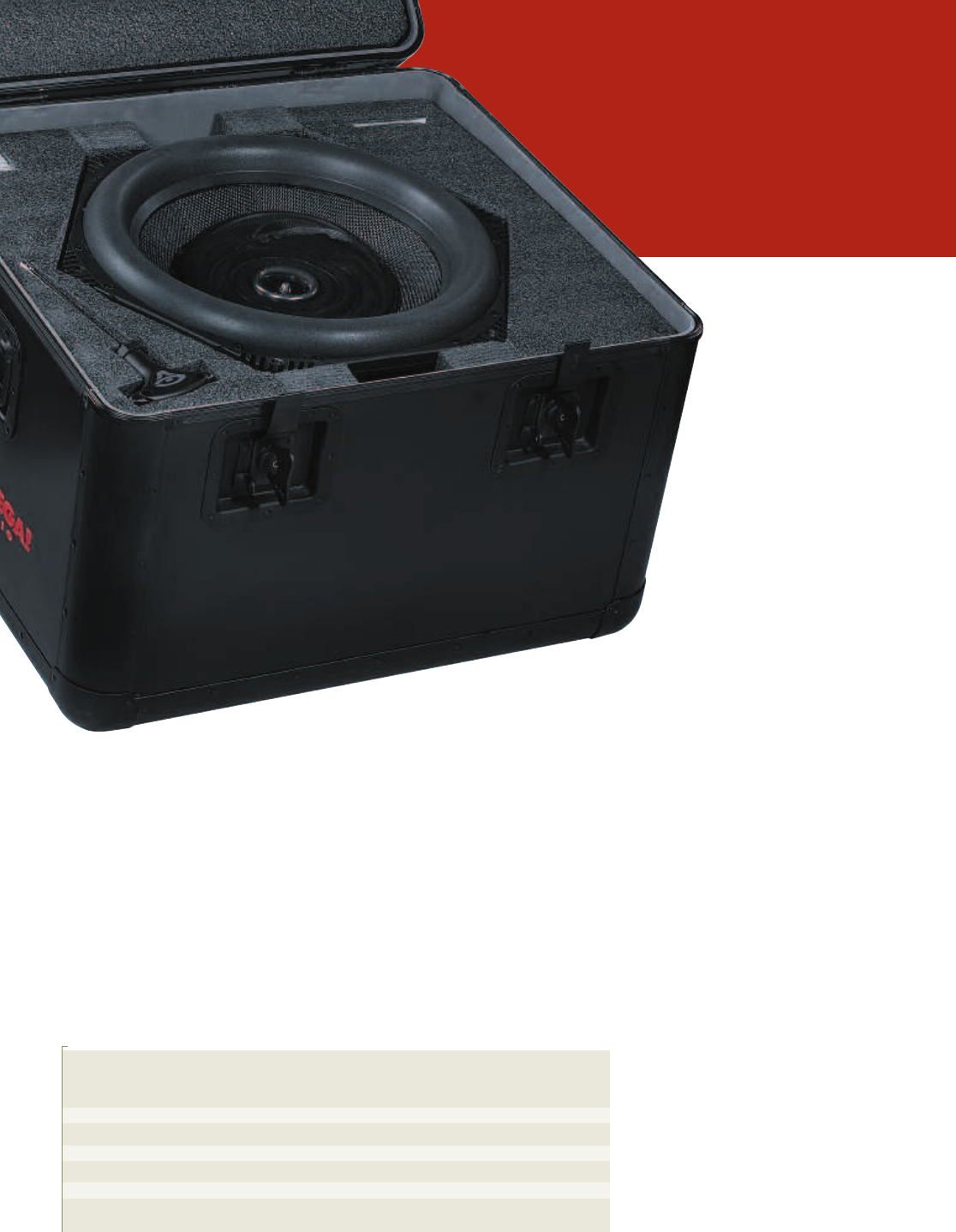
The Cerwin-Vega Stroker Pro 15 arrived on my
doorstep in an Anvil-type case with steel flip-up
handles, just like those used to carry concert gear.
Opening the box I was blown away—the sub-
woofer itself looks fantastic. It’s tall, massive and
damn near 70 lbs.! But it’s the clear dust cap that
captures your attention, allowing you to view the
front spider and the carbon-fiber cone structure
beneath. Beautiful!
Once I got the sub out of its case (with a little
help), I quickly pulled out the instruction manual to
see what the power handling was. I damn near fell
off my stool when I read the 2,500 watts RMS
power figure and the mind-bending 5,000-watt
music rating! But this technological wonder doesn’t
come cheap. As a matter of fact, the Stroker Pro 15
is the most expensive subwoofer I have put through
its paces on these pages with a stag-
gering retail price of $1,699.00.
INSTALLATION
A quick call to Cerwin-Vega got me to
Bob Diamond, CV’s senior design engi-
neer. He recommended I use a sealed
enclosure with an internal volume of 2.7ft3
for the best overall sound quality. Jayson
Olson, master installer at Speaker Works,
was enlisted to build this special enclosure.
The enclosure would be constructed out of two
layers of 3/4” MDF with internal bracing to add
strength and minimize flexing of the enclosure
walls.
Connecting the wires was fairly simple. The Pro
15 uses heavy-duty metal blocks with Allen head
set screws to lock the wires in. The subwoofer’s
dual 2-ohm voice coils were wired in parallel for a
1-ohm load.
Mounting the subwoofer into the enclosure was
a bit tricky. First, you are dealing with a front panel
on your enclosure that is twice your regular thick-
ness and Cerwin-Vega supplies these threaded
steel plates and cap screw bolts to hold the Stroker
in. My guys predrilled the holes in the box’s face
and then glued the threaded steel plates into posi-
tion. Remember, this is a large and heavy enclosure
at an estimated 70 lbs. Combine that with the Pro
15 and we’re dealing with approximately 140 lbs.
It was time to see if we could fit this behemoth
into my Scorched-Earth Black Ford F-350 truck.
There was no way to place it in my normal location
on the floor, so we placed it carefully on the rear
seat. We tried the Stroker facing up and forward,
pointing left and right, but it did not sound correct.
With the enclosure on the rear seat, my seating
location was in a null point and the bass response
was pitiful at best. If I put my head up by the steer-
ing wheel, bass level increased exponentially. I
flipped the polarity of the Stroker, which did not
help, so it was back to the drawing board. Our
solution was to pull the rear seat out of the Ford.
This would allow us to get the Stroker into the loca-
tion that generally works best for most subwoofers
MUSIC SELECTION
Music Points Cerwin Vega
Artist Title Type Possible Stroker Pro 15
Tracy Chapman “Heaven’s Here on Earth” Folk/Rock 12.5 11
Diana Krall “Love Scenes” Jazz 12.5 10.5
10,000 Maniacs “Peace Train” Pop Rap 12.5 11
Usher “Intro” & “Yeah!” Pop Rap 12.5 10.5
Total 50 43
Ratings: 01 Poor 06 Average 12.5 Superior
CERWIN-VEGA
STROKER
PRO 15

in my truck.
The acoustic
match greatly
improved and
now we had a
great-sounding sub-
woofer (what I won’t do for
CA&E magazine, jeez!).
To power the Stroker Pro 15, I installed a Zapco
C2K-9.0XD amplifier to run it. The 9.0XD features a
24dB-per-octave crossover. With the 1-ohm
impedance of the driver, this Zapco will deliver
2,000 watts of power. The front half of my reference
speaker system consists of a pair of USD Audio B-
72Pro WaveGuide separates. I power these with a
Zapco C2K-6.0X amplifier at 150 watts per chan-
nel. The built-in highpass crossover filter was used
to block the bass to the component system. These
amps are fed via Zapco’s Symbilink balanced line
driver SLB-U. There are no other signal processors
in the signal path.
LISTENING
After four hours of break-in time I inserted a
favorite track—Tracy Chapman’s “Heaven’s Here
on Earth.” This subwoofer goes from very low fre-
quencies all the way up the scale smoothly without
drawing attention to itself. The bass imaging was
extremely good. The bass line always stayed up
front and did not pull to the rear of the vehicle at any
point. The bass drum was tight and the bass guitar
smooth and proper. That’s what’s so intriguing
about the Stroker Pro. There is nothing faint about
the looks of this subwoofer, indicating that it could
not be anything less than a brute, yet it had an artic-
ulate and delicate reproduction quality when the
music called for it. And, it had no trouble replicating
layered bass lines. Overall, each instrument stayed
well defined and taut.
On Diana Krall’s Love Scenes album, the stand-
up bass note changes were clear and well defined.
The note-to-note levels were equal and at no time
were they out of proportion to each other. The bass
plucks were very punchy and taut. This subwoofer
is no one-note wonder. It accurately reproduces the
frequency changes up and down the scale from the
string bass to the guitar and the drum kit. It was
very snappy and tight with excellent control. The
Pro 15 exhibited no blooming in the upper bass fre-
quencies like many of the other subs I have tested.
A great benefit to using a large diameter sub-
woofer like this one is how well it energizes the inte-
rior of your vehicle at really, really low frequencies.
Case in point, I had to remove my garage door
opener and sunglasses from their usual perch over-
head at far lower volume levels because they were
rattling almost instantly.
I played the 10,000 Maniacs remake of “Peace
Train” next. It opened with a bass drum kick that
was very low in frequency. Many subwoofers will do
an adequate job on this passage, but the Stroker
Pro 15 really got the job done. Each kick of the bass
drum was sharp, solid and deep. This track illus-
trated the performance gains that large format sub-
woofers have over smaller subwoofers.
Wrapping up, I put in Usher’s latest album and
cranked up the “Intro” track that leads into the track
“Yeah!” “Intro” uses mostly acoustic instruments
with super dynamics and at 0:23 secs into it, the
Stroker punched out a super tight, loud bass line
that was still very realistic sounding. On “Yeah!” it
simply laid down powerful, pumping bass that went
down to the lowest bass notes clearly. Even on this
repeating boomfest, the bass image stayed up
front, solid and fixed.
CONCLUSION
The more I listen to the Cerwin-Vega Stroker Pro
15, the more I like it. It is the best all-around large-
format subwoofer that I have tested by a large per-
centage. It did not matter what type of music I
played, the Stroker Pro 15 made it sound correct
and good. It does its job at all volume levels and
can handle fantastically high amounts of power.
This thing is very expensive, but its performance is
exceptional! Looks like I am going have to do some
begging to get a couple for our VW Beetle show
car. Hey, Mr. Diamond! We need to talk. —EH
SUBJECTIVE SCORE CHART
Points Cerwin-Vega
Possible Stroker Pro 15
Overall Sound Quality 50 45
Tonal Balance 10 08
Low-Frequency Extension 10 09
Clarity at Low Volume 10 08
Clarity at High Volume 10 09
Impact 10 09
Total Subjective Score 100 88
Ratings: 00 Poor 05 Average 10 Superior
CERWIN-VEGA
STROKER PRO 15
If you were to look at the Stroker’s motor in
conventional terms, and consider the distance
from the outside of one gap to the outside of the
other, a distance of 44mm, as one long gap and
figured Xmax based on this and the voice coil
length (remembering that Xmax is voice coil
length minus gap height and that number divided
by 2), which is 38mm for the Stroker Pro, then
the Xmax would only be a silly 3mm. However,
when you consider the dual 12mm gap aspect of
this motor, the Xmax number is really 32mm. And
if you consider the actual Bl curve of this monster,
it’s really more like 36.8mm, which is the manu-
facturer’s Xmax specification for this woofer.
There are a number of positive aspects to this
dual-gap technology, the biggest being the enor-
mous excursion potential. For a given coil length,
the dual gap motor will have 2.5 times more
Xmax than a conventional single gap motor. For
example, a 38mm voice-coil length with a single
12mm gap would have an Xmax of 14mm, com-
pared to the 32mm of the Cerwin-Vega dual-gap
woofer. The other benefit has to do with how
constant Bl is at high SPL levels. Many conven-
tional woofers have a more or less “bell” shaped
Bl curve, which means that as they start operat-
ing at maximum SPL levels, the Bl or motor drive
level will begin decreasing rapidly. This coupled
with the elevated voice coil temperatures mean
that the effective box Q and F3 numbers are gen-
erally higher than at low SPL levels. Effectively,
this suggests that the really low bass tends to go
away somewhat when you get extremely loud
with most subs. With the Stroker Pro, the Bl
curve is very flat and extended and the result is
that the motor does not exhibit as much box Q
and F3 shift as is normally experienced at high
SPL levels. While this extra high output stability
is primarily due to the flat Bl characteristics of the
Stroker Pro, some of this stability can be attrib-
uted to its excellent thermal cooling characteris-
tics.
SPL in car measurement at 2.83 volts, 1 meter – with
Bruel & Kjaer Type 2231 Level Meter set to Un-weighted,
SPL and Fast.
20Hz > 90.6dB
40Hz > 93.4dB
80Hz > 94.6dB
Max SPL > 136.3dB
The Max SPL measurement was taken using only 2,000
watts. At 5,000 watts, a gain of 3-5dB is conceivable.
XMAX AND DUAL-GAP TECHNOLOGY
Posted with permission from the September 2005 issue of Car Audio and Electronics ® www.caraudiomag.com. Copyright 2005, PRIMEDIA Inc. All rights reserved.
For more information about reprints from Car Audio and Electronics, contact Wright’s Reprints at 877-652-5295
