CETIS EXA100 Wireless AP User Manual Users manual
Cetis, Inc. Wireless AP Users manual
UserManual.wiki
>
CETIS
>
EXA100 User Manual
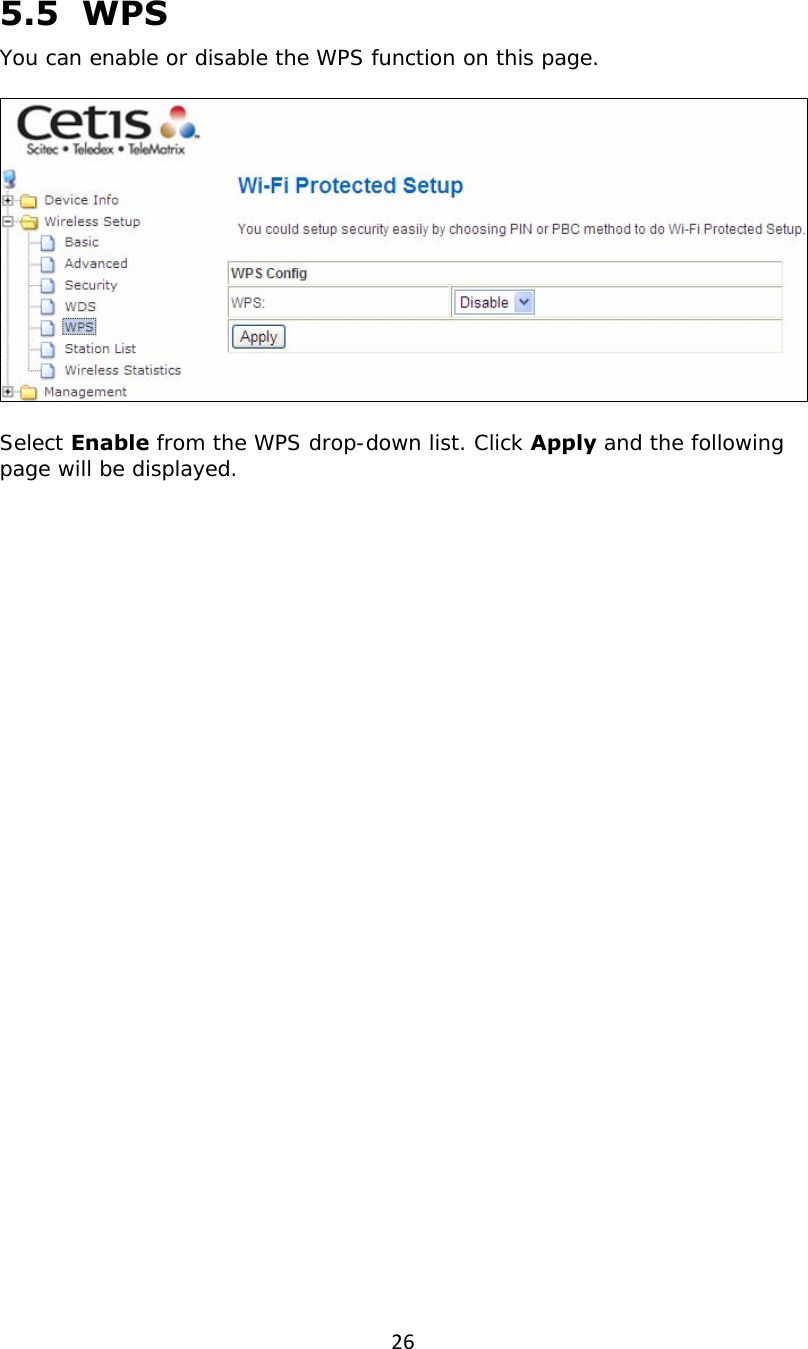
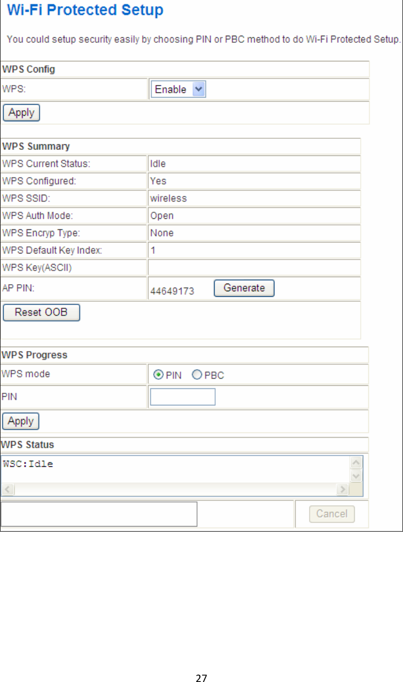
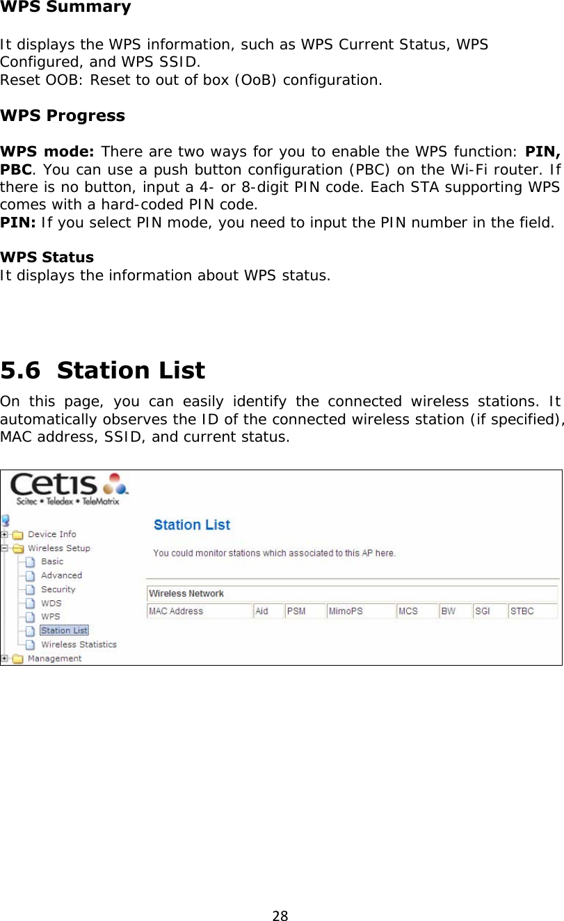
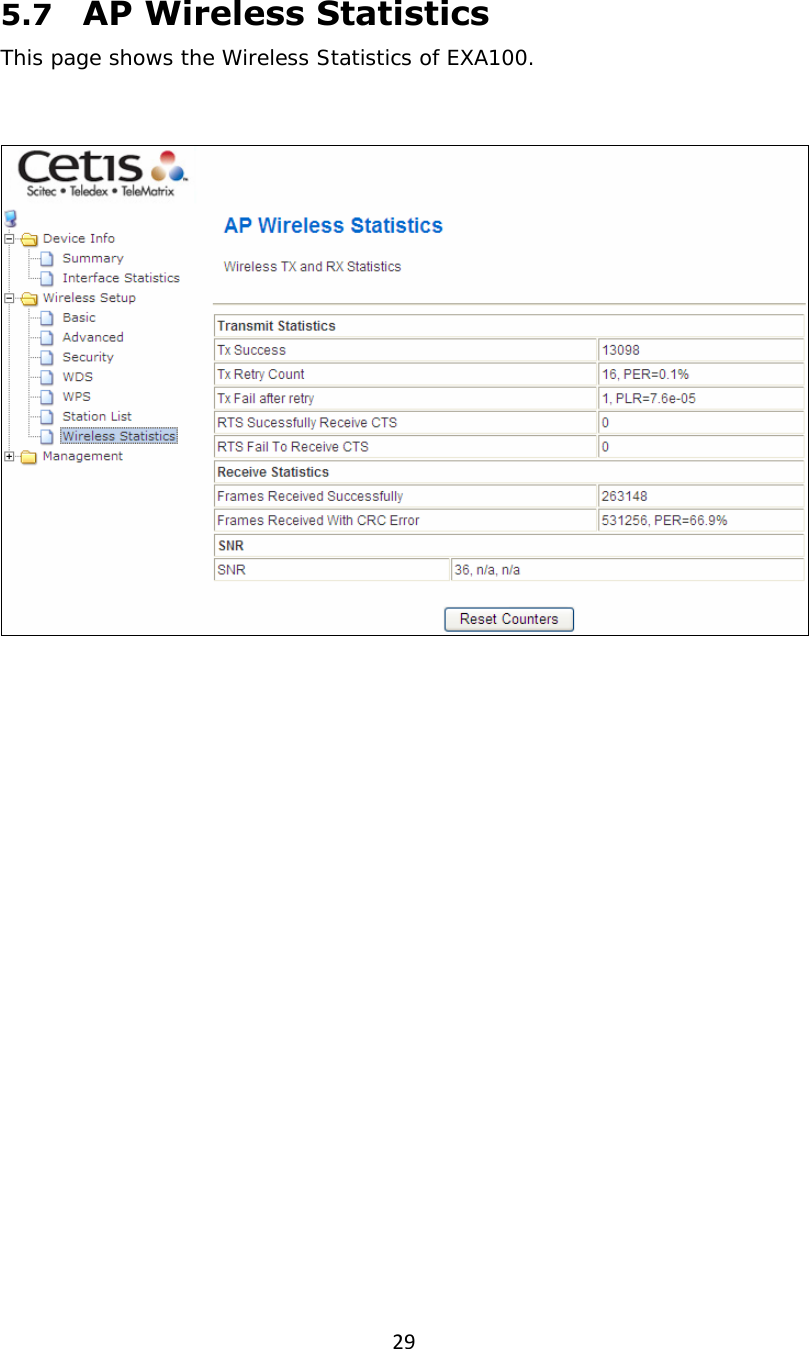
5.User's manual
Navigation menu
Upload a User Manual
Namespaces
Wiki Guide
HTML
PDF
Info
Views
User Manual
Discussion / Help
Navigation
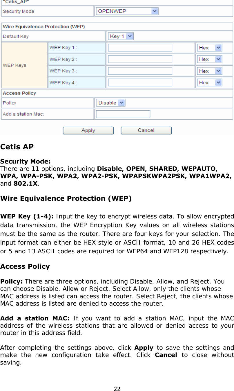
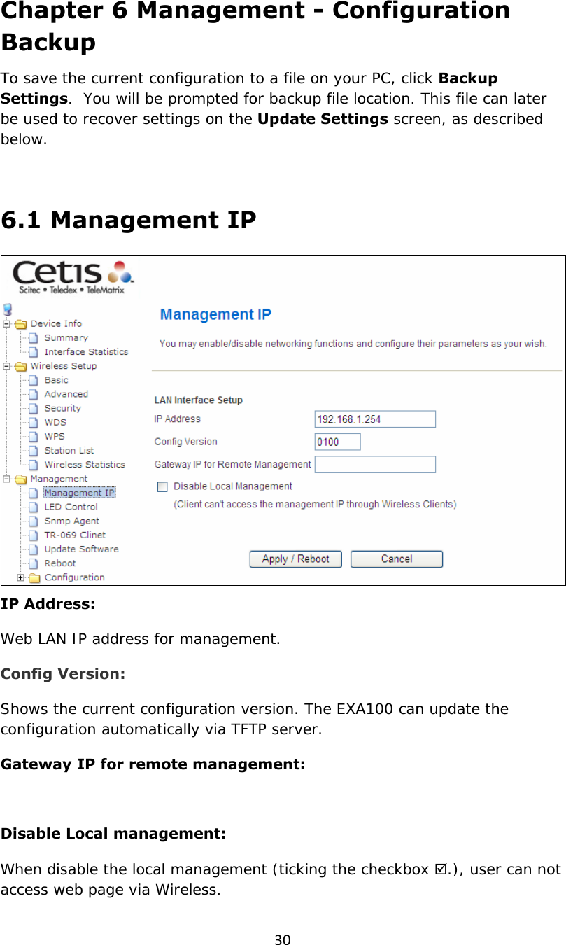
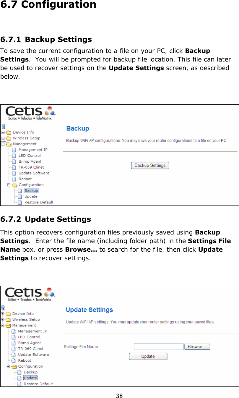
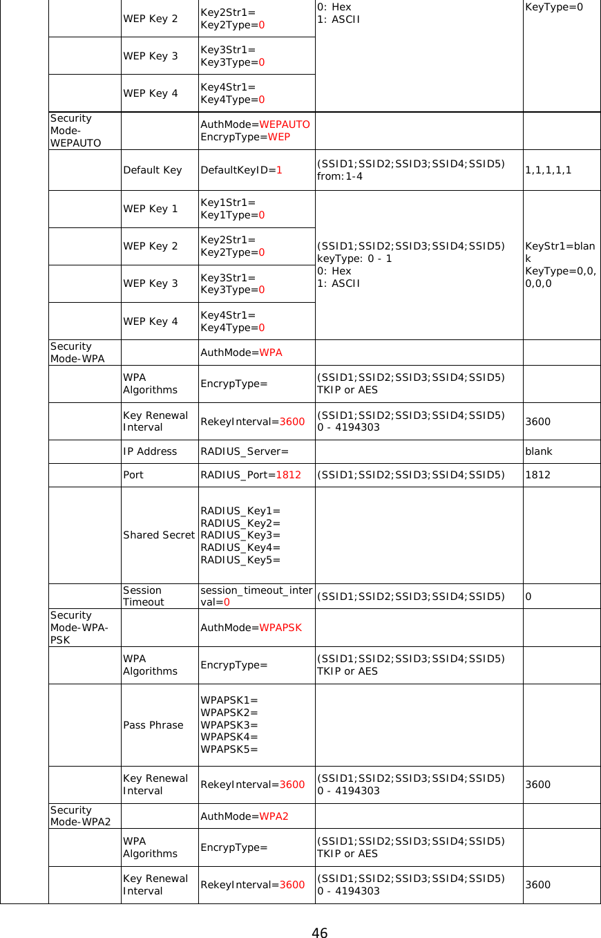
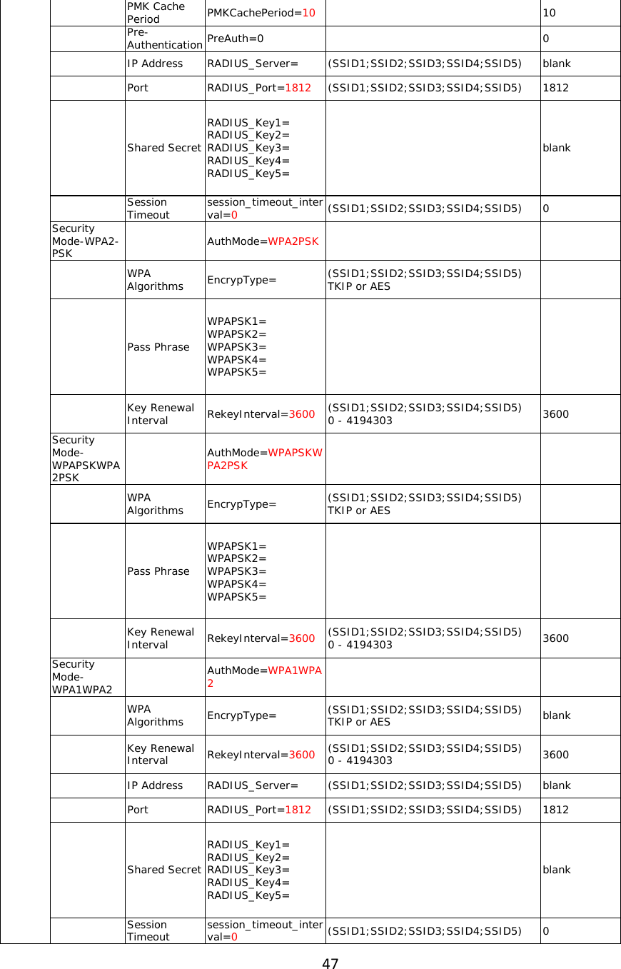
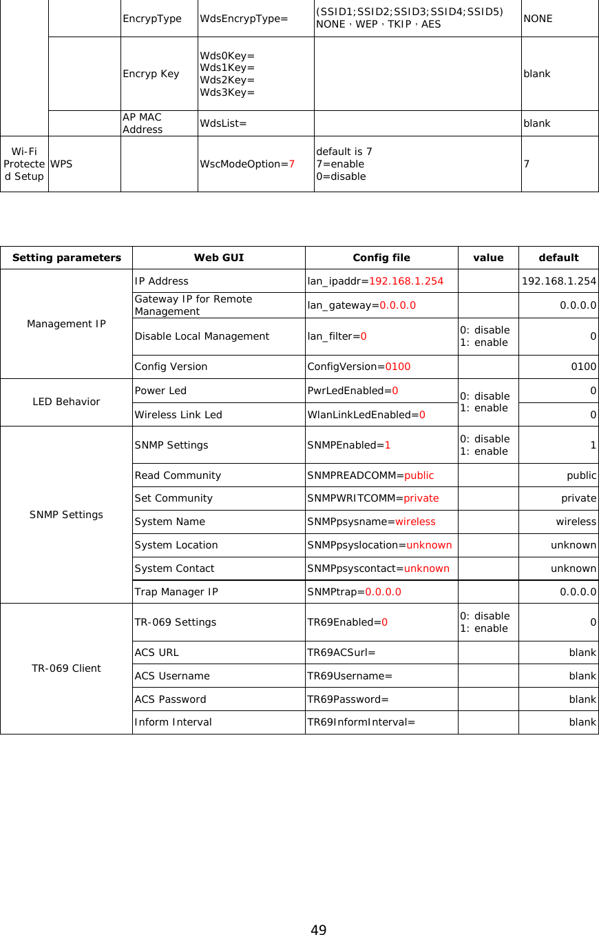
![215.3 Security Choose Wireless Settings>Security and the following page will be displayed. It allows you to modify the settings to prevent unauthorized accesses. Select SSID SSID choice: Select SSID from the drop-down list. “default” Security Mode: There are 11 options, including Disable, OPEN, SHARED, WEPAUTO, WPA, WPA-PSK, WPA2, WPA2-PSK, WPAPSKWPA2PSK, WPA1WPA2, and 802.1X. [EXAMPLE] Take Open WEP for example. Select Open WEP from the Security Mode drop down-list. The following page will be displayed.](https://usermanual.wiki/CETIS/EXA100/User-Guide-1860452-Page-22.png)