Ceyon Technology REM125-5 RF-ID SYSTEM User Manual
Ceyon Technology Co., Ltd. RF-ID SYSTEM
USERS MANUAL

CEYON
RF-ID System
MANUAL

Contents
RF-ID Reader MANUAL ......................................................................................................... 5
1. REM125 Series ................................................................................................................ 6
1.1. REM125 Series Specification ............................................................................................. 6
1.1.1. Product specification........................................................ 6
1.1.2. Environment specification................................................ 6
REM125 Series Parts ..................................................................................................................... 7
1.1.3. REM125 Series Front ...................................................... 7
1.1.4. REM125 Series upper section......................................... 8
1.1.5. REM125-5 lower section.................................................. 8
1.2. REM125 Series installation................................................................................................. 9
1.2.1. Caution during REM125 Series installation..................... 9
1.3. Power connection ............................................................................................................... 9
1.3.1. When the power is supplied normally.............................. 9
1.3.2. When the power is not supplied normally, .....................10
1.3.3. Check the followings...................................................... 10
1.4. ANTENNA Connection ...................................................................................................... 10
1.5. Communication Line Connection.................................................................................... 10
1.5.1. RS-232 Serial Cable Connection Road......................... 10
1.5.2. RS-422 Serial Cable Connection................................... 11
1.5.3. RS-485 Serial Cable Connection................................... 12
1.6. Menu ................................................................................................................................... 13
1.6.1. REM125 Series Menu Tree ........................................... 13
1.6.2. REM125 Series Normal Operation ................................ 14
1.6.3. REM125 Series Configuration ....................................... 14
1.6.4. REM125 Series Test (Trial mode).................................. 18
1.7. Host Communication ........................................................................................................ 18
1.8. Recognition Test ............................................................................................................... 18
1.9. Problems and solutions.................................................................................................... 20
1.9.1. Power-related problems................................................. 20
1.9.2. Problems on the connection between the networks...... 20
1.9.3. Operation Related problems.......................................... 20
RF-ID ANTENNA MANUAL................................................................................................ 22
2. EA125C........................................................................................................................... 23
2.1. EA125C Specifications ..................................................................................................... 23
2.1.1. Product Specifications ................................................... 23
2.1.2. Environment Specifications............................................ 23
2.2. EA125C Parts..................................................................................................................... 24
2.2.1. EA125C Front Section................................................... 24
2.2.2. EA125C lower parts....................................................... 25
2.3. EA125C Installation........................................................................................................... 25
2.3.1. Caution during E A125C Series installation................... 25
2.4. EA125C Communication Line Connection ..................................................................... 26
2.4.1. Caution during cable connection. .................................. 26
2.5. EA125C operation ............................................................................................................. 27
2.6. EA125C Problems and solutions..................................................................................... 27
3. EA125S........................................................................................................................... 28
3.1. EA125S Specifications...................................................................................................... 28
3.1.1. Product Specifications ................................................... 28
3.1.2. Environment Specifications............................................ 28
3.2. EA125S Parts ..................................................................................................................... 29
3.2.1. EA125S Front Section ................................................... 29
3.2.2. EA125S lower part......................................................... 29
3.3. EA125S Installation........................................................................................................... 30
3.3.1. Caution during EA125S installation ............................... 30
3.4. EA125S communication Cable Connection ................................................................... 31
3.4.1. Caution during cable connection ................................... 31
3.5. EA125S operation.............................................................................................................. 32
3.6. EA125S Problems and solutions..................................................................................... 32
Supplement .......................................................................................................................... 34
Supplement 1: Communication with the Host .................................................................. 35
4. Reader Operation........................................................................................................... 35
4.1. RF mode............................................................................................................................. 35
1.1.1. Verbose mode................................................................ 35
1.1.2. Continuous mode........................................................... 35
4.2. Event report mode............................................................................................................. 35
1.2.1 First talk mode(FT)......................................................... 35
1.2.2 Listen & talk mode(LT)................................................... 35
5. Frame.............................................................................................................................. 35
5.1. Command Frame(Host to Reader)................................................................................... 36
5.2. Response Frame(Reader to Host) ................................................................................... 36
6. Command ....................................................................................................................... 37
4. Frame Communication ............................................................................................................ 41
(1)READ Command Format (08h/2nh command) ........................................................ 41
(2) WRITE Command Format (10h/18h/3nh command) .............................................. 41
Supplement 2: Device Check list ....................................................................................... 42
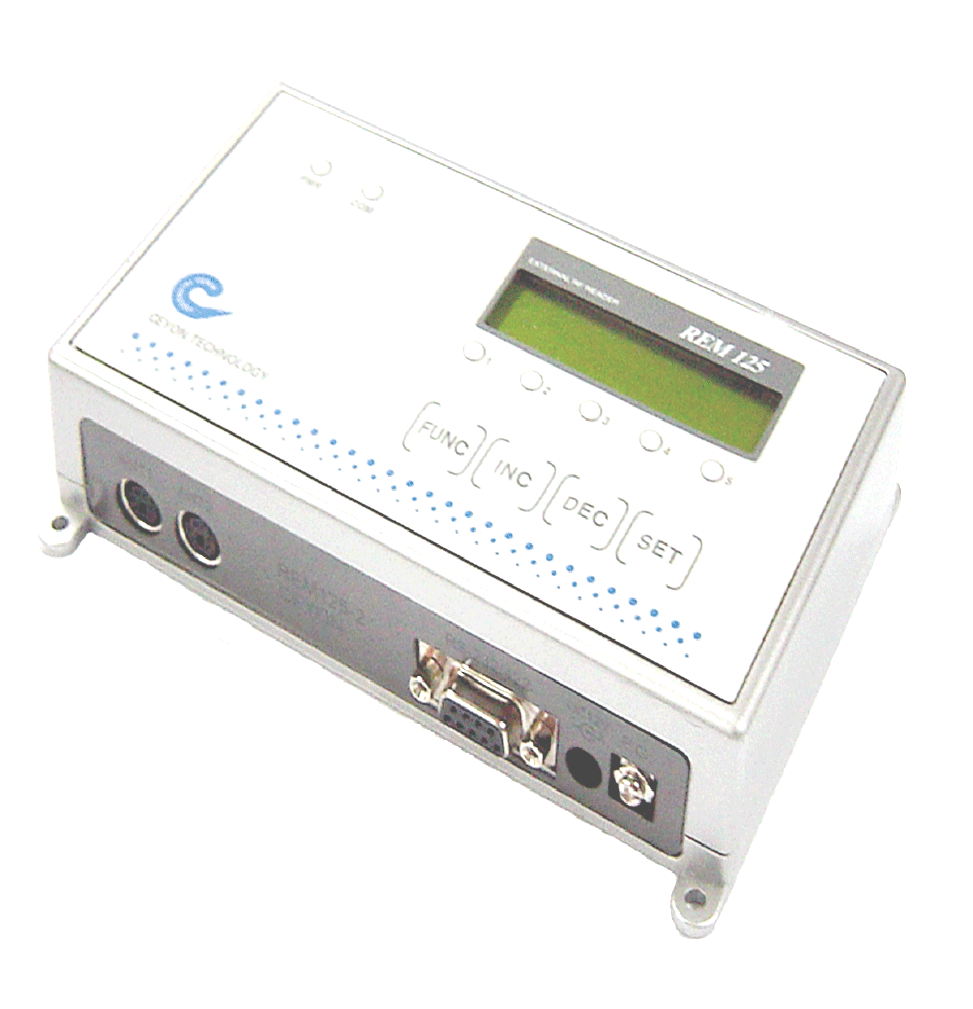
RF-ID Reader
MANUAL
1. REM125 Series
1.1. REM125 Series Specification
1.1.1. Product specification
REM125 Parameter Description
Processor 8 bit Processor
Frequency 125 KHz
LCD type 16*2 line 32 character display
Power DC 12V / 1A
Communication RS232 , RS422, RS485
(Menu Setting)
Dimensions (W)160mm * (L)90mm * (H)35mm
Material ABS
Host Interface 1ea (RS232 , RS422, RS485)
Ant. ch REM125-5 : 5ea
LED display POWER, COM, 1,2,3,4,5
KEY 4 KEYS
1.1.2. Environment specification
Item Specification
Range of operation temperature 0℃ to +65℃
Range of operation humidity 20 % ~ 90 % (No dew forms allowed)
Range of operation steam pressure 1 steam pressure
Range of storage temperature 0℃ to +80℃
Range of storage humidity 20 % ~ 90 % (No dew forms allowed)
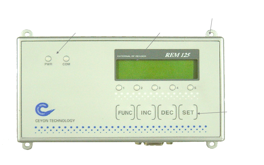
REM125 Series Parts
1.1.3. REM125 Series Front
고정홀
LCD 표시부
KEY부
LED 표시부
1.1.3.1. POWER and LED Lamp
PWR: Show power connection.
COM: Show communication condition with Host.
1.1.3.2. LCD Display
Display current operation mode or Tag ID and setting message.
Tag ID Detection CHANNEL Display
Show the detection of Tag ID from connected antenna channels among others.
REM 1256-2 has 2 operative channels from No.1 to 2 and REM 1356-5 has 5 operative
channels from No.1 to 5.
1.1.3.3. KEY Parts
FUNC : Setting device operation or testing device
INC : Choosing setting type or increasing setting value.
DEC : Choosing setting type or decreasing setting value.
SET : Confirm setting type or setting value.
Led display LCD display
Fixing hole
Key parts

1.1.4. REM125 Series upper section
방열배기구
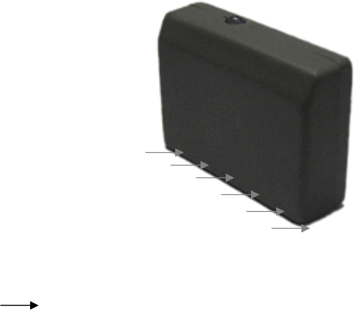
1.1.5. REM125-5 lower section
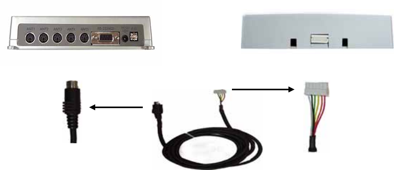
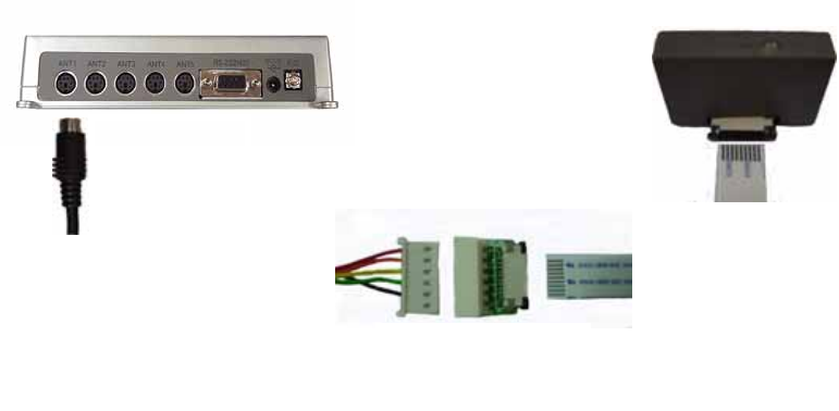
1.1.5.1. ANTENNA Connector
ANT1 ~ ANT 5 : Antenna connector needs 6 pin DIN connector and connected with LED
line to show the operation of LED Lamp
1.1.5.2. D-sub 9 Connector
Connecting to HOST and using RS-232 RS-422, RS-485 interface.
1.1.5.3. DC power connection connector
Using DC12V / 1A, proven linear type adaptor.
** Caution: Must use offered adaptor from CEYON TECHNOLOGY otherwise efficiency
can not be guaranteed
1.1.5.4. Ground connection
Using for safety and prevent from over flow.
Radiation Parts
Antenna connector D-sub9 connector
DC power
Ground connection
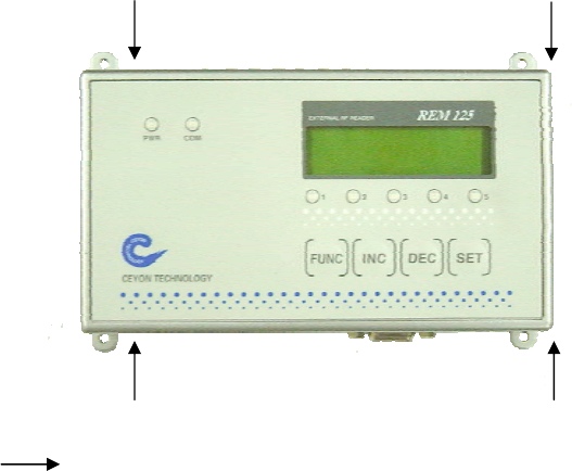
1.2. REM125 Series installation
REM125 Series installation.
REM1356-5 can be installed on any place one can work with drills using M3.5 dish bolt on
marked place( ) and in case of difficulty in drilling on the side of attachment, you can
install it by using special bracket
1.2.1. Caution during REM125 Series installation.
① In case of difficulty in drilling on the face of attachment during the installation, install it
on the designated area using the special bracket.
② Install REM125 Series on the place where the operator can easily perform their
work.
③ Attaching parts or bracket must not use electric wave absorption (magnet, ferrite etc)
and metal material (SUS, AL etc). If you can’t avoid the situation you need
additional consultation.
④ Place antenna in the detection range.
⑤ Do not install near by 125KHz device or LF device.
1.3. Power connection
Insert Adaptor -from CEYON TECHNOLOGY- connector into D.C. terminal.
1.3.1. When the power is supplied normally
After power is supplied, PWR LED shows red color.
There will be 1 second buzz sound.
Operating channels are connected with each LED and once REM1356-5 turned on follows
installed mode automatically.
1.3.2. When the power is not supplied normally,
LED shows nothing.
No buzz sound.
LCD displaies any message.
1.3.3. Check the followings.
Check the power adaptor when operation is not normal.
Check the power is D.C.15v when there is no load on the power.
Confirm on polarity of power. (Make sure that the adapter is from CEYON TECHNOLOGY.)
1.4. ANTENNA Connection
The antenna terminal consists of the 6 pin din jack. The antenna cable is 2M long. In case
of the flat cable needs to be extended, the flat cable 1.5M from us may be used to extend
it for up to 3.5M. The cable may not be cut or remodeled arbitrarily. Since the tag
recognition distance depends upon the size of the antenna or the tag, we have various
kinds of approved antennas in stock. Please consult with our technical staff about the
use and the environment
1.5. Communication Line Connection
Open communication line connection between REM125 Series and HOST. REM1356-5 is
connected to the host through RS-232, RS-422 or RS-485 interface. Check the
connectable interface standard with the host and check the D-SUB 9pin drawing for
connection. Also interface can be easily change by LCD setting menu for user’s
environment.
* RS-232 is setted in the beginning. If you want to chage to RS-422 or RS-485 go to
Configuration -> Serial Interface.
1.5.1. RS-232 Serial Cable Connection Road
Use only pin No.2, No.3, No.5 during RS-232 cable connection and do notconnect the
others since the others can be used for RS-422 and RS-485 connection and for safety.
The wiring diagram of serial cable RS232 is as follows
.
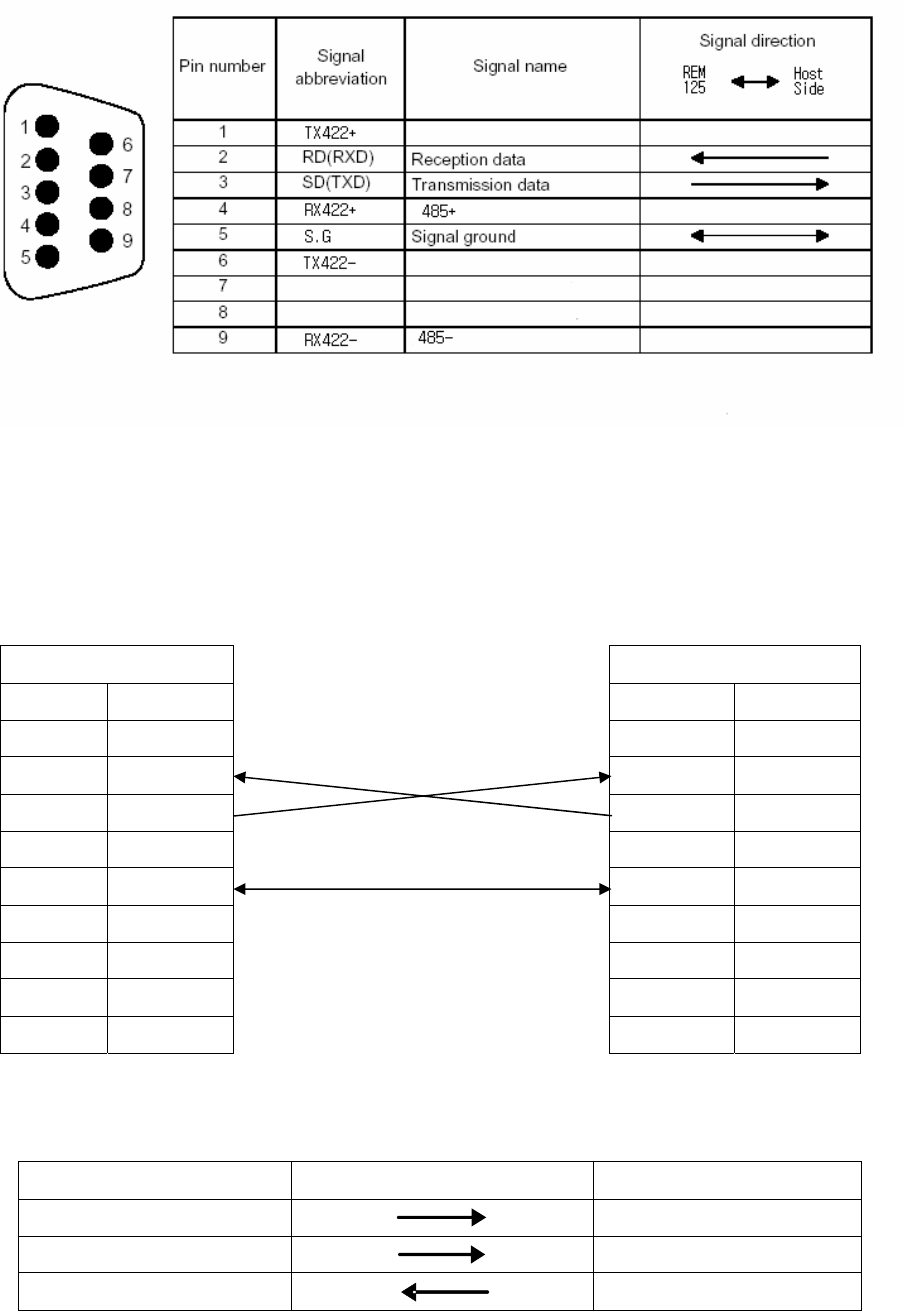
RS232 Cable Connection.
PC REM1356-5
Signal Pin No. Signal Pin No.
CD 1 N.C 1
RD(RXD) 2 RD(RXD) 2
SD(TXD) 3 SD(TXD) 3
DTR(ER) 4 N.C 4
SG 5 SG 5
DSR(DR) 6 N.C 6
RS(RTS) 7 N.C 7
CS(CTS) 8 N.C 8
RI(CI) 9 N.C 9
1.5.2. RS-422 Serial Cable Connection
HOST SIDE REM125 SERIES
TX422+ RX422+
TX422- RX422-
RX422+ TX422+

RX422- TX422-
* In case of need use 330Ω 1/4W resistence
(Case: Communication data loose occured)
1.5.3. RS-485 Serial Cable Connection
HOST SIDE REM125 SERIES
485+ ----Æ 485-
485- Å---- 485+
* In case of need use 100Ω 1/2W resistence
(Case: Communication data loose occured)
1.6. Menu
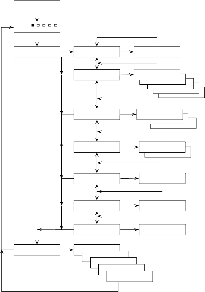
1.6.1. REM125 Series Menu Tree
>>Run
REM125-5
Ceyon Technology
>>Configuration
Test
>>Configuration
Reader Address
Reader Address
>> Addr. : 01
>>Configuration
RF Channel
RF Channel
>> Rfch5 : On
RF Channel
>> Rfch4 : On
RF Channel
>> Rfch3 : On
RF Channel
>> Rfch2 : On
RF Channel
>> Rfch1 : On
>>Configuration
Serial Interface
RS-422
>> RS-422
Serial Interface
>> RS-485
Serial Interface
>> RS-232
>>Configuration
Bau d r at e Serial Interface
>> 19200bps
Serial Interface
>> 9600bps
>>Configuration
Buzzer ON/OFF
Buzzer ON/OFF
>> On
>>Configuration
RF Scan Weight
RF Scan Weight
>> 03
>>Configuration
Make Default
Make Default
>> Press <SET>
Channel [1]
Channel [2]
Channel [3]
Channel [4]
Channel [5]
Menu Tree
REM125 Series
Func
Var iation : I nc or Dec
Confirm : Set
Func
Func
Func
Inc or Dec
Set
Func
Func
Func
Func
Func
Func
Func
Set
Set
Set
Set
Set
Set
Set
Variation : Inc or Dec
Confirm : Set
Var iation : I nc or Dec
Confirm : Set
Variation : Inc or Dec
Confirm : Set
On/Off toggle : Inc or Dec
Confirm : Set
Variation : Inc or Dec
Confirm : Set
Default : Set
Variation : Inc or Dec
Current Channel Test : Set
Apply POWER
Func
Set
Inc or Dec
Inc or Dec
Inc or Dec
Inc or Dec
Inc or Dec
LOCK is setted in the run mode. To change the lock setting push FUNC key for 3 sec
after buzz sound it will be unlocked.
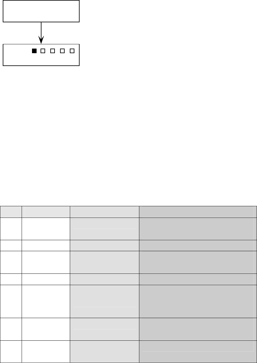
1.6.2. REM125 Series Normal Operation
1.6.3. REM125 Series Configuration
When you are change the setting beep sound will follow and beep sounds have meaning.
Long Beep 3 times: touched non function key.
Short Beep 3 times: setting wass confirmed. (ok)
Short Beep 1 times: setting value was changed.
FUNC KEY for 3 sec change to Configuration mode with long beep.
FUNC mode last for 30sec and back to normal mode after 30 sec.
.
1.6.3.1. REM125 adress installation
Use designated reader address for multy comunication Except POINT TO POINT
order Key input LCD message note
① FUNC >>Configuration FUNC KEY for 3 sec change to
Configuration mode
② SET Lower menu setting
③ INC,DEC
settlement
>>Configuration
Reader Address
Move to pertinent menu by direction
KEY
④ SET Lower menu setting
⑤ INC,DEC
settlement
Reader Address
>> Addr. : 01
Set REM-125’s address by direction
KEY(No need for 1:1 connection)
Changeable range:01~16 default:01
⑥ SET Lower menu Reader adress designated after short 3
beep
⑦ FUNC >>Configuration
Reader Address
Move to upper menu
>>Run
REM125-5
Ceyon Technology
Device always operates at RUN mode. LCD
display scanning channel and deteced data.
( RUN MODE)

⑧ FUNC Test Move to Test mode
⑨ FUNC >>Run Move to Run mode
1.6.3.2. RF Channel installation
REM125-5 can have fast scan cycle when you turn off unusing channels among 5
channels by skipping to next channel.
order Key input LCD message note
① FUNC >>Configuration FUNC KEY for 3 sec change to
Configuration mode.
② SET Lower menu setting
③ INC,DEC
settlement
>>Configuration
RF Channel
Move to pertinent menu by direction
KEY.
④ SET Lower menu setting
⑤ INC,DEC
settlement
RF Channel
>> RfCh1. : On
Set RFCh1 by direction KEY
Changeable range: RfCh1~ RfCh5
Default : All channel On
⑥ SET Lower menu Set On, Off Toggle mode after short 3
beep
⑦ FUNC >>Configuration
RF Channel
Move to upper menu
⑧ FUNC Test Move to Test mode
⑨ FUNC >>Run Move to Run mode
1.6.3.3. Serial Interface installation
REM125 Series has 3 kinds of interface to satisfy various needs. You need to choice
interface and set the interface at REM-125 menu.
order Key input LCD message note
① FUNC >>Configuration FUNC KEY for 3 sec change to
Configuration mode.
② SET Lower menu setting
③ INC, DEC
settlement
>>Configuration
Serial Interface
Move to pertinent menu by direction
KEY
④ SET Lower menu setting
⑤ INC, DEC Serial Interface Choice interface by direction KEY

settlement >> RS-232 Default: RS-232
⑥ SET Lower menu Set On, Off Toggle mode after short 3
beep
⑦ FUNC >>Configuration
Serial Interface
Move to upper menu
⑧ FUNC Test Move to test menu
⑨ FUNC >>Run Move to run mode
1.6.3.4. Baudrate installation
The host makes a choice interface speed and support 9600bps or 19200bps.
order Key input LCD message note
① FUNC >>Configuration FUNC KEY for 3 sec change to
Configuration mode.
② SET Lower menu setting
③ INC, DEC
settlement
>>Configuration
Baudrate
Move to pertinent menu by direction
KEY
④ SET Lower menu setting
⑤ INC, DEC
settlement
Baudrate
>> 9600bps
Choice interface speed by direction
KEY
default: 9600bps
⑥ SET Lower menu Set Host speed after short 3 beep
⑦ FUNC >>Configuration
Baudrate
Move to upper menu
⑧ FUNC Test Move to Test menu
⑨ FUNC >>Run Move to run menu
1.6.3.5. Buzzer ON/OFF installation
REM125 Tag ID detection makes 1 beep sound and you can you can turn the sound
on/off but can not handle control key beep sound.
order Key input LCD message note
① FUNC >>Configuration FUNC KEY for 3 sec change to

Configuration mode.
② SET Lower menu setting
③ INC, DEC
settlement
>>Configuration
Buzzer ON/OFF
Move to pertinent menu by direction
KEY
④ SET Lower menu setting
⑤ INC, DEC
settlement
Buzzer ON/OFF
>> On
Set on/off with direction KEY
default: On
⑥ SET Lower menu Set Host speed with 3 short beep
sound
⑦ FUNC >>Configuration
Buzzer ON/OFF
Move to upper menu
⑧ FUNC Test Move to Test menu
⑨ FUNC >>Run Move to run mode
1.6.3.6. RF Scan Weight installation
Scan weight can adjust channel time posrssesion from 80ms to 170ms. There are 1 to 10
(80ms~170ms). RF can be disturbed by envuroment so scan weight function make quick
detection of Tag Id
order Key input LCD message note
① FUNC >>Configuration FUNC KEY for 3 sec change to
Configuration mode.
② SET Lower menu setting
③ INC, DEC
settlement
>>Configuration
RF Scan Weight
Move to pertinent menu by direction
KEY
④ SET Lower menu setting
⑤ INC, DEC
settlement
RF Scan Weight
>> On
Set scan weight by direction KEY
Changeable range: 1 ~ 10 default: 3
⑥ SET Lower menu Set scan weight with 3 short beep
sound
⑦ FUNC >>Configuration
RF Scan Weight
Move to upper menu
⑧ FUNC Test Move test menu
⑨ FUNC >>Run Move to run mode
1.6.3.7. Factory installation
Back to default value.

order Key input LCD message note
① FUNC >>Configuration
② SET Lower menu setting
③ INC,DEC
settlement
>>Configuration
Make Default
Move to pertinent menu by direction
KEY
④ SET Make Default
>> Press <Set>
Back to default mode
⑥ FUNC >>Configuration
RF Scan Weight
Move to upper menu
⑦ FUNC Test Move to Test menu
⑧ FUNC >>Run Move to run mode
1.6.4. REM125 Series Test (Trial mode)
Checking operation condition before actual operation
order Key input LCD message note
① FUNC Test
Move to FUNC key
② SET Lower menu setting
③ INC,DEC
settlement
Channel [1] Move to pertinent menu by direction
KEY Move to Testing RF CHANNEL
④ SET Channel [1]
K60T0031
Send reading order
Receive data normally
⑤ FUNC >> Run Move to run mode
1.7. Host Communication
REM125 Series allows transmission/reception of the Tag ID and device setting from the
host. For the type and standard of communication with the host, please refer to the
attached protocol.
1.8. Recognition Test
The following diagram shows the normal process flow from power on to tag ID recognition.
Make sure that the system operates according to the diagram before actual use.
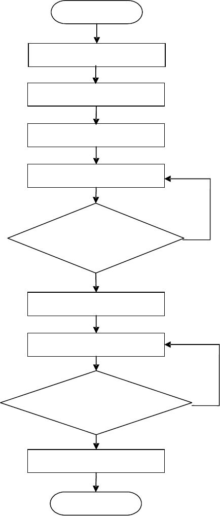
Confirm a supplement of the check list for more description about operation except
above test
Start
Antenna Connection
C
ommun
i
ca
ti
on
line connection
Using Channel
RUN
Are the active
channels set?
Tag Recognized
Data output and transmission
Is the ID identified and
the follow up action performed?
Completed
Yes
Yes
No
No
Power On
1.9. Problems and solutions
Introduce diversity problems and solutions that could happen..
1.9.1. Power-related problems
Q1. After connecting the power connector, LED isn’t on
A1. When this problem occurs, check the followings.
Check the equipment of the power supply. (DC12V / 1A )
Remove the cable from power input port and after 10 seconds reconnect it and restart
REM125.
1.9.2. Problems on the connection between the networks
Q1.When the connection between the host and REM125 cannot be made.
A1. When this problem occurs, checks the followings.
Check again the connection status of all kinds of cables connecting the host and REM125.
Also check if using the private cable or not.
Check the operational status of the host and REM125.
.
Q2. The connection between ANTENNA and REM1356-5 cannot be made.
A2. When this problem occurs, checks the followings.
Check again the connection status of all kinds of cables connecting the REM1356-5and
ANTENNA.
Also check if using the private cable or not.
Check the operational status of REM134and ANTENNA.
1.9.3. Operation Related problems
Q1 The system is not functioning normally .
A1. Check the communication line is properly connected.
Check if the power is normally supplied.
Check LCD display Channel[!] at test mode
* [!]means atenna adress
Q2. . The system does not function normally even after the power and communication are
connected properly.
A2. Check if the proper cable is used.
Check the address is setted corrected.
Turn on the power again.
Check if the command format is correct.
Q3. The error occurs even though the tag is located within the effective recognition
distance.
A3. Turn on the power again.
Check the REM125 operating mode.
If the problem is not solved after above procedure, pull off the power cable after
turning off the system and call SEYON Technology (+82-31-267-1163).

Ceyon RFID 125 Series
APPROVED ANTENNA for RFID System (REM125-5).
Product Name / model name Approved Antenna Model name
EA125-C REM125-5
EA125-S
About the antenna specification, please see the antenna manual.
Caution
Modifications not expressly approved by the party responsible for compliance could void the
user’s authority to operate the equipment.
FCC Compliance Information
This device complies with Part 15 of FCC Rules. Operation is subject to the following two
conditions: (1) This device may not cause harmful interference, and (2) This device must
accept any interference received.
Including interference that may cause undesired operation.
Information to User
This equipment has been tested and found to comply with the limits for a Class B digital
device, pursuant to part 15 of the FCC Rules. These limits are designed to provide reasonable
protection against harmful interference in a residential installation. This equipment generates,
uses and can radiate radio frequency energy and, if not installed and used in accordance with
the instructions, may cause harmful interference to radio communications. However, there is
no guarantee that interference will not occur in a particular installation. If this equipment does
cause harmful interference to radio or television reception, which can be determined by
turning the equipment off and on, the user is encouraged to try to correct the interference by
one or more of the following measures:
- Reorient or relocate the receiving antenna.
- Increase the separation between the equipment and receiver.
- Connect the equipment into an outlet on a circuit different from that to which the receiver is
connected.
- Consult the dealer or an experienced radio/ tv technician for help.
RF-ID ANTENNA
MANUAL
2. EA125C
2.1. EA125C Specifications
2.1.1. Product Specifications
EA125C Parameter Description
Processor 8 bit Processor
Frequency 125 KHz
Dimensions (W)165mm * (L)168mm *
(H)45mm
Material ABS
Reader contact 6 Pin 5268 Connector
Dual LED (RUN,Status)
Display
Buzzer
2.1.2. Environment Specifications
Item Description
Operating Temperature Range 0℃ to +65℃
Operating Humidity Range 20 % ~ 90 % (No dew)
Operating Pressure Range 1 atm
Storage Temperature Range 0℃ to +80℃
Storage Humidity Range 20 % ~ 90 % (No dew)
2.2. EA125C Parts
2.2.1. EA125C Front Section
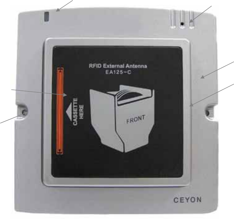
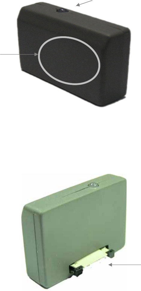
2.2.1.1. LED Part
Show power connection and operation condition.
2.2.1.2. Buzzer display part
2 buzzer sound with detection of tag ID
2.2.1.3. Impact absorption part
Impact absorption is designed to protect atenna from damage between EA125c and
Cassette.
Used silicon pad for the first impact and made cassette guide line for correct direction.
Buzzer hole
Impact absorption
silicon pad
Communication lamp
Impact absorption
part
Cassette
Guide parts
Fixing hole
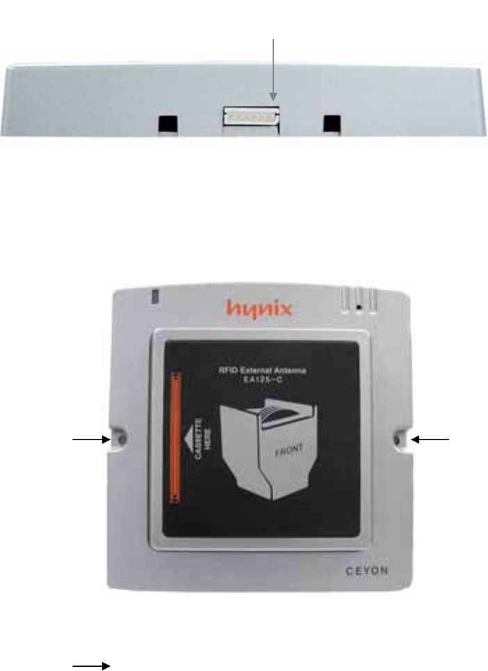
2.2.2. EA125C lower parts
2.2.2.1. Reader connection
Connect EA125C Antenna and REM125 series by cable(Mini Din 6pin +5264 6 pin, 2.5m).
2.3. EA125C Installation
EA125C can be installed on any place one can work with drills using M3.5 dish bolt on
marked place( ) and in case of difficulty in drilling on the side of attachment, you
can install it by using special bracket
2.3.1. Caution during E A125C Series installation
① In case of difficulty in drilling on the face of attachment during the installation, install it
on the designated area using the special bracket
② Install EA125C Series on the place where the operator can easily perform their
work.
③ Chase worker’s moving line before installation and place Tag in the detection
EA125C Connector
range.
④ Install communication line for comfortable place.
⑤ Attaching parts or bracket must not use electric wave absorption (magnet, ferrite etc)
and metal material (SUS, AL etc). If you can’t avoid the situation you need
additional consultation.
2.4. EA125C Communication Line Connection
REM125-5 EA125C
Connect Flat cable with EA1356R and EA1356CV with Pin connector using antenna cable.
2.4.1. Caution during cable connection.
Connect cables after checking connection part and pin before connect to EA125C.
Wrong connection can damage pins.
Hold connector part when you pull out or insert communication cable to protect cable.
Keep away from foreign substance and should not be stock in each connector.
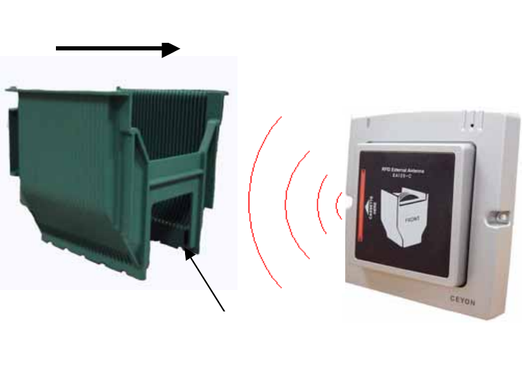
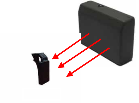
2.5. EA125C operation
Upper picture is about magnetic field radiation. Move Cassette to the center of EA125c
and cassette’s tag will be detected at the middle of EA125-C.
2.6. EA125C Problems and solutions
Introduce diversity problems and solutions that could happen.
Q1. Communication lamp doesn’t work or no buzzer sound after reading Tag.
A1. Check power is supplied normally to REM125-(2)5.
Check cable connection condition between EA1356R and Reader.
Check connector pin and line condition.
Q2. Can’t detect Tag within possible range.
A2. Check EA1356R, CV’s communication lamp has red light.
Check EA125C’s cable connection condition.
Check connector pin and line condition.
Check data input is correct for CassetteTag
If the problem is not solved after above procedure, pull off the power cable after turning off
the system and call SEYON Technology (+82-31-267-1163).
EA125-C
Cassette
진행 방향
Tag
Moving direction
3. EA125S
3.1. EA125S Specifications
3.1.1. Product Specifications
EA125S Parameter Description
Frequency 125 KHz
Dimensions (W)35mm * (L)25mm * (H)10mm
Material ABS
Reader contact 6 Pin FFC Connector 접속
Display Dual LED (RUN,Status)
3.1.2. Environment Specifications
Item Description
Operating Temperature Range 0℃ to +65℃
Operating Humidity Range 20 % ~ 90 % (No dew)
Operating Pressure Range 1 atm
Storage Temperature Range 0℃ to +80℃
Storage Humidity Range 20 % ~ 90 % (No dew)
3.2. EA125S Parts
3.2.1. EA125S Front Section
3.2.1.1. LED Part
Show power connection and operation condition
3.2.2. EA125S lower part
3.2.2.1. Reader connector
EA125S 안테나와 REM125 series를 전용 Cable을 사용하여 접속하기 위한 커넥터입니다.
Connector for connection between EA125s and REM125series
*cable 2 kinds: Mini Din 6pin +5264 6 pin, 2.5m
FFC cable ,1m
TAG detection part
(Internal ANTENNA installation
part)
Condition LED
FFC connector
3.3. EA125S Installation
REM1356-5 can be installed on any place one can work with drills using M3.5 dish bolt on
marked place( ) and in case of difficulty in drilling on the side of attachment, you can
install it by using special bracket
3.3.1. Caution during EA125S installation
① In case of difficulty in drilling on the face of attachment during the installation, install it
on the designated area using the special bracket
② Install EA125s Series on the place where the operator can easily perform their
work.
③ Attaching part must be flat and use special adhesive.
④ Install communication line for comfortable place.
⑤ Attaching parts or bracket must not use electric wave absorption (magnet, ferrite etc)
and metal material (SUS, AL etc). If you can’t avoid the situation you need
additional consultation.
3.4. EA125S communication Cable Connection
REM125-5
EA125-S
통신용 Cable FFC
Cable 변환용 PCB
EA125s is connected to REM125-2(5) with cable through transform PCB. Compare to
EA125c FCCline is 1m added that installation will be easy.
3.4.1. Caution during cable connection
① Check connecting part of EA125C and connector and wrong connection can
damage pins.
② Check transform PCB and EA125S connector before connect to connector
③ Make sure connector jack’s connection not to loose connection.
Communication
cable
Cable transeform PCB
3.5. EA125S operation
CYWT125-H
EA125-S
Upper picture is about magnetic field radiation. Tag shows best efficiency at the
center of EA134, especially best detection range can be guaranteed when Tag’s
the center is located at antenna’s the middle.
3.6. EA125S Problems and solutions
Introduce diversity problems and solutions that could happen.
Q1. Communication lamp doesn’t work or no buzzer sound after reading Tag.
A1. Check power is supplied normally to Reader.
Check connection condition between EA125S and FFC.
Check connector pin and line condition.
Check EA125S, REM125-2(5) and cable transform PCB’s connection.
Q2. Can’t detect Tag within possible range.
A2. Check EA125S communication lamp has red light.
Check EA125S, REM125-2(5) and cable transform PCB’s connection
Check connector pin and line condition
Check data input is correct for Tag
If the problem is not solved after above procedure, pull off the power cable after
turning off the system and call SEYON Technology (+82-31-267-1163).
Supplement
Supplement 1: Communication with the Host
4. Reader Operation
4.1. RF mode
1.1.1. Verbose mode
The Reader recognizes and reads the tag by operating only one channel from those in
waiting mode through the host command (CVR). The channel that is operated in
Verbose mode is activated only the specific scanning duration. If the tag is read within
that duration, the channel stops its operation and returns to the waiting mode. If the
tag is not recognized during the scanning duration, it is also returned to the waiting
mode.
1.1.2. Continuous mode
All channels of the Reader operate for the specific duration (scan weight) set for the
channel and then return to the waiting mode. The next channel is then activated and
goes through the cycle. If there is only one channel, it continuously searches the tag.
4.2. Event report mode
1.2.1 First talk mode(FT)
In this mode, the data is immediately sent to the host when the even (tag read) occurs
to the reader.
1.2.2 Listen & talk mode(LT)
The Reader stores the data in its own memory when the event occurs and sends it to
the host only when requested (CTR). In this case the data is stored in the reader until
the host request.
5. Frame
The communication between the reader and the host occurs through two types of
frames. The type of frame is determined by the transmitting device. The data in the
frame consists of ASCII code. For the numeric data, its hex value is changed to 2byte
ASCII code. The frames are described in detail below.
5.1. Command Frame(Host to Reader)
ENQ(05h)
(1byte)
d.ADD
(2bytes)
CMD
(6bytes)
DF
(0~nbytes)
CS
(2bytes)
Header Data Tail
2.1
ENQ (Enquiry) : This signifies the beginning of the frame and is the ASCII 05H control
character.
d.ADD (Destination Address) : ): It is the reader’s address to send the data or to
accepting data and can be within 00H ~ FFH, set as default (01).
CMD (Command) : Decide reader’s operation and send directly to the host. But the writing
and abnormal response will send back to reader
DF (Data Field) : data
CS (Checksum) : The lowest 1 byte value of the sum excluding CS is changed to 2 byte
ASCII code.
5.2. Response Frame(Reader to Host)
STX(02h)
(1byte)
s.ADD
(2bytes)
ETX(03h)
(1byte)
DF
(0~nbytes)
CS
(2bytes)
Header Data Tail
CH
(2bytes)
2.2
ACK(06h)
(1byte)
s.ADD
(2bytes)
Header
NAK(15h)
(1byte)
s.ADD
(2bytes)
Header
ECD
(2bytes)
Data
2.3
Resposnse frame using for sending control information, reader to host is shown 2.2. This
frame is about Tag’s reade/write(CTR/CTW) and command respond when sending data or
various respond from host request. Control information can be sand following request that
request/response co-work. If there is no response data or error sending ACK or NAK in
2.3
STX (Start TX) : Means Frame start and ASCII 02h’ control character.
ACK(Acknowledgement) : Proper request handle and ASCII 06H’s control character
NAK(Negative ACK) : Fail from request and ASCII 15H’s control character
s.ADD (Source Address) : Reader’s address sending data
CH (channel) : Reader’s channel nember(One reader has several channels and each
antenna called channel. Single antenna always has 1ch. FFH for sending control
information
DF (Data Field) : data
ETX (End TX) : Means end of data and ASCII 03H’s control character
CS (Checksum) : The lowest 1 byte value of the sum excluding CS is changed to 2 byte
ASCII code.
ECD : Signifies ERROR CODE 1 byte and changed to 2 byte ASCII code.
A0H : WRITING FAIL,
A8H : READING FAIL,
80H : CHECKSUM FAIL
88H : Overflow
40H : EEPROM WRITING FAIL
20H: RF Mode error
28H:Event Mode error
10H : Unknown command
18H : Time Out
6. Command
REM125 and WIM125 suport below commands. Each command display as Cxx and here
c means Command. As shown in the table CDM has 3byte and each command cowork
with data.
One important thing is that data’s 1byte Hex transforms 2byte ASCII that 6bytes long in
the frame.
Ex)CCS (08h 03h 01h)will be ‘0’’8’’0’’3’’0’’1’ and become 30h 38h 30h 33h 30h 31h in
the freame.
Such data transforming is applied to all field as ENQ, STX and ETX except control
character exgisting in ASKII.

Command name Command
code
Data Description
CCS
(Ch. Status)
08h 03h 01h None Related with CCE command identification of
enabled Ch.
Response’s data is 1 byte and enabled Ch’s
bit position is setted same as CCE’s data
byte
CRA
(Read Address)
08h 17h 01h None Read READER’s address 1byte
CMI
(Manufacturer
Info.)
08h 20h 08h None Read 8bytes production info.
CPI
(Protocol ver.
Info.)
08h 28h 08h None Read 8bytes protocol version info.
CFI
(F/W ver. Info)
08h 30h 08h None Read 8bytes Firm ware version info.
CVM
(Verbose Mode)
10h 0Bh 01h 00h
–
Continuous
01h- Verbose
Verbose mode is that antenna can scan (on
mode) Tag only by CVR command and back
to off mode after reading tag
Continuous mode Enabled Ch by CCE has
specification cycle and read tag 1time.
CFT
(First Talk)
10h 0Bh 02h 00h –Listen &
talk
01h – First talk
LT mode is that not sending Tag info to host
immediately but sending by CTR command.
FT mode is that sending tag data immediately
to host.
CRTC
(Reset Tag in
Continuous mode)
10h 0Bh 03h 00h – Disable
01h - Enalbe
This command only works in continuous
mode.
RTC enable mode is that keep sending same
tag data if the tag located in antenna range.
Enalbe mode is that sending same tag info
only 1 time at first reading and not sending
anymore.

CVTL
(Verbose Time
Limit)
10h 0Bh 06h 01h –Enable
Time out
Reader scan tag for setted time in CTT mode
when Verbose mode receiving CVR
command. If there is no tag sending time out
errormessage.
CBS
(Buzzer Set)
10h 0Bh 07h 00h – Buzzer off
01h – Buzzer on
Decide buzzer operation when read tag or
write ok.
CDC
(Device Check)
10h 18h 03h 01h Check reader condition after receiving ACK,
NAK or none answer.
CSE
(Save setting to
Eeprom)
10h 18h 05h 01h Memorise reader’s setting mode at
EEPEROM when power is not supply.
Without this order reader will be default
mode after power off.
CGB
(Good Beep)
10h 19h 05h 01h Good beep sound
CEB
(Error Beep)
10h 19h 06h 01h Error beep sound
CLB
(Long Beep)
10h 19h 07h 01h Long beep sound.
CCE
(Ch. Enable)
18h 03h 01h 01h(0000 0001)
–
ch1
02h(0000 0010)
–
ch2
04h(0000 0100)
–
ch3
08h(0000 1000)
–
ch4
10h(0001 0000)
–
ch5
Enable or disable each Ch.
CSI
(Serial Interface)
18h 0Ch 01h upper4bits: type
0 – RS422
1 – RS485
2 – RS232
low4bits: BPS
6 – 9600bps
Set serial interface and transfortation speed
between host and reader.
Changed info can be written after sending Ack
response.
Ex) RS422, 9600bps
Data – 06h

7 – 19.2kbps
8 – 38.4kbps
9 – 56kbps
CTT
(Tag Time)
18h 1Dh 01h 00h – 0sec
01h (0.5sec) ~
0Ah(5sec)
*1increase
means 0.5sec
increase
Ch’s canning duration operated by CVR
*Set 3sec time out for safe data reading
CSA
(Set Address)
18h 17h 01h 1 ~
16(01h~10h)
device address
Set1 byte device address. Changed info
memorized after sending Ack response.
CVR
(Verbose ch.
Read)
18h 19h 01h ch 1 ~ 5
-00h off all Ch.
Choice antenna to turn on at Verbose mode.
At this point setting channel need to be
enabled and operate only 1 Ch at specific
time.
Reader will send Ack immediately and
scanning tag for scanning duration time. It
will be send by FT/LT or CTR command to
host if there is a tag data.
If antenna can’t read Tag time out error
response will be send and conver to waiting
mode.
CTRn
(n ch Tag data
Read)
2nh 47h 17h None
Read specification ch’s Tag. This order
operates only within Listen&talk mode.
n’s range within 0~8ch and support 8ch.
N=0(OCTR0,20h) is mode that can read tag
data at any channel.
*CTR0 sends all channel’s data to 1 frame and
shown as 3.1.
CTWn
(n ch Tag data
Write)
3nh 47h 17h Tag data N’s range is within 1~8
As shown in the table, the command that starts with 08h is used to read the specific
control data from the reader. In that case no data field is used. The command that
starts with 2nh is used to read the tag data. In that case the third byte is the length of
the tag data and is the same as the data length of the frame. The command that starts
with 10h is used to turn On/Off the reader parameters. 1 means on and 0 means off.
The command that starts with 18h is used to send the specific data to the reader or tag.
The last byte signifies the data length. The 3nh command is used to write the data to
the tag. The tag data length is same as the third byte of the command. For the data
field, the 1 byte hex value is changed to 2 byte ASCII code like other fields before
transmission/reception. In other words, the data length of the actual frame is twice
that of the number of bytes expressed in the last byte of 08h/18h/2n/3n commands.
Figure 3.1 shows the response frame of CTR0 command. It is used to send all valid
channel tag data. The channel data format in the frame is same as 2 byte channel
information data field (DF). The length of DF is same as the last byte of the CTR
command.
CH Data
STX s.ADD ETXDF CSCH CH DF
Figure 3.1
4. Frame Communication
The following shows the response of the reader for each command.
(1)READ Command Format (08h/2nh command)
Host Reader
ENQ d.ADD CMD DF CS ---------Æ
Process successful Å--------- STX s.ADD ch DF ETX CS
Tag data가 없을 때(2nh) Å--------- ACK s.ADD
Process failed Å--------- NAK s.ADD ECD
(2) WRITE Command Format (10h/18h/3nh command)
Host Reader
ENQ d.ADD CMD DF CS ---------Æ
Process successful Å--------- ACK s.ADD
Process failed Å--------- NAK s.ADD ECD

Supplement 2: Device Check list
Evaluation: OK – Pass
NOK – Fail
POK – Partially OK (Conditions are recorded in the note section)
Category Sub-category Detailed
Category
Description Evaluation Notes
Are all LED’s lighted, buzzer sounds activated and LCD shows
the product model name when the power is turned on?
REM125
series Are all LED’s except the power LED turned off and LCD show
“>>Read” or “>>Run” 1 second after power on?
Power Supply
REM125
series
Is the red LED on the external antenna of WIM125 lighted or
flashed?
REM125
series
Is the correct ID displayed on LCD with the buzzer sound
when the tag is placed within the recognition distance? Is the
Read LED or the correct channel LED lighted for 5 seconds?
REM125
series
Is the orange Led on the external antenna lighted when the ID
is recognized?
REM125
series
When the same tag remains in the recognition distance, is the
ID read only once? (Only when RTC mode is disabled.)
Is the ID displayed on LCD up to 11 character long?
Reader/
Writer
Reading
WIM125
series Is the reading activity performed when F1 key on the
keyboard is pressed?
Is the mode changed to the configuration mode when the
switch key is pressed for 3 seconds?
After the parameters are changed, are the new values remain
the same after the mode is changed to the reading mode and
then back to the configuration mode?
When the power is turned back on, are all the parameters
reset to the default values? (Except when the new parameters
values are stored by the CSE command from the host in which
case the new values must be retained.)
When the address is changed, does the host recognize the new
address?
Reader/
Writer Setting REM125
series
When the checksum is turned off, is the communication
enabled even when there is no or wrong checksum?

When the event report is set as the First talk, is the tag
information sent to the host immediately after recognizing the
tag?
When the CTR command is received during the first talk mode,
is the event mode error (28h) sent to the host?
When the event report is set as the listen & talk mode, does
the tag information stay with the reader until the CTR
command is received?
In the listen & talk mode, is the tag information (if there is
unsent information remaining) or ACK (if there is no remaining
tag information) sent to the host when the CTR command is
received?
If the RF is set in continuous mode, is that tag immediately
recognized when it is within the recognition distance?
If the CVR command is received during the continuous mode,
is the RF mode error (20h) message sent?
In the verbose mode, is the tag ignored even if it is within the
recognition distance? (For WIM125, is the external antenna
LED lighted off?)
In the verbose mode, is ID recognized when the CVR command
is received?
When the CVR command is received with no tag in the
recognition distance, does time out occur after the scanning
duration time and the time out error (18h) message sent?
If the buzzer is activated, is it sounded during read or write?
If the buzzer is deactivated, is there no sound during read or
write?
When the serial interface protocol or baudrate is changed, is
the response sent in the old mode and the new mode becomes
effective?
When reading, is the recognized ID corrected sent to the host?
Does the reader ignore the command when it is sent using the
wrong device address?
Communication REM125
series Does the ACK or NAK response sent when the command is
received?