Ceyon Technology REM900 UHF RFID Reader User Manual REM900 User Guide 080421
Ceyon Technology Co., Ltd. UHF RFID Reader REM900 User Guide 080421
User manual

UHF RFID READER
REM900
User’s Guide

2
Ceyon RFID 900
Contents
1. REM900 Feature.................................................................................................................3
1.1 Product Feature.......................................................................................................................3
1.2 Environmental Feature............................................................................................................3
1.3 Antenna Feature ......................................................................................................................3
1.4 Cable Feature...........................................................................................................................3
2. REM900 Configuration ......................................................................................................4
2.1 Power and LED Indicator........................................................................................................4
2.2 Antenna Connector .................................................................................................................4
2.3 TCP/IP LAN Connector ...........................................................................................................4
2.4 RS-232C Connector.................................................................................................................4
2.5 USB Connector........................................................................................................................4
2.6 DC Pwer Suppply Jack ...........................................................................................................4
3. REM900 Installation ...........................................................................................................4
3.1 Power supply ...........................................................................................................................4
3.2 Antenna Connection ...............................................................................................................4
3.3 Communication Line Connection..........................................................................................5
3.3.1 RS-232C..................................................................................................................................... 5
3.3.2 TCP/IP........................................................................................................................................ 5
3.3.3 TCP/IP connector pin connection diagram ................................................................................ 5
4. Problem and Solution........................................................................................................6
4.1 Turn on failure..........................................................................................................................6
4.2 Communication failure ...........................................................................................................7
3
Ceyon RFID 900
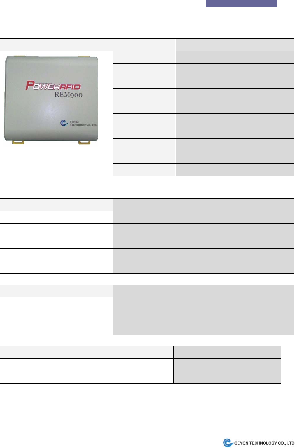
1. REM900 Feature
1.1 Product Feature
REM900 Parameter Description
Frequency 860MHz ~960MHz (Optional)
RF Output Power 30dBm Max
Attenuation 0.5dB 32step
Antenna Channel 4EA(Option : Channel Selectable)
Antenna connector SMA female
DC Power Supply DC 9V 3A
Communication TCP/IP, RS-232C
LED display POWER, ACTIVE
Dimensions (W)220mm * (D)223mm * (H)65mm
Weight 1.8Kg
1.2 Environmental Feature
Item Feature
Operating Temp. Range -10℃ to +60℃ (with proper ventilation)
Operating Humidity Range 10 % to 90 % (non condensing)
Operating Atmosphere Range 1 atm. (atmosphere)
Keeping Temp. Range -20℃ to +70℃
Keeping Humidity Range 10 % to 90 % (non condensing)
1.3 Antenna Feature
Type Gain(Max)
FSC-06(SMA Female connector) 4.5dBi
FSDC-07(SMA Female connector) 4.5dBi
FDC-08(N Female connector) 6dBi
1.4 Cable Feature
Type Loss(Max)
SMA(male)-LMR200(Length:10(max)) cable-SMA(male) 3.5dB
N(male)-LMR200(Length:10(max)) cable-N(male) 3.5dB

4
Ceyon RFID 900
2. REM900 Configuration
2.1 Power and LED Indicator
- PWR : Power On Indicator
- ACT : Tag Reading Indicator
2.2 Antenna Connector
Use TX/RX/0 to TX/RX3 connector for TX/RX common antenna.
RX0 to RX3 are reserved for RX only ports. In case of TX/RX separate antenna configuration, RX0 to RX3
are used for RX port and TX/RX/0 to TX/RX3 are for TX port.
2.3 TCP/IP LAN Connector
Supports 10Base-T LAN.
2.4 RS-232C Connector
Serial interface to the Host(Optional).
2.5 USB Connector
Used only for program download.
2.6 DC Pwer Suppply Jack
Use 9V 3A DC adapter provided with REM900.
** Caution : Use of other vendor’s adapter may cause product’s malfunction or performance degradation.
3. REM900 Installation
Check if there is any RF interference which may cause product’s performance degradation.
Refer to software user’s guide for software installation.
3.1 Power supply
- Be sure to use qualified DC9V 3A adapter provided by product supplier.
- Check if PWR LED indicator is lit right after plugging DC adapter into REM900.
3.2 Antenna Connection
- Use TX/RX/0 to TX/RX3 connector for single channel antenna.
- RX0 to RX3 are used for RX only ports. In case of TX/RX Dual channel antenna configuration,
5
Ceyon RFID 900
RX0 to RX3 are used for RX port and TX/RX/0 to TX/RX3 are for TX port.
- Contact supplier for Single or Dual antenna configuration.
- Antenna and Tag performance affects total Product performance.
- Provided antenna’s parameters are typically: 6dBic circular polarity
- Default antenna configuration is to use TX/RX3 for single channel antenna.
- Antenna is activated one at a time. Antenna ports to be activated is selectable and sequence is also
programmable.
3.3 Communication Line Connection
REM900 supports one communication channel either 10Base-T TCP/IP or DB-9 RS-232C.
Contact supplier to make sure of communication channel.
It is recommendable to make the the dedicated cable for it provided by us. And if not, prepare
another one referring to the wiring diagram.
3.3.1 RS-232C
- Be sure to use proper RS-232C connector cable.
- Provided DSUB-9P RS-232C cable is 1 : 1 straight connection type for Host PC connection.
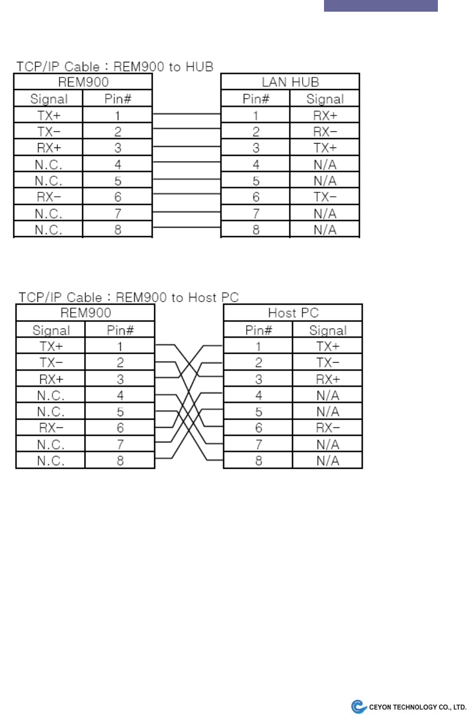
3.3.2 TCP/IP
- Be sure to use proper TCP/IP connector cable.
- Provided TCP/IP cable is 1 : 1 straight connection type for LAN Hub connection. Use Cross cable
refering to following chapter for direct connection to Host without Hub.
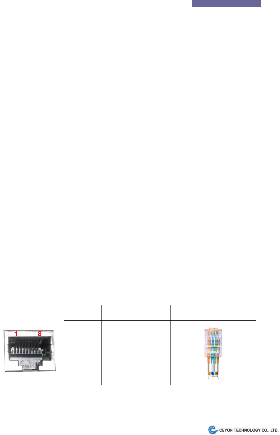
3.3.3 TCP/IP connector pin connection diagram
The picture below shows the connection table on TCP/IP cable Interface.
Pin number Signal abbreviation Cable Interface
1
2
3
4 ~5
6
7 ~ 8
TX+
TX-
RX+
None
RX-
None
The pin connection diagram of RJ45(TCP/IP) connector is shown below.
6
Ceyon RFID 900
Provided RJ45 connector cable is to connect to HUB.
If you want to connect REM900 with Host PC, cross cable is required.
4. Problem and Solution
Please refer to typical trouble shooting and frequent Q&A for your convenience.
If you still feel difficulty please contact supplier.
4.1 Turn on failure
Q1. Power Indicator doesn’t light on power source connection.
A1. Follow the step below.
- Check DC power output from adapter plug. (DC9V 3A)
- Unplug and reconnect the DC power source of the unit, REM900 after 10 seconds.
- Observe if PWR LED turns on right after power on. Then see if ACT LED turns on for a second 10 seconds

7
Ceyon RFID 900
after PWR turns on.
4.2 Communication failure
Q1. The RS-232C connection between Host and REM900 has failed.
A1. Follow the step below.
- Check if straight RS-232C cable is used.
- Check if communication configuration such RS-232C Baudrate is correct.
- Check if the connection is tight enough.
- Check REM900 LED operation is OK..
Q2. The TCP/IP connection has failed.
A2. Follow the step below.
- Check if proper TCP/IP cable is used. Refer to above chapter for detail.
- Check if communication configuration such as TCP/IP addess is correct.
- Check if the connection is tight enough.
- Check REM900 LED operation is OK..
4.3 Operation failure
Q1. REM900 does not read Tags
A1. Tag
- Check if the Tag to read is ISO/IEC18000-6C or EPC GEN2 type.
A2. Antenna
- Check if antenna is connected properly.
- Check if selected antenna port is activated.
A3. Communication
- Check if communication is OK.
Q2. Tag reading is to slow or unstable.
A1. Environment
- Check if other UHF RFID readers are operating nearby. They will interfere each other and degrade
performance.
- Metal structure located between antenna and tag may interfere the RF signal.
A2. Tag
- Try another ISO/IEC18000-6C type tag.

8
Ceyon RFID 900
A3. Antenna
- Check if antenna connection is tight enough.
- Check if selected antenna port is activated.
Note: To use this device , professional installation must be applied
If the problem hasn’t been solved with the action above, contact Ceyon Technolgy co., LTD.
www.ceyon.co.kr (82-2-3418-3030)
Regulatory Statements to be included in the Users Guide for Sputnik
USA-Federal Communications Commission (FCC)
This device complies with part 15 of the FCC Rules. Operation is subject to the following
two conditions: (1) This device may not cause harmful interference, and (2) this device
must accept any interference received, including interference that may cause undesired
operation.
This equipment has been tested and found to comply with the limits for a Class B digital
device, pursuant to Part 15 of FCC Rules. These limits are designed to provide reasonable
protection against harmful interference in a residential installation. This equipment
generates, uses, and can radiate radio frequency energy. If not installed and used in
accordance with the instructions, it may cause harmful interference to radio
communications. However, there is no guarantee that interference will not occur in a
particular installation.
If this equipment does cause harmful interference to radio or television reception, which
can be determined by tuning the equipment off and on, the user is encouraged to try and
correct the interference by one or more of the following measures:
-Reorient or relocate the receiving antenna
-Increase the distance between the equipment and the receiver.
-Connect the equipment to outlet on a circuit different from that to which the receiver is
connected.
-Consult the dealer or an experienced radio/TV technician for help.
Any changes or modifications not expressly approved by the party responsible for
compliance could void the user’s authority to operate the equipment.
Caution: Exposure to Radio Frequency Radiation.
To comply with FCC RF exposure compliance requirements, for mobile configurations, a
separation distance of at least 20 cm must be maintained between the antenna of this device and
all persons.
This device must not be co-located or operating in conjunction with any other antenna or
transmitter.