Cfm Corporation 7000 Users Manual
7000 to the manual 42c3eda7-cfbf-42de-b998-edde03a0c433
2015-02-05
: Cfm-Corporation Cfm-Corporation-7000-Users-Manual-529562 cfm-corporation-7000-users-manual-529562 cfm-corporation pdf
Open the PDF directly: View PDF ![]() .
.
Page Count: 29
O w n e r ’s M a n u a l and A s s e m b l y G u i d e
FOR YOUR SAFETY
If you smell gas:
1Shut o gas to the appliance.
2Extinguish any open ame.
3Open lid.
4If odor continues, immediately call
your gas supplier or re department.
FOR YOUR SAFETY
1Do not store or use gasoline or other
ammable vapors and liquids in the vi -
cinity of this or any other appliance.
2An unconnected liquid propane cylin -
der should not be stored in the vicinity
of this or any other appliance.
AO000102-901
Model 7000
Series
Portable Gas
Barbecue Grill
ASSEMBLER / INSTALLER:
Leave these instructions with the consumer
CONSUMER / USER:
Read all of these instructions, and keep them in a safe place for future reference.
Table of Contents Page Number
Chapter One - INSTALLATION 3
Choosing a Safe Location 4
Portable L.P. Gas Grills 5 - 6
L.P. Gas Dealer Instructions 7
Chapter Two - ASSEMBLY 8
Step 1 ( Identify Parts ) 9
Step 2 ( Assemble Pillar to Base ) 10 - 11
Step 3 ( Attach Grill Bottom ) 12 - 13
Step 4 ( Assemble Grill Lid ) 14 - 15
Step 5 (Side Tables ) 16
Step 6 ( Rock Grate and Briquettes ) 17
Step 7 ( Cooking Grids ) 18
Installing an L.P. Gas Cylinder 19
Connecting an L.P. Gas Cylinder 20
Connecting to Natural Gas (Model 7000N only) 21 - 22
CFM Corporation
2695 Meadowvale Boulevard
Mississauga, Ontario L5N 8A3 Canada
(800) 668-5323
www.cfmcorp.com
Service Note: If you are experiencing difficulties or are dissatisfied with your purchase, please contact CFM at
the telephone number listed above prior to returning your grill to the store.
®
Formerly:
Now:
Installation Chapter 1
3
The L.P. Gas Fuel Supply System
Correct Filling and Handling of the
L.P. Gas Fuel Cylinder
Important Information Necessary
to Safely Use a Gas Grill.
Series 7000 Models
The gas fuel used by this product is
highly flammable and must be used in
a responsible and cautious manner.
It is your responsibility to assemble,
operate, and maintain your gas
barbecue grill properly.
If these instructions are ignored, there
is a possibility of a hazardous fire or
explosion which could result in proper-
ty damage, physical injury or death.
1. The gas barbecue grill may only be
used for cooking out-of-doors.
•Do not operate this barbecue in garages,
breezeways, sheds or any enclosed area.
• Operating this or any gas-fired appliance in
an enclosed area can produce a build-up of
carbon-monoxide, which could result in injury
or death.
2. Installation must conform with local
codes or, in the absence of local codes,
with either the National Fuel Gas Code,
ANSI Z223.1, NFPA 54 (USA), or
CAN/CGA-B 149.2, Propane Installation
Code (Canada) and CAN/CGA-B 149.1
Natural Gas Installation Code.
To check local codes, contact your local gas
dealer or gas company listed in the Yellow
Pages for recommended installation proce-
dures and regulations.
3. This appliance is not intended to be
installed in or on a recreational vehicle
and/or boat.
4. Keep the barbecue grill at least 24 inch-
es (61 cm) away from any combustible con-
struction.
•Do not use a grill under a ceiling or cover
where the heat or flame could cause damage.
• Choose a level surface where the grill is not
facing directly into the wind.
• Avoid moving the grill during use.
5. The grill area must be clear and free
from combustible materials, gasoline, and
any other flammable liquids or vapors.
•Do not use lighter fluid or charcoal briquettes
in a gas grill. The flow of combustion and venti-
lation air is not to be obstructed. The ventilation
openings of the cylinder enclosure must be kept
free and clear from other debris.
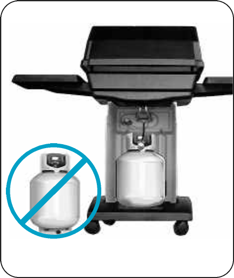
6. Do Not store a spare L.P. gas cylinder
under or near this appliance.
7. NOT FOR USE BY CHILDREN.
Keep children and pets away from hot grill.
•Place your barbecue grill in a location away
from children and pets.
• Do not leave grill unattended when in use.
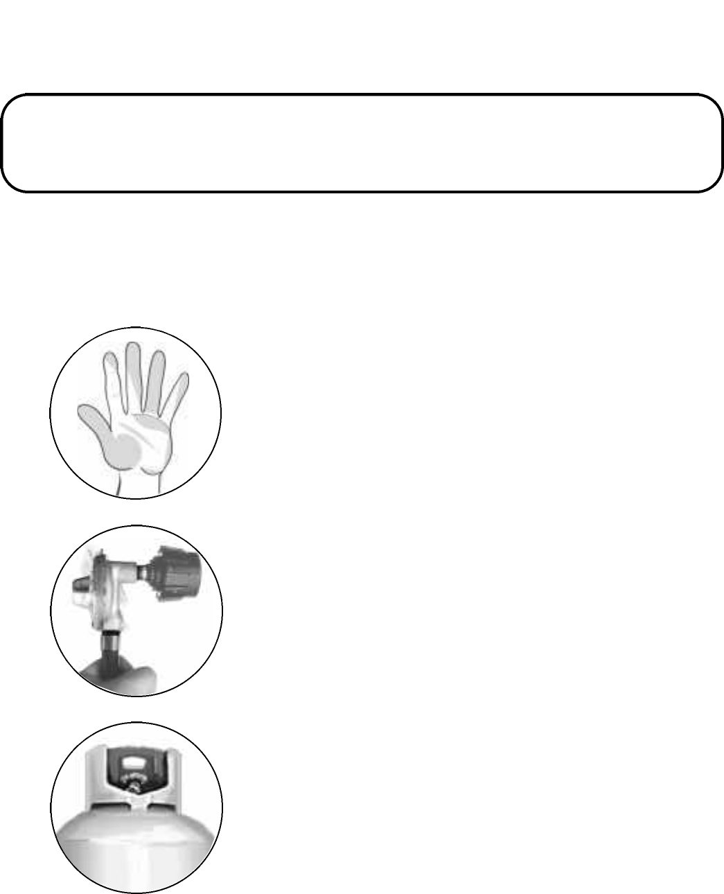
8. The outside of the barbecue grill will
become hot during use.
• To avoid burns, do not touch any hot grill sur-
face. If necessary, use a protective glove when
operating control knobs, tank shut-off valve, or lid
handle.
•Do not place combustible material, such as
cloth or plastic, on grill surface during use.
• Do not lean on side tables or place more than
15 pounds of weight on a side table.
9. Make sure that the heat shield and drip
pan are in place under the grill bottom.
•Heat and hot drippings from cooking food
could damage the fuel supply system.
Choosing a Safe Location for a Gas Barbecue Grill.
4
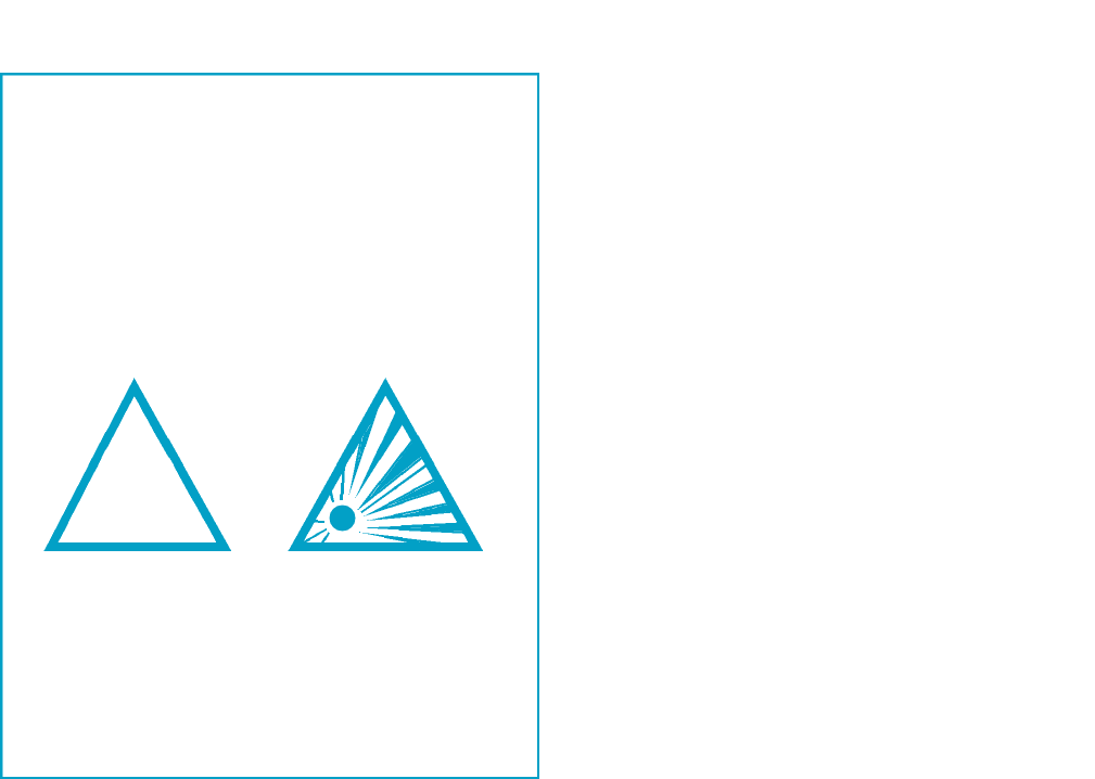
!
FUEL REGULATOR AND HOSE
The fuel regulator supplied is equipped with a
Type 1 coupling nut. Do not attempt to connect
to any other L.P cylinder not equipped with a
mating Type 1 cylinder valve. This grill is not to
be used with any other cylinder connection
device.
The fuel regulator and hose assembly with the
Type 1 fitting supplied must be used with the
appliance. Do not use a hose and regulator
assembly other than the one supplied with the
grill or a manufacturer’s replacement fuel pres-
sure regulator assembly.
The Type 1 connection system has the follow-
ing features:
1. The system will not allow gas to flow until a
positive connection has been made.
2. The system has a thermal element that will
shut off the flow of gas between 240° F and
300° F.
3. The system has a flow-limiting device which
when activated, will limit the flow of gas to 10
cubic feet per hour.
4. The pressure regulator and hose assembly
provided is factory set at an outlet pressure of
11 inches water column (.4 lb. per sq. inch).
WARNING: Any attempt to adjust the regu-
lator is dangerous and could create a situa-
tion causing personal injury or property
damage. Consult your L.P. gas dealer if you
think the regulator is not working properly.
FUEL-CYLINDER SPECIFICATIONS
Any L.P. gas-supply cylinder used with this grill
must be approximately 12 inches diameter and
18 inches high. The maximum fuel capacity
must be 20 pounds of propane. Full-cylinder
weight should be approximately 38 pounds (43.7
lbs. nominal water capacity).
The L.P. cylinder must have a shut-off valve
terminating in a Type 1 L.P gas-cylinder-valve
outlet. A Type 1 compatible cylinder with a Type
1 cylinder valve has a positive seating connec-
tion that does not permit gas flow until a positive
seal has been obtained.
Portable L. P. Gas Barbecue Grills
5
WARNING: Do not use natural gas in an
appliance designed for L.P. gas. Use only liquid
propane (L.P.) gas in an appliance designed for
L.P. gas.
L.P. Gas
Liquid Propane (abbreviated L.P.) gas is
stored under high pressure inside a cylinder and
vaporizes when released. It is important that
there are no leaky connections on the grill’s fuel
supply system.
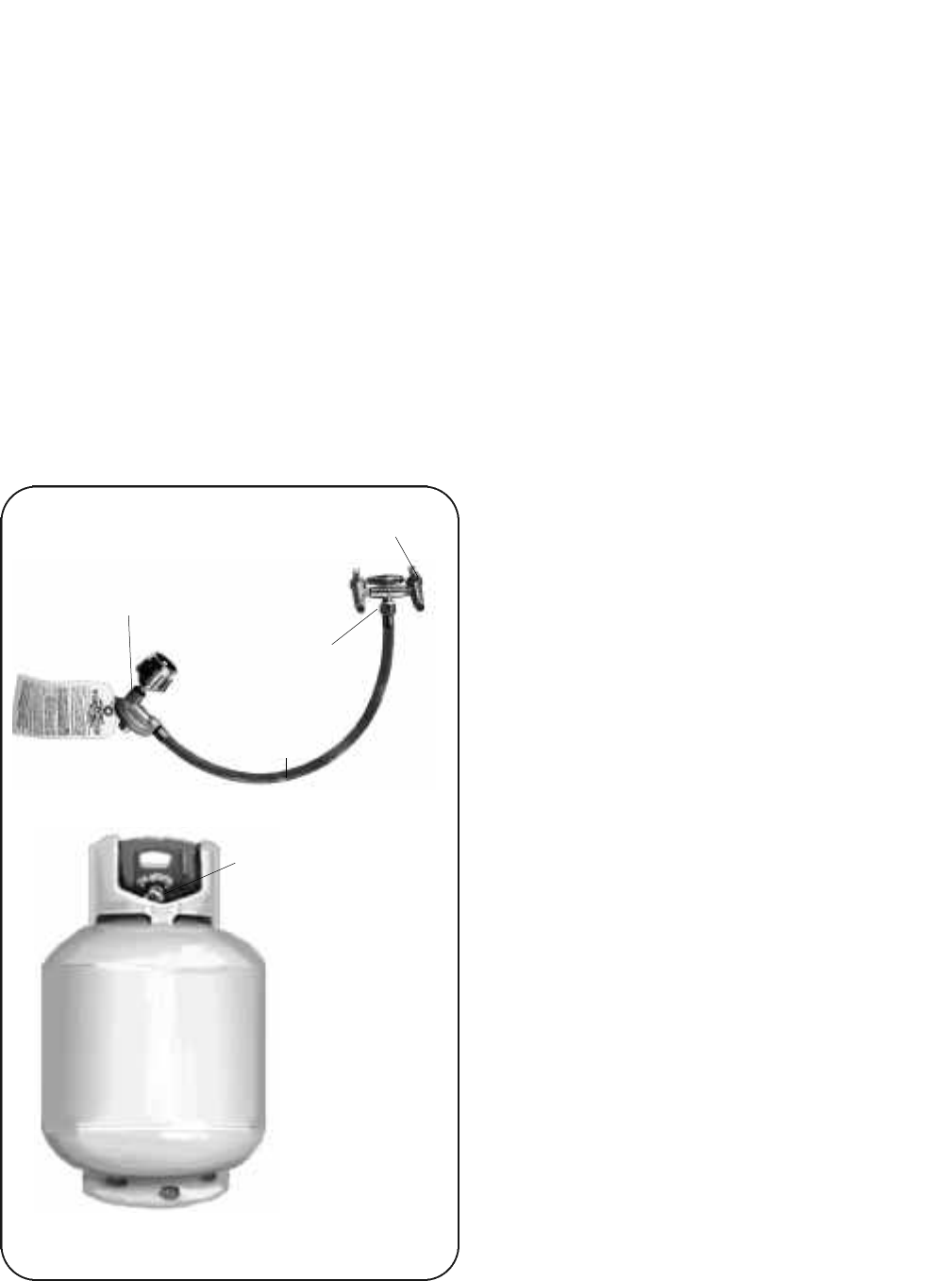
The L.P. FUEL SUPPLY SYSTEM
An L.P. gas grill requires a fuel delivery sys-
tem made up of an L.P gas supply cylinder, a
fuel regulator with hose and a gas-control valve.
L.P. Gas
Cylinder
Type 1 Fuel Regulator
Dual Burner Fuel-Control Valve
Cylinder Control
Valve
Fuel Supply
Hose
Valve Orifice
The L.P. Fuel Supply System
DANGER: Do not insert any foreign objects
into the valve outlet. You may damage the
back check. A damaged back check can
cause a leak, which could result in explo-
sion, fire, severe personal injury, or death.
The cylinder must be arranged for vapor with-
drawal. It must also include a Collar to protect
the cylinder valve. A safety-reIief device having
direct communication with the vapor space of
cylinder must be provided. This will expel high-
pressure gas if the cylinder is overfilled or over-
heated.
All L.P. gas cylinders used with this appliance
shall be constructed and marked in accordance
with the specifications for L.P. gas cylinders of
the U.S. Department of Transportation (DOT) or
the National Standard of Canada, CAN/CSA-
B339, Cylinders, Spheres and Tubes for
Transportation of Dangerous Goods; and
Commission, as applicable; and shall be provid-
ed with a listed overfilling-prevention device.
Read labels on the L.P. gas-supply cylinder.
The cylinder provided is shipped empty for
safety. Allow only a qualified L.P. gas dealer to
fill or repair your L.P. gas-supply cylinder.
Inform the gas dealer if it is a new or used cyl-
inder to be filled. Caution the gas dealer not to
overfill the fuel cylinder.
After filling, have the gas dealer check for
leaks and to check that the relief valve remains
free to function.
Have the gas dealer weigh cylinder after filling
to ensure that the cylinder is not overfilled.
DANGER:
a.) Do not store a spare L.P. gas cylinder
under or near this appliance.
b.) Never fill the gas cylinder beyond 80
percent full.
c.) If the information in “(a.)” and “(b.)” is
not followed exactly, a fire causing death or
serious injury may occur.
Portable L. P. Gas Barbecue Grills
TRANSPORTING A FULL CYLINDER
WARNING! Handle a full cylinder with care.
Gas is under high pressure.
You should transport only one cylinder at a
time. Transport the cylinder in an upright and
secure manner with control valve turned off and
the POL plug in place.
Do not transport cylinder in the passenger
compartment of a vehicle.
Do not leave cylinder in direct sunlight or in a
high-heat area such as a closed car trunk.
High-heat areas could cause the relief valve to
vent gas.
Do not store cylinder in a building, garage or
any other enclosed area. Store outdoors in a
well ventilated area, away from people and out
of the reach of children.
Use a cylinder cap on cylinder-valve outlet
during transport and when the cylinder is not
connected to grill. Keep cylinder valve closed
when not in use.
6
Do not store spare cylinders near grill.
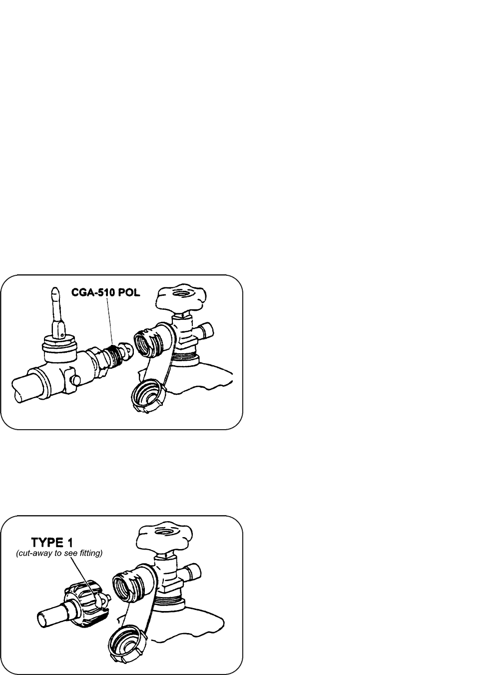
Filling a Type 1 Cylinder Valve
Example A: shows a CGA-510 POL fitting.
Example B: shows using a Type 1 POL fitting.
When using a cylinder exchange, be sure the
exchanged cylinder is a Type 1 cylinder; a 510
POL cylinder will not fit a Type 1 regulator.
FILLING AND PURGING TYPE 1 L.P. GAS CYLINDERS
DANGER! Purging and filling of L.P. Gas
cylinders must be performed by personnel
who have been thoroughly trained in accept-
ed L.P. gas industry procedures. Failure to
follow this instruction may result in explo-
sion, fire, severe personal injury, or death.
IMPORTANT: Purge new cylinders before fill-
ing. This tank is easily filled with a standard
CGA 510 POL filling connection.
The L.P. gas cylinder has a Type 1 cylinder
valve with a back-check module in its outlet that
will not permit gas to flow until an evacuation
device is installed. To purge the L.P. gas cylin-
der, the back-check module must be opened
with an evacuation device.
PURGING AND EVACUATION DEVICES FOR L.P. GAS
CYLINDER WITH TYPE 1 CYLINDER VALVES
A. Hose-end valve with a bleed port: Purging
can be accomplished using a hose-end valve
containing a bleed port, which also allows for
evacuation without the use of an adapter.
B. Hose-end valve without a bleed port: When
a hose end valve does not have a bleed port, a
separate device must be used for evacuation.
C. Purging using a Type 1 connection: L.P.
gas cylinder evacuation can be accomplished
during each purging by using a Type 1 connec-
tion. The Type 1 valve outlet has an 1 5/16"
external ACME right-hand thread that will
accept this connection.
CAUTION: After purging or filling an L.P. gas
cylinder, do not insert a POL plug into the valve
outlet. Insertion of this plug will prevent the
back-check from closing. Use ONLY the provid-
ed cap and strap attached to the outlet. Close
the cylinder valve knob before returning the
cylinder to the customer.
For proper purging procedures in the U.S.A.
refer to: Safety Bulletin NPGA #133, “Purging
L.P. Gas Cylinders,” and Safety Bulletin NPGA
#130, “Recommended Procedures for Filling
Cylinders.”
DANGER: Do not fill an L.P. gas cylinder
beyond 80% full. If this information is not
followed exactly, a fire causing serious
injury or death may occur.
7
Example A
Example B
Take These Instructions to the L.P. Gas Dealer.
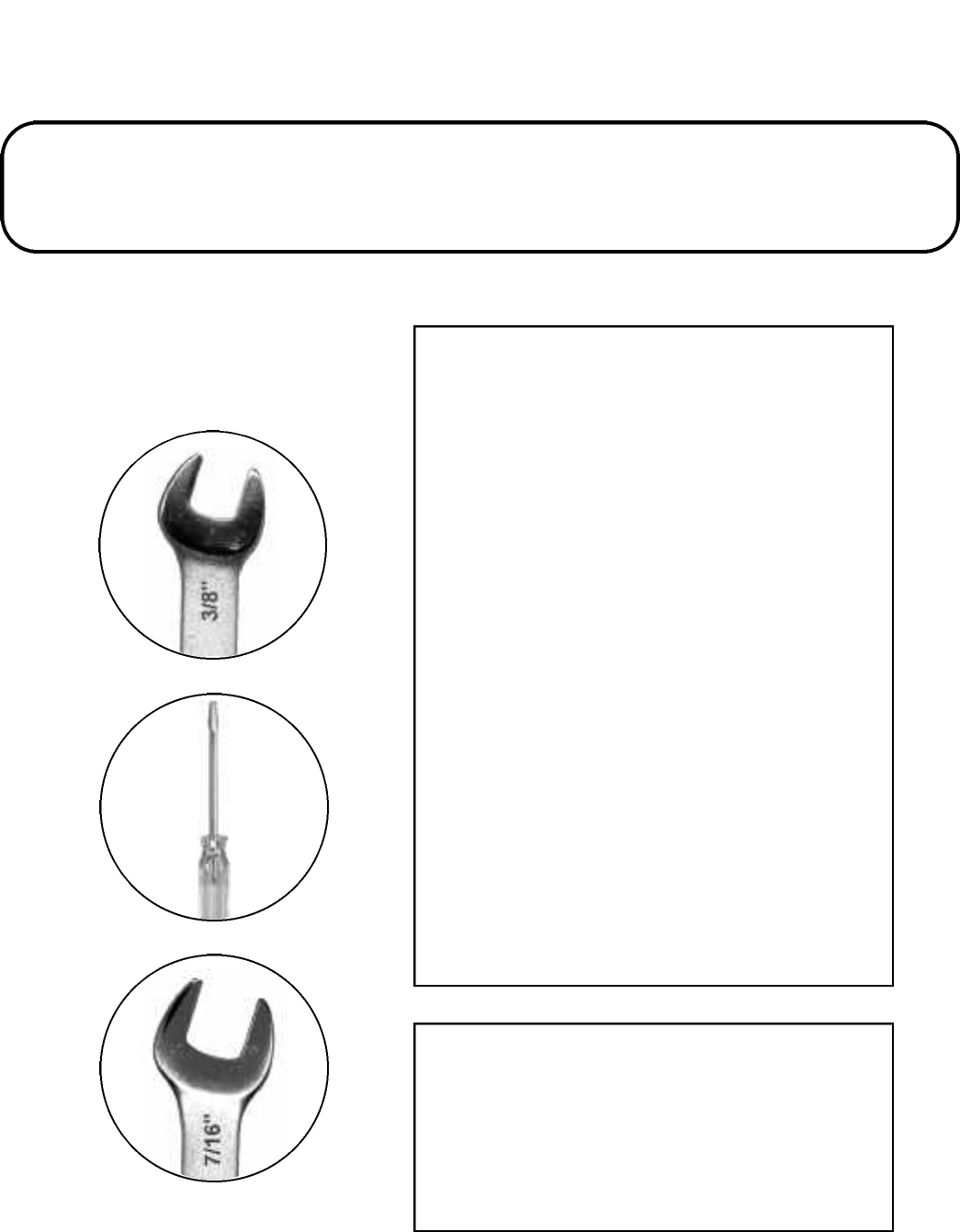
Assembly Instructions Chapter 2
Tools needed to assemble grill:
• 3/8” open-end wrench*
• flat blade screwdriver
• 7/16” open-end wrench*
*HINT: A socket set or an adjustable
wrench may be used instead.
Getting Started
1. Please follow the steps in the order that
they are presented.
2. Assemble the grill where you plan to use it.
3. You may want to place an old towel or cloth
at the assembly site to prevent scratches to
your deck and/or to prevent nuts and bolts from
becoming lost.
4. Have a friend help. Your barbecue grill is
made of an aluminum body. An assistant can
make the assembly easier by holding the parts
in place while you fasten the nuts and bolts.
Liquid Propane Models
L.P. gas grills are provided with an L.P. gas
supply cylinder, shipped empty for safety rea-
sons. To be ready to grill immediately, please
have the fuel cylinder filled with L.P. gas by an
authorized L.P. gas dealer.
Model 7000N
Natural gas grills require a connection to nat-
ural gas-supply. The gas connections should be
made only by a qualified installer or a licensed
plumber. The gas-supply line must not be
installed by the consumer.
8
Series 7000 Models
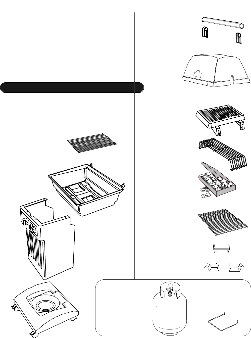
cooking grid
(2)
grill bottom
(1)
handle standoff ( 2 )
handle ( 1 )
rock grate
( 1 )
ceramic briquettes
( 1 package )
warming rack
( 1 )
L.P. gas
cylinder
( 1 )
cylinder
retainer
wire ( 1 )
heat shield
( 1 )
grease pan
( 1 )
side tables
( 2 )
Unpack grill parts.
1. Remove and set aside all inner boxes and
parts from the master carton.
2. Remove and set aside all wrapping paper
and additional packaging from the parts.
3. Do not destroy carton or packing until your
grill is completely assembled and operating
to your satisfaction.
Identifying the Grill Parts • Assembly Step 1
Locate these parts:
9
Model
7000
(LP Gas
Grills only)
pillar
( 1 )
base
( 1 )
Main bag containg:
( 1 ) hardware bag “A”,
( 1 ) hardware bag “B”,
( 1 ) hardware bag “C”,
( 1 ) hardware bag “D”
grill lid
( 1 )
Locate these parts:
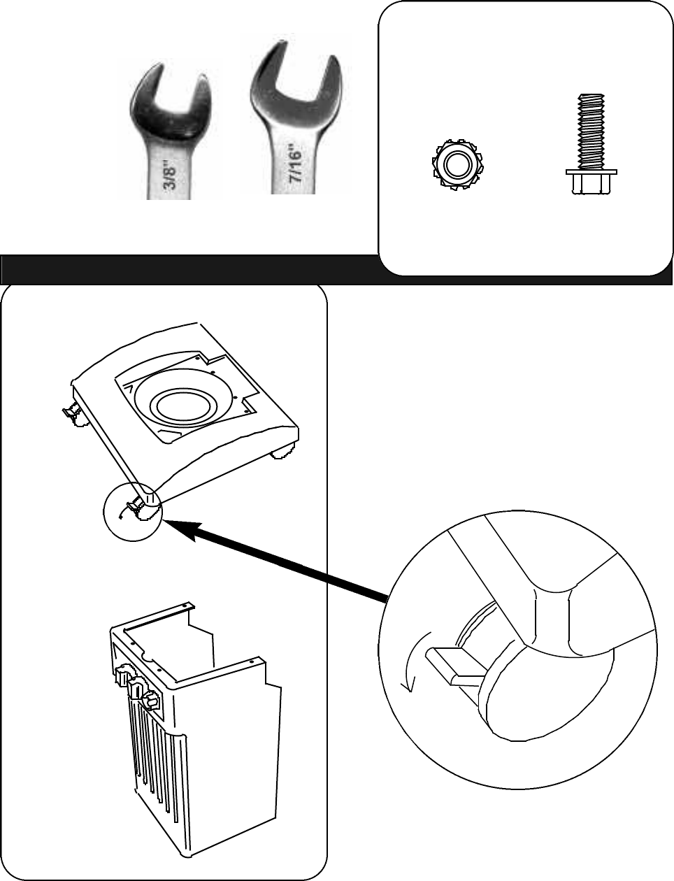
tools needed:
3/8” open-end wrench
7/16” open-end wrench
base
( 1 )
Assembly Step 2 • Assemble the Pillar to Base.
10
pillar
( 1 )
1. Lock the preassembled casters
on base by pushing down on the
latch.
1/4-20 x 3/4”
( 4 )
1/4-20
( 4 )
Use hardware bag “A”:
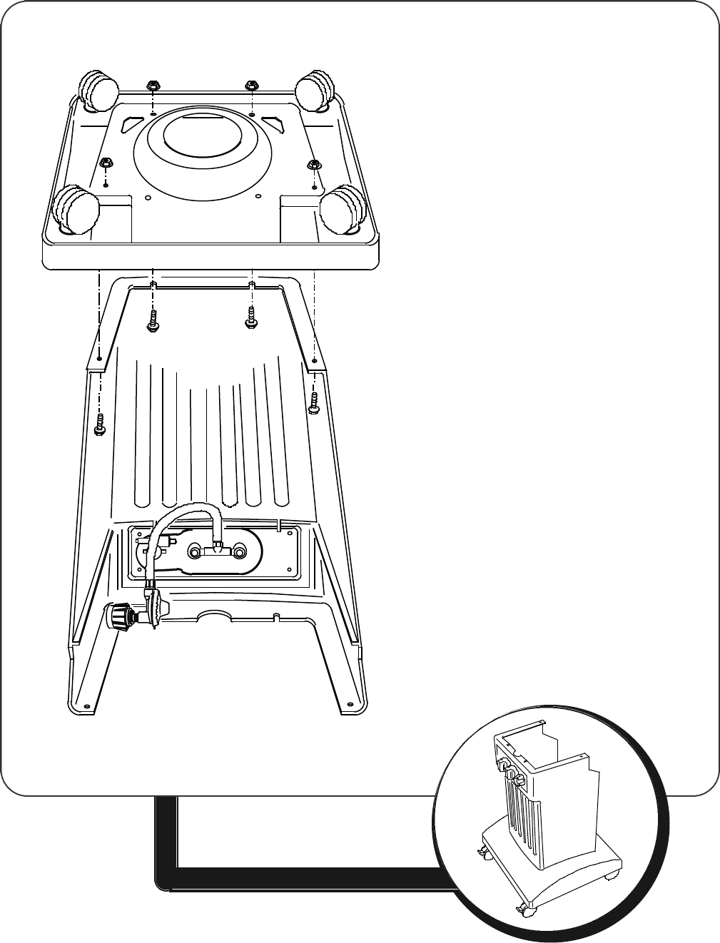
11
2. Position the pillar upside down,
and set the base onto the pillar
as shown.
Working from the open side of pillar:
3. Insert four bolts through the holes
in the pillar and through the four
holes in the base. Thread nuts
onto bolts. Align rear holes and
insert bolts. Add nuts and use
wrenches to tighten.
4. Carefully turn the assembly
upright.
5. Check the preassembled control
valve located inside the pillar.
Remove the plastic film covering
the front of the control panel
plate.
Your grill will now look like this >
Locate these parts:
tools needed:
3⁄8" open-end wrench
7⁄16" open-end wrench
12
1. Place the heat shield on the pillar,
aligning holes as shown.
2. Position the grill bottom onto the pillar
so that the rear hinge struts are toward
the open side of the pillar, as shown.
3. Four holes in the grill bottom will align
with the four holes in the heat shield
and the pillar.
hinge strut
back
Assembly Step 3 • Attach the Grill Bottom.
grill bottom
( 1 )
1/4-20 x 1”
( 4 )
1/4-20
( 4 )
Use hardware bag “B”:
heat shield
( 1 )
heat
shield
13
Your grill will now look like this >
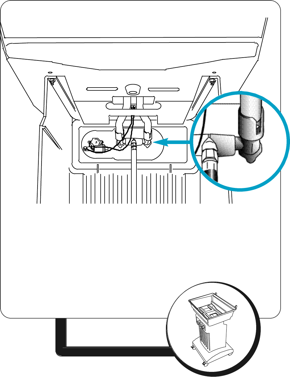
4. IMPORTANT:
Make sure the control-valve ends are
inside the burner tubes extending
through the grill bottom. (See detail).
5. Insert four bolts into matching holes in
the grill bottom and secure with nuts.
6. Locate the two black lead wires
beneath the grill bottom. Press the
loose ends of the lead wires onto the
metal tabs located on the back of the
igniter unit.
Grill bottom as shown from below back.
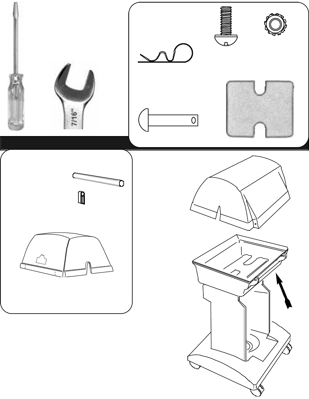
Locate these parts:
14
Assembly Step 4 • Assemble the Grill Lid
tools needed:
7/16" open-end wrench
flat-blade screwdriver
handle standoff
( 2 )
handle
( 1 )
1. Position the back of the lid so that the rear
holes are in line with the hinge struts on
the back of the grill bottom.
2. Gently set the grill lid onto the grill bottom.
hairpin
( 2 )
use
hardware bag “D”:
1/4-20 x 5/8”
bolt ( 4 )
standoff gasket
( 2 )
1/4-20
hex nut ( 2 )
hinge pin
1/4 x 1 1/8”
( 2 )
grill lid
( 1 )
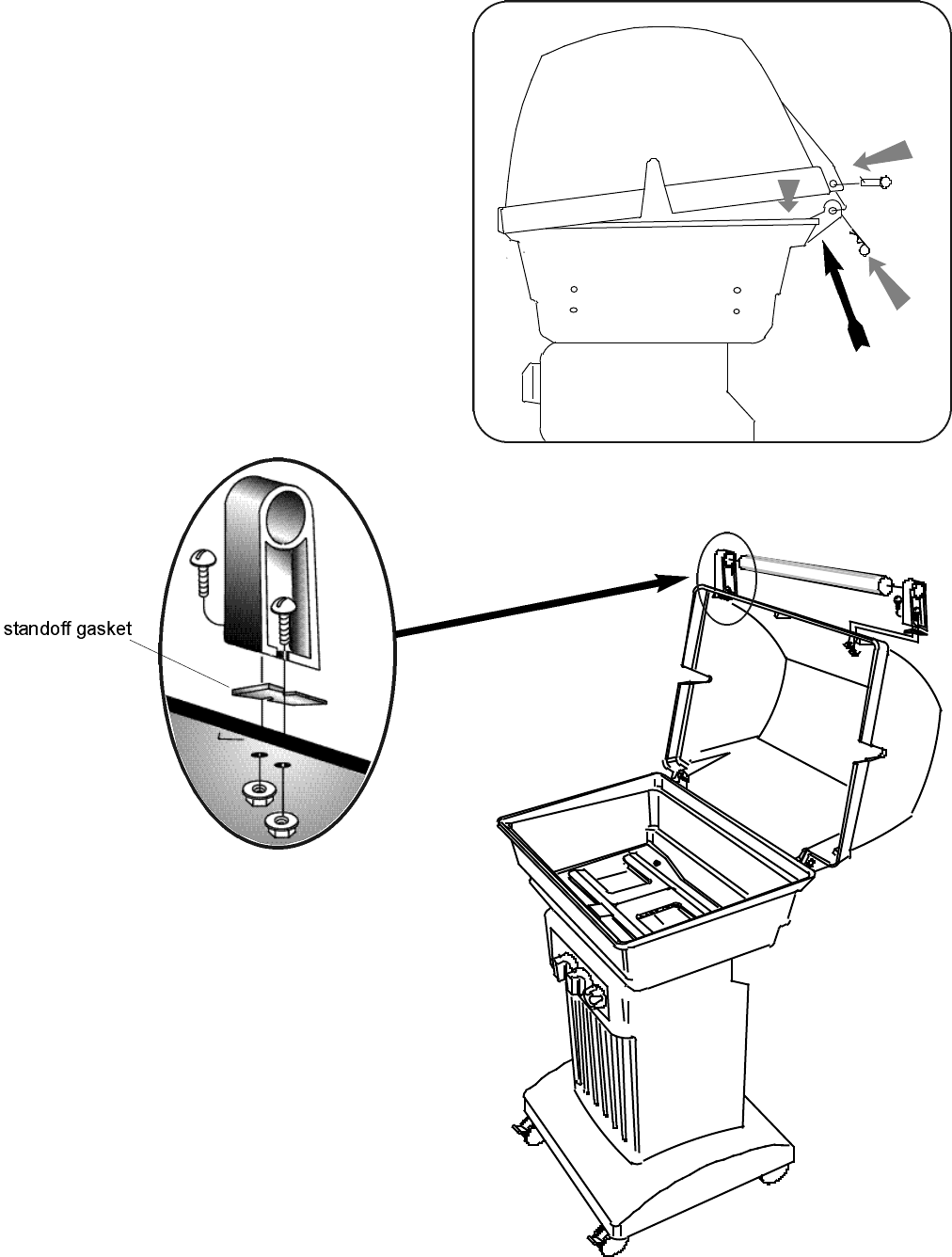
7. Raise the lid to attach the front handle.
8. Attach a handle standoff to the front of
the grill lid, as shown.
9. Insert one end of the handle into the
hole of the standoff.
10.Place other standoff onto handle and
while holding the handle in place
assemble the opposite standoff to the
lid in the same manner.
3. Hold the lid to align the hinge holes.
4. Insert a hinge pin through the hinge
hole in the lid and into the hole in the
bottom hinge strut.
5. After the hinge pin is in place, insert a
hair pin through the hole of the hinge
pin to secure it.
HINT: There is an air space between
the back of the lid and the grill bottom
where you can install the pins.
6. Repeat for the opposite side.
4.
3.
5.
15
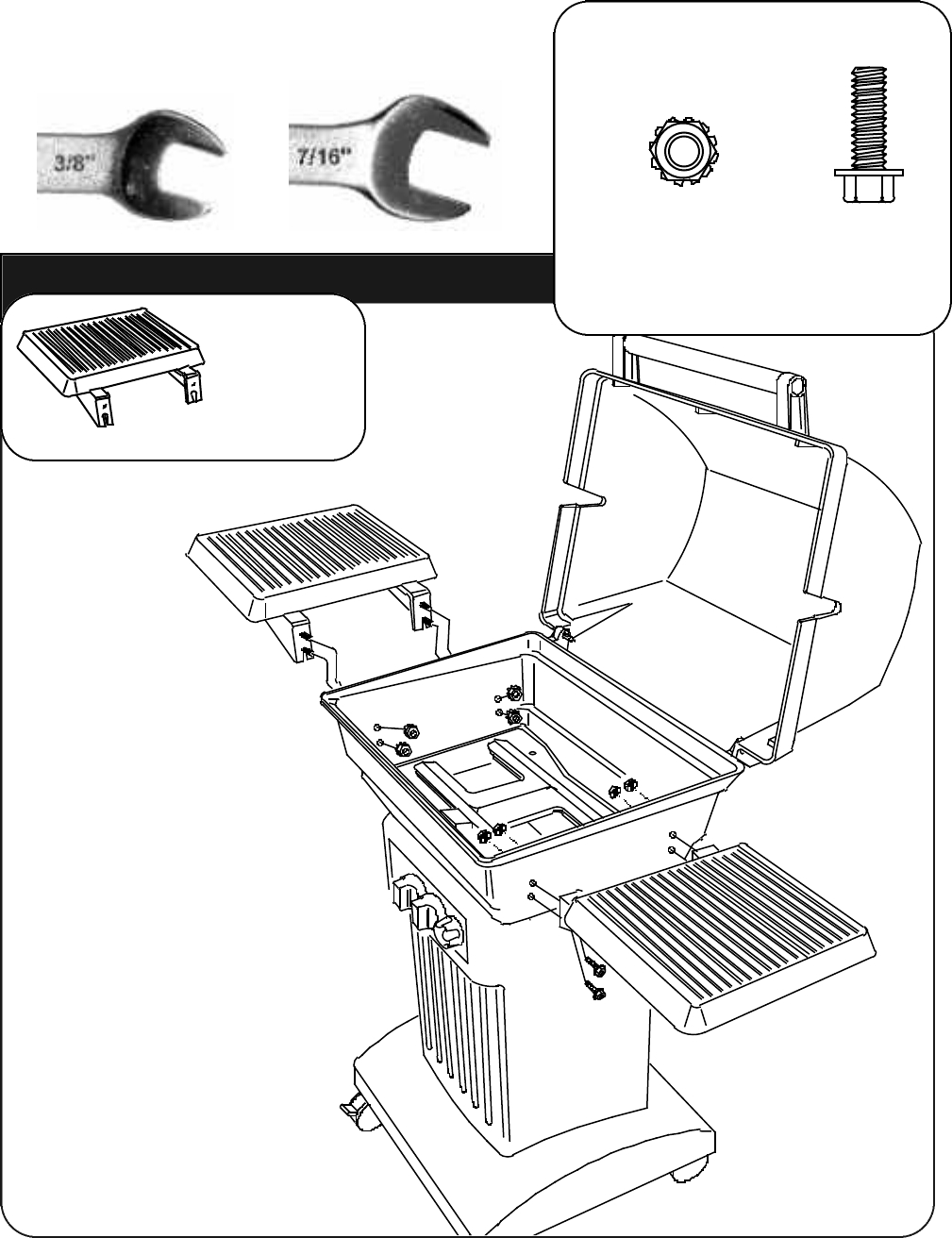
Locate these parts:
16
Assembly Step 5 • Attach the Side Tables to the Grill.
1. Insert 3/4" bolts through
holes in the support arms
of the side tables.
2. Attach each side table to
the four holes located in
the side of the grill bottom
using the locking hex nuts
provided.
NOTE: Model 7500 has one
RIGHT side table. Please
refer to Model 7500
Assembly Step SB1 on
page___ of this manual.
side table
( 2 )
Use hardware bag “C”:
1/4-20
hex nut
( 8 )
tools needed:
3/8" open-end wrench
7/16" open-end wrench
1/4-20 x 3/4”
bolt
( 8 )
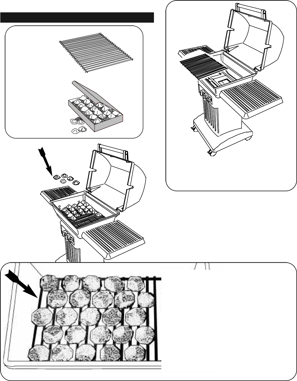
rock grate
( 1 )
ceramic
briquettes
( 1 box )
No tools are needed.
Assembly Step 6 • Install the Rock Grate and Briquettes.
17
1. Place the single rock grate into
the grill bottom.
3. It is important to properly arrange
the ceramic briquettes onto the
rock grate to allow for good air flow
during use.
NOTICE THE SPACING:
The proper amount of briquettes
are supplied and there is no need
to add more. Some space between
the briquettes is necessary.
2. Open the package containing
the ceramic briquettes and
place them on the rockgrate.
Locate these parts:
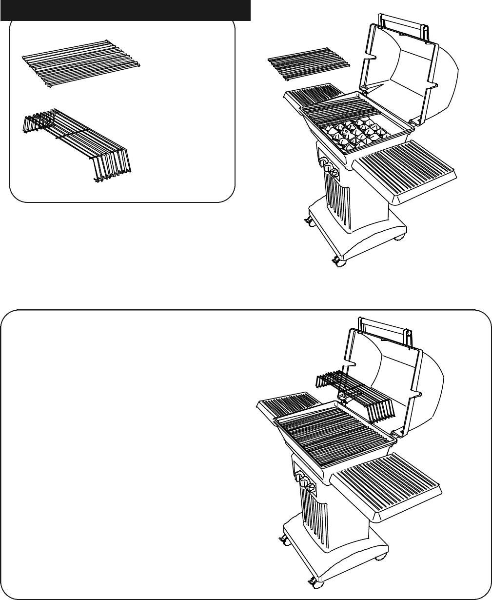
4. Set the two porcelain coated cooking
grids on the front and back ledges
formed inside the grill bottom for a
level cooking surface.
5. Set the warming rack onto the back
of the cooking grids.
Congratulations, your barbecue grill
is now assembled and ready to
connect to a fuel source.
18
No tools are needed.
Assembly Step 7 • Install the Cooking Grids.
cooking
grids
( 2 )
Locate these parts:
warming
rack
( 1 )
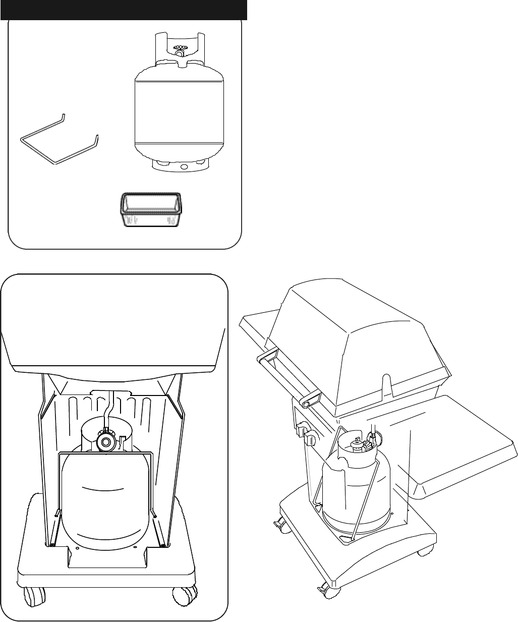
Locate these parts:
1. Working from behind the grill, set the
cylinder into the large round opening in
the grill base.
2. Position the cylinder-retainer wire around
the cylinder collar as shown.
3. Insert the left end of the wire into the
small opening in the base.
4. Flex the right side so that it fits into the
opposite opening on the right side of the
base.
Installing an L.P. Gas Cylinder.
no tools needed
cylinder
retainer
wire
( 1 )
19
WARNING: Connect the L.P. cylinder to
the grill outdoors only.
Fill the cylinder before connecting.
Read and follow all directions on the cylin-
der and fuel hose safety tags.
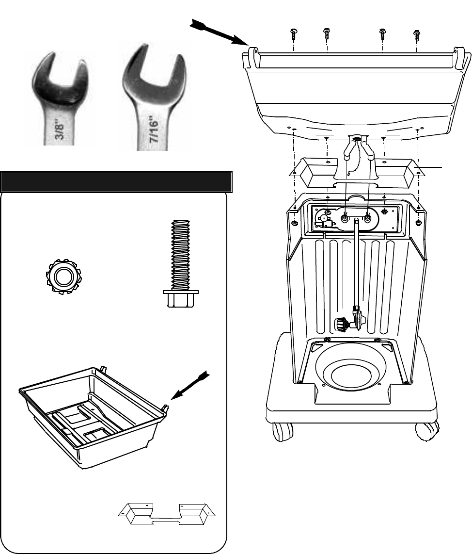
grease pan
( 1 )
L.P. gas
cylinder
( 1 )
1.
(To see this better, the grill is shown clear.)
2.
3.
4.
(Behind and below the grill bottom.)
complete the connection, do not use this valve
and regulator.
7. Make sure the hose has no kinks or sharp
bends and clears any areas that will become hot
during use. Never put strain on the hose where it
joins a fitting. The rubber fuel supply hose must
not touch the bottom grill casting during use.
8. Before lighting grill, check all connections for
leaks using a mild soapy-water solution.
9. Place an aluminum 3 1/2” x 6” loaf pan into
the opening in the heat shield located beneath
the grill bottom. During use the pan will catch hot
grease drippings that could damage the fuel sup-
ply system.
20
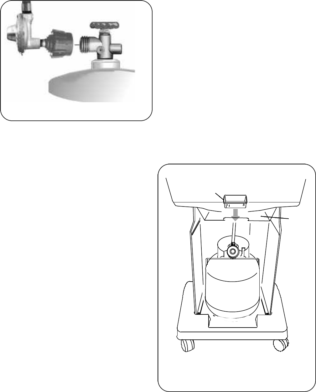
1. The top knob on the supply cylinder must
be closed. See that the top cylinder knob is
turned clockwise to a full stop.
2. Check that all the grill burner knobs are
turned off.
3. Remove the protective caps from the cyl-
inder valve and coupling nut, if present.
4. Hold the regulator in one hand and insert
the nipple into the valve outlet. Be sure the
nipple is centered in the valve outlet. The
coupling nut connects to the large outside
threads on the valve outlet. Use care not to
cross thread the connection.
5. Hand tighten the coupling nut clockwise
until it comes to a full stop.
Tighten by hand only. Do not use tools.
6. CAUTION: In the connection process, the
grill side of the connection will seal on the
back check in the valve, resulting in a slight
resistance. The connection requires about
one-half to three-quarters additional turn to
complete the connection.
NOTE: If you cannot complete the final con-
nection, disconnect the regulator and repeat
steps 4 through 6. If you are still unable to
Connecting the Regulator to Cylinder
Connecting an L.P. Gas Cylinder.
Install the Heat Shield and Drip Pan.
The grease pan is a 3 1/2”x 6” aluminum loaf
pan available at most grocery stores.
(Under the Grill Bottom.)
heat
shield
pan
DANGER: EXPLOSIVE AND FLAMMABLE!
If the appliance is for connection to
natural gas, the gas connections should
be made by a qualified installer or a
licensed plumber. The gas-supply line
must not be installed by the consumer.
The valve-orifices and fuel supply hose sys-
tem necessary for use with natural gas is differ-
ent than the system required for L.P. gas.
Modification to the burner valve/orifices allow
the use of natural gas. An L.P. cylinder is not
needed.
WARNING: Do not use liquid propane
(L.P.) gas in an appliance designed for nat-
ural gas. Use only natural gas in an appli-
ance designed for natural gas.
INSTALLATION FOR NATURAL GAS
The maximum inlet supply pressure is 11.0"
w.c. for propane gas and 7.0" w.c. for natural
gas.
The specified supply pressure is 11.0" w.c. for
propane gas and 7.0" wc. for natural gas.
The piping system should be installed by a
qualified service technician in accordance with
the National Fuel Gas Code (NFPA 54/ANSI
Z223.1) in the U.S.A., including:
1. The appliance and its individual shut-off
valve must be disconnected from the gas-sup-
ply piping system during any pressure testing
of that system at test pressures in excess of
1/2 psi (3.5 kPa).
2. The appliance must be isolated from the
gas-supply piping system by closing its individ-
ual manual shut-off valve during any pressure
testing of the gas supply piping system at test
pressures equal to or less than 1/2 psi (3.5
kPa).
Aquick-connect coupling sleeve with 3/8” female
end is provided. Install the connector socket at
the pipe end, after the shut-off valve. This must
be installed where the grill will be in use.
It is important to observe the safety guidelines
for choosing a safe location. The gas supply must
be shut off prior to installation of the quick con-
nector socket. Use only a matching factory
authorized quick-connect plug with the quick-con-
nect socket.
Natural-gas units are equipped with a 12-foot-
long quick-connect fuel hose in place of the short-
er hose/regulator attached to the burner valve.
Prior to inserting, turn on gas supply and test all
connections with an ammonia-free soap and
water solution. Apply this solution to the stem of
the shut-off valve and opening of the socket to
detect leaks. (See Leak Testing Natural Gas
Connections later in this section).
21
Model 7000N • Connecting to Natural Gas
(for specially equipped natural-gas grills only)
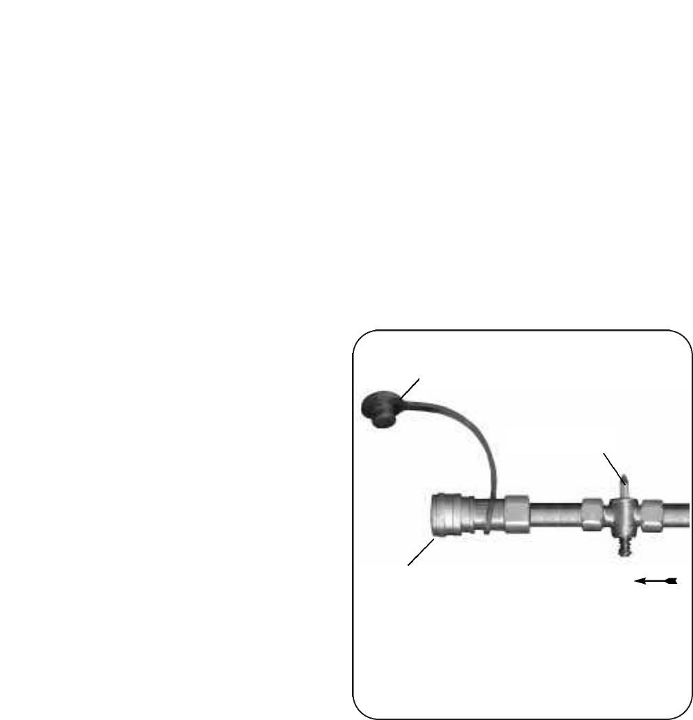
One Example of an Individual Shut-Off
Valve with the Quick-Connect Socket.
Connector Socket
Shut-off Valve
Gas Flow
Dust Cap
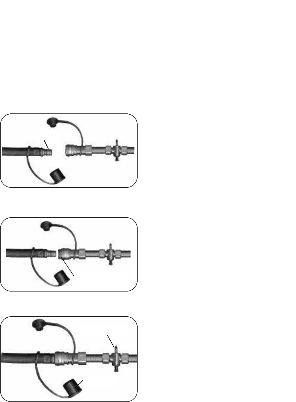
OPERATING THE QUICK-CONNECT
Follow all directions on tags attached to hose.
1. To connect the fuel-supply hose to the fuel
supply, the shut-off valve must be closed.
2. Remove the dust cap from the connector
socket by sliding the connector sleeve back to
release the plug. Remove the dust cap from the
plug.
3. Position the plug end of the fuel supply hose
into the sleeve opening.
4. Slide the connector sleeve back, firmly push
the fitting into the connector.
Model 7000N • Connecting to Natural Gas
(for specially equipped natural-gas grills only)
22
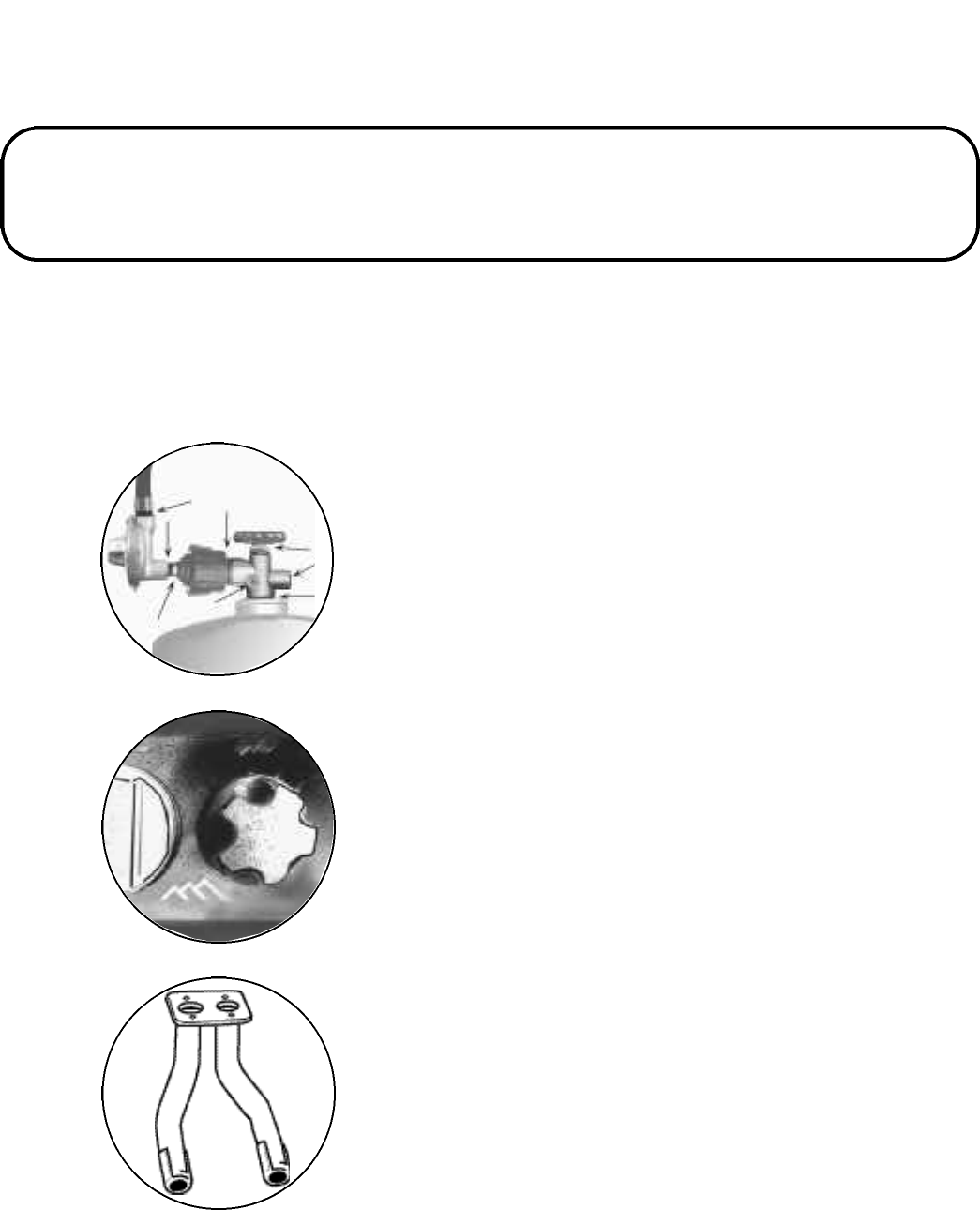
5. Push the plug into the connector until the
sleeve snaps forward to lock the fitting in
place. Turn on the shut-off valve. The flow of
gas to the appliance will be restricted if the
plug is not connected properly.
6. Test for gas leaks using an ammonia-free
soap and water solution.
TO DISCONNECT THE FUEL SUPPLY
1. Pull connector sleeve back and pull plug
out of socket. This will automatically shut off
gas to the appliance.
2. Close the shut-off valve and install the dust
caps on the socket and plug. Always turn off
the fuel supply at the shut-off valve when the
grill is not in use.
LEAK TEST CONNECTIONS
Test all the fuel supply connections using a
an ammonia-free soap and water solution
equally mixed. Never use fire to test for leaks.
Turn on the gas shut-off valve
1. Coat all connections of the fuel supply sys-
tem, especially at the quick-connect.
2. Watch for bubbles to indicate a leak.
3. If there is a leak, shut off the gas supply
and re-connect the hose to the socket.
Re-test for leaks.
Do not use the grill if a leak is detected that
cannot be corrected in this manner or if the
hose and connections become damaged.
Replace damaged components with only fac-
tory authorized parts.
Do not strain or kink the fuel-supply hose.
See that the hose is kept clear of surfaces that
become hot during use.
Plug
Connector Sleeve
Dust Cap
Shut-off Valve
Use and Care Directions Chapter 3
23
Leak Testing the Fuel Supply System
Lighting Instructions
Replacement Parts
Series 7000 Models
DANGER
To prevent fire or explosion hazard:
· Do not smoke while performing a leak
test.
·Do not permit any sources of ignition in
the area when testing for leaks.
· Perform leak tests outdoors only.
·Never perform a leak test near a fire or
flame.
How to Check the Fuel-Supply System for
Gas Leaks
1. Mix a solution of equal parts mild detergent
or liquid soap and water.
2. Turn off the burner-control knobs.
3. Turn the top knob of the fuel-supply cylinder
counterclockwise one rotation to open.
4. Apply the soap solution to all connections of
fuel-supply assembly.
If no soap bubbles appear, the grill is fine for
use.
If bubbles form at the connections, there is a
leak. In case of a leak, try tightening the joint. If
necessary, replace the faulty part with a
replacement part recommended by the manu-
facturer.
5. Turn off the knob on fuel-supply cylinder.
6. Turn on the burner-control knobs for a mo-
ment to release pressure in hose, then turn the
control knobs back off.
7. Wash off soapy solution with cold water and
towel dry.
WARNING! Do not attempt to repair the
cylinder valve. If it becomes damaged, the
cylinder must be replaced.
If you are unable to stop a leak, shut off the
gas supply at the cylinder valve. Remove the
cylinder from the grill. Call a gas appliance ser-
viceman or L.P. gas dealer. Do not use appli-
ance until the leak is fixed.
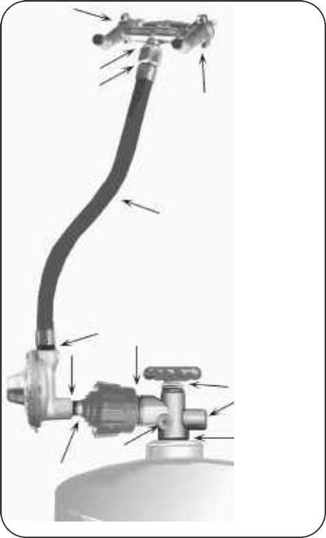
Leak Testing
Leak Testing the Fuel
Supply System
Arrows denotes primary areas
to check.
24
Perform a leak test each time the gas-supply
cylinder is connected to the regulator. Leak test
any time a part of the gas system is replaced.
Perform a leak test at least once each year
whether the L.P. gas supply cylinder has been
disconnected or not.
Have a dealer check the cylinder for deteriora-
tion after 10 years, according to DOT regula-
tions. Immediately replace cylinder if any is
found.
IMPORTANT! Inspect the gas-supply hose
regularly. If there are cuts, excessive abrasion,
or wear, replace the hose prior to operating the
appliance. Use only the hose replacement spec-
ified in the parts list for your grill.
IGNITER LIGHTING SYSTEM
The Igniter System consists of an igniter unit,
a gas-collector box, two ceramic electrodes,
and lead wires. Gas is collected in the metal
collector box located at the burner. When the
igniter knob is turned, an electric spark is creat-
ed at the ceramic electrodes. The gas is then
ignited by the spark.
To test: Watch the electrode tip(s) inside the
gas collector while activating the igniter. To
avoid a possible shock, do not touch the burner
or metal parts on igniter system while perform-
ing igniter test. A visible spark should jump
from the electrode. The spark gap is set when
the electrode is installed.
If there isn’t a spark, check the lead wires and
connections. The igniter wires should be kept
away from the grill bottom. Also check that the
ceramic electrodes in the collector box are not
broken.
Sometimes dirt and rust at and around the
electrode(s) can prevent an igniter spark. Clean
them with a degreaser or warm soapy water,
and dry. Remove rust from electrode tip(s) and
metal surfaces by lightly sanding with an emery
cloth or fine-grain sandpaper.
LIGHTING INSTRUCTIONS
(Read all the steps before beginning.)
STEP 1. Check the burner venturi tubes for
blockage from an insect nest (see, “CLEANING
THE BURNER VENTURI T U B E S ” ) .
STEP 2. Ensure that both of the burner-control
knobs are in the OFF position.
STEP 3. OPEN GRILL LID
WARNING: Attempting to light the grill with the
lid down could cause an explosion.
STEP 4. Go behind the grill and turn on the
fuel supply valve. One counter-clockwise turn is
generally enough to open the valve.
CAUTION: Do not stand with head or arms over
the grill.
STEP 5. To light using the igniter:
Push in and turn the right burner-control
knob counter-clockwise to the high setting.
STEP 6.
Immediately turn the igniter control knob
CLOCKWISE until you hear 4 or 5 clicks.
The burner should light.
Note: Turning the knob in the wrong direction
may loosen it. If this happens, simply press the
knob on firmly and turn it CLOCKWISE.
STEP 7.
If the burner fails to light properly, turn the burn-
er-control knob off. Also turn off the L.P. cylinder
knob. Wait five minutes before attempting to light
the burner again. This will allow time for released
gas to disperse.
HINT: If the burner does not light after trying
again, turn off burner-control knob, the L.P. cylin-
der knob and try match lighting the grill once the
gas has cleared.
Lighting Instructions
25
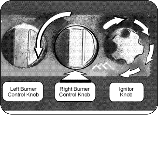
Operating the Control Knobs
Gas control knobs PRESS IN and rotate counter-
clockwise.
ROTATE THE IGNITER KNOB CLOCKWISE.
MATCH LIGHTING
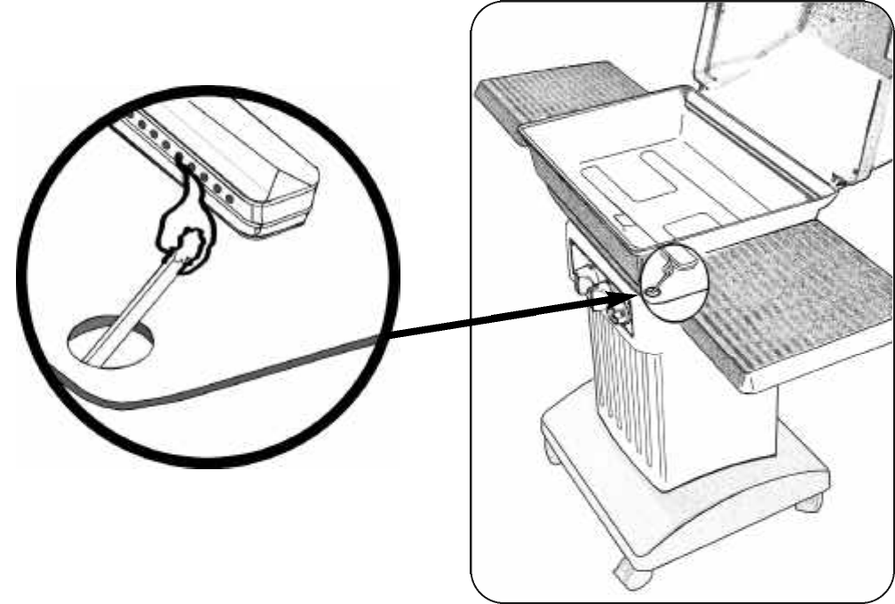
IMPORTANT! The match-lighting hole is found
under the front right corner of the grill bottom.
When match lighting the grill, use the gas-control
knob on your RIGHT-HAND side (closest to the
match-lighting hole).
Repeat steps 1 to 4 of “Lighting Instructions.”
STEP 5. To match light: push down and turn
the RIGHT burner control knob counter-clock-
wise to the high setting.
STEP 6.
IMMEDIATELY strike a long wooden match and
position the burning match through match-light-
ing hole in the grill bottom. Extend the flame
near a burner port in the bottom edge of the
burner. The burner should light.
To light the other side of the burner, press in
and turn the opposite control knob. The flame
will track around the burner. Allow grill to preheat
with the grill lid closed for five minutes before
cooking.
CAUTION: Do not touch any hot grill parts.
The outside of the grill bottom becomes very
hot during use. It may be necessary to use pro-
tective gloves.
HOW TO SHUT OFF THE GRILL
STEP 1. Turn the burner-control knob(s) off.
The burner flame will go out.
STEP 2. Turn off the top L.P. cylinder valve by
turning the knob in a clockwise direction until it
stops.
IMPORTANT: Always have the gas shut off at
the L.P. cylinder valve when the grill is not in
use. The L.P. cylinder has a leak detection fea-
ture which will restrict the amount of gas flow to
the burner if the tank shut-off valve has not
been turned off prior to the next use.
Locating the Match Lighting Hole
The match lighting hole is located beneath the
lower right corner of the grill-bottom casting.
26
Lighting Instructions
CONTROL SETTINGS
The high flame setting is for quick searing of
meat. Sear foods, then finish cooking on a lower
setting.
Amedium setting works best for cooking
steaks, pork chops, and hamburgers.
The lowest setting works well for all roasts and
rotisserie foods. Even thick steaks, when seared
on a high setting first, will have a better texture
and be more juicy cooked on low.
DUAL BURNER COOKING SYSTEM
The grill’s burner may be operated to cook on
either side or both sides at once. This allows for
various styles of cooking.
1. Use a direct heat source when browning
meat or cooking hot dogs and hamburgers.
Check the food often.
2. Cook large-size foods (such as roasts,
turkey, or duck) on a low, direct heat. Place food
and water in foil pan with corrugated bottom,
adding water as needed.
3. If doing skillet or stir-fry cooking, limit the
amount of oil and direct heat used.
4. Cook foods that burn easily over an indirect
heat. Light one side of the burner and place the
food on the other side for cooking. The food will
cook slower but should be more tender. This
method of cooking also reduces grease flare-up.
Add a small pan of water to help keep meat
moist, replace the water as needed.
5. Casseroles can be cooked in oven-proof or
foil pans using indirect heat.
6. Cook two foods at once using different set-
tings.
7. To add smoked flavor, try adding wood chips
in apple, mesquite, and hickory flavors.
TO BREAK IN A NEW GRILL
Before using it for the first time; operate the
grill with lid closed on a low setting for about 15
minutes. This will help burn away oil and the
smell of new paint. After the oil has burned
away, check the burner flame.
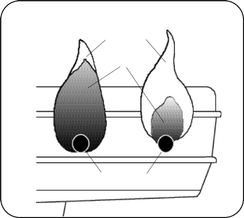
BURNER’S FLAME
Keep the grill lid closed and the grids in place.
Inspect the burner’s flame by carefully looking
below and through the air-supply openings in
the grill bottom.
Agood flame should be blue with some yellow
tip coming from the burner holes. Some yellow
tips on flames up to 1" in length are acceptable
as long as no carbon or soot deposits appear.
If flames are excessively yellow and irregular,
the oil residue may not be completely burned
off, or the venturi may not be properly posi-
tioned over the orifice(s). Allow grill to cool
before repositioning venturi over valve.
After a grill has been in use for a while it may
begin to have a more yellow flame. A build up of
food deposits, fats, or cooking seasonings can
cause yellowing of flames. Try cleaning the
burner to remove built-up residue. Check for
clogged burner holes or blocked venturi tubes.
Regular use of your grill will actually help keep
it operating more smoothly. It is not unusual for
similar units to heat a little differently.
FLAME CHECK
BAD FLAMEGOOD FLAME
Holes in burner
YELLOW
BLUE
Checking the Burner Flame 27
Using Your Gas Grill

Replacement parts are available direct from our warehouse. Some components are not available
preassembled and may be ordered separately. For convenience, the following parts list is provid-
ed along with a representation of the items listed. Charges for replacement parts and shipping
may apply.
For warranty replacements, proof of ownership and date of purchase is required.
Please call 888-869-5454 to receive a return authorization number before returning any grill com-
ponents.
To order parts call toll free in the USA: 888-869-5454 or write to:
the Great Outdoors Grill Company
7980 East American Drive
Joplin, Missouri U.S.A. 64804
Replacement Parts for Series 7000 Grills
30
Parts Enclosed
quantity description part number
1 Main Hardware Bag AM000505
1 Hardware Bag “A”
4 1⁄4 x 20 x 3⁄4" Bolt AM000105
4 1⁄4 x 20 Hex Keps Nut AM000904
1 Hardware Bag “B”
4 1⁄4 x 20 x 1" Bolt AM000106
4 1⁄4 x 20 Hex Keps Nut AM000904
1 Hardware Bag “C”
8 1⁄4 x 20 x 3⁄4" Bolt AM000105
8 1⁄4 x 20 Hex Keps Nut AM000904
1 Hardware Bag “D”
2 1⁄4 x 1 1⁄8" Hinge Pin AM000908
2 Hairpin AM000909
4 1⁄4 x 20 x 5⁄8" Bolt AM000207
4 1⁄4 x 20 Hex Keps Nut AM000904
2 Handle Gasket AM000704
Long detachable power-supply cords or extension
cords can also be used with care. The marked elec-
trical rating of the cord set or extension cord should
be at least as great as the electrical rating of the ap-
pliance. If the appliance is of the grounded type, the
extension cord should be a grounding-type 3 wire
cord. Use outdoor extension cords with a surface
marked with suffix letters “W-A” and with a tag stating
“Suitable for Use with Outdoor Appliances.”
Keep the connection to an extension cord away
from water and off the ground. Arrange the cord so
that it will not drape over the counter top or tabletop
where it can be pulled or tripped over.
Do not clean any electrical product with a water
spray or the like. Store electrical products indoors out
of reach of children when not in use.
Parts Enclosed
quantity description part number
1 Side Table ( of 2) SDTBL-BLK
1 Grate AF000205
1 package Ceramic Briquettes AQ000102
2 piece Cooking Grid AF000105
1 Warming Rack AF000303
1 Grill Lid TOP400-BLK
1 Lid Handle AP000102
2 Handle Standoffs AZ000802
1 Heat Shield AI000204
1 Aluminum Drip Pan* AI000302
1 Fuel Cylinder ** AW000202
1 Wire Cylinder Retainer ** AF000402
NOTE: All hardware is stainless steel.
* (this is a standard 1 lb. aluminum loaf baking pan)
** (not included with natural gas models)
Model 7000N
only
31
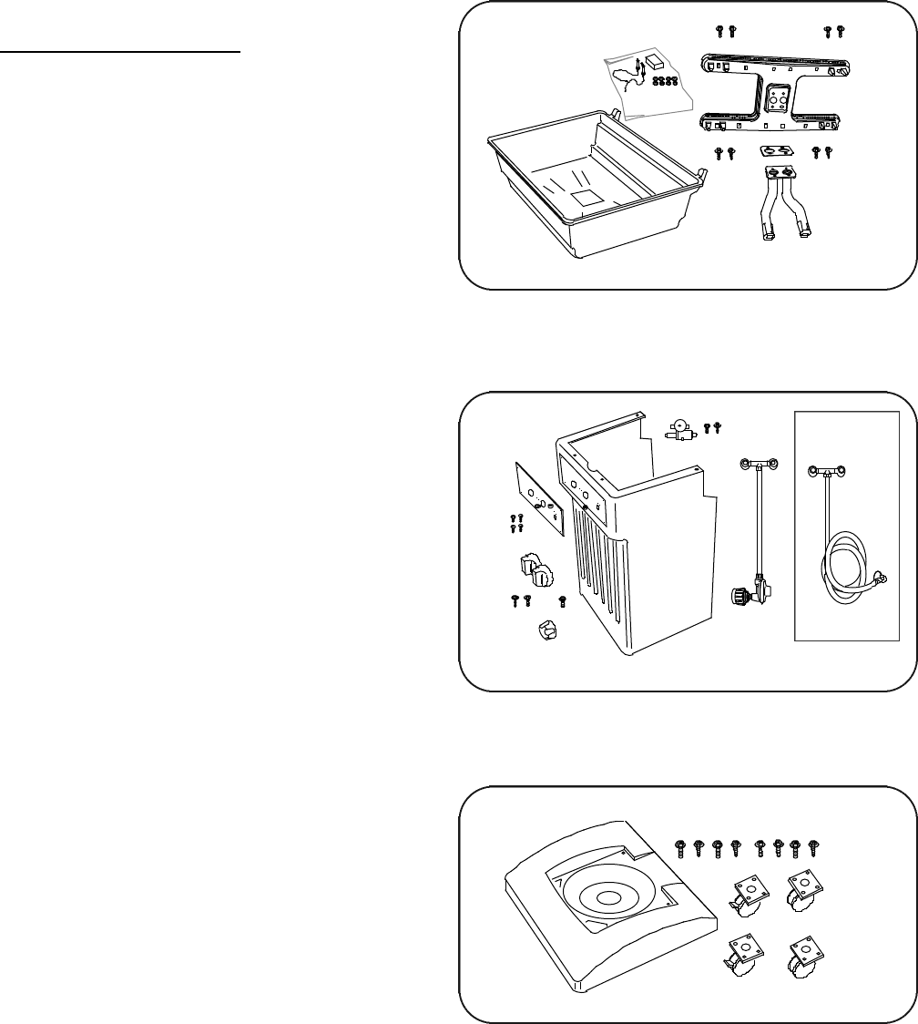
Base Assembly
Breakdown of Preassembled Components
Pillar Assembly
Bottom/Burner Assembly
Preassembled Components
quantity description part number
1 Bottom/Burner Assembly
consisting of:
1 Cast Brass Burner AZ001503
1 Venturi Tube w/gasket AZ000506
8 #8-32 x 1⁄2" Screw AM000603
1 Bottom Grill Casting BTM400-BLK
1 Pillar Assembly
consisting of:
1 Pillar Casting PILLAR-COPPERVN
4 #10-24 x 3⁄8" Screw AM000203
1 Printed Control Plate AI000103
210 x 24 x 1⁄2" Bolt AM000103
1 Valve/Regulator/Hose AL000103
1 Rotary Igniter Unit kit AN000303
2 Control Knobs AZ000703
1 Igniter Knob AZ000603
Natural-Gas Model 7000N only:
1 Natural-Gas Valve/Hose Assembly AL000203
1 Base Assembly
consisting of:
1 Base Casting BASE-BLK
8 1⁄4 x 20 x 1⁄2" Bolt AM000303
2 Locking Caster AH000103
2 Caster AH000203
NOTE: All hardware is stainless steel.
