Chamberlain Group The 1D8088-1 MyQ - Garage Door Controller User Manual 114A4832
Chamberlain Group Inc, The MyQ - Garage Door Controller 114A4832
UserManual.wiki
>
Chamberlain Group The
>
1D8088-1 User Manual
>
User manual 1 of 2
Contents
1.
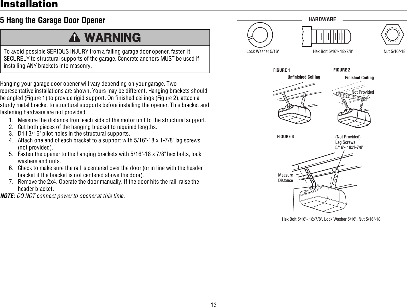
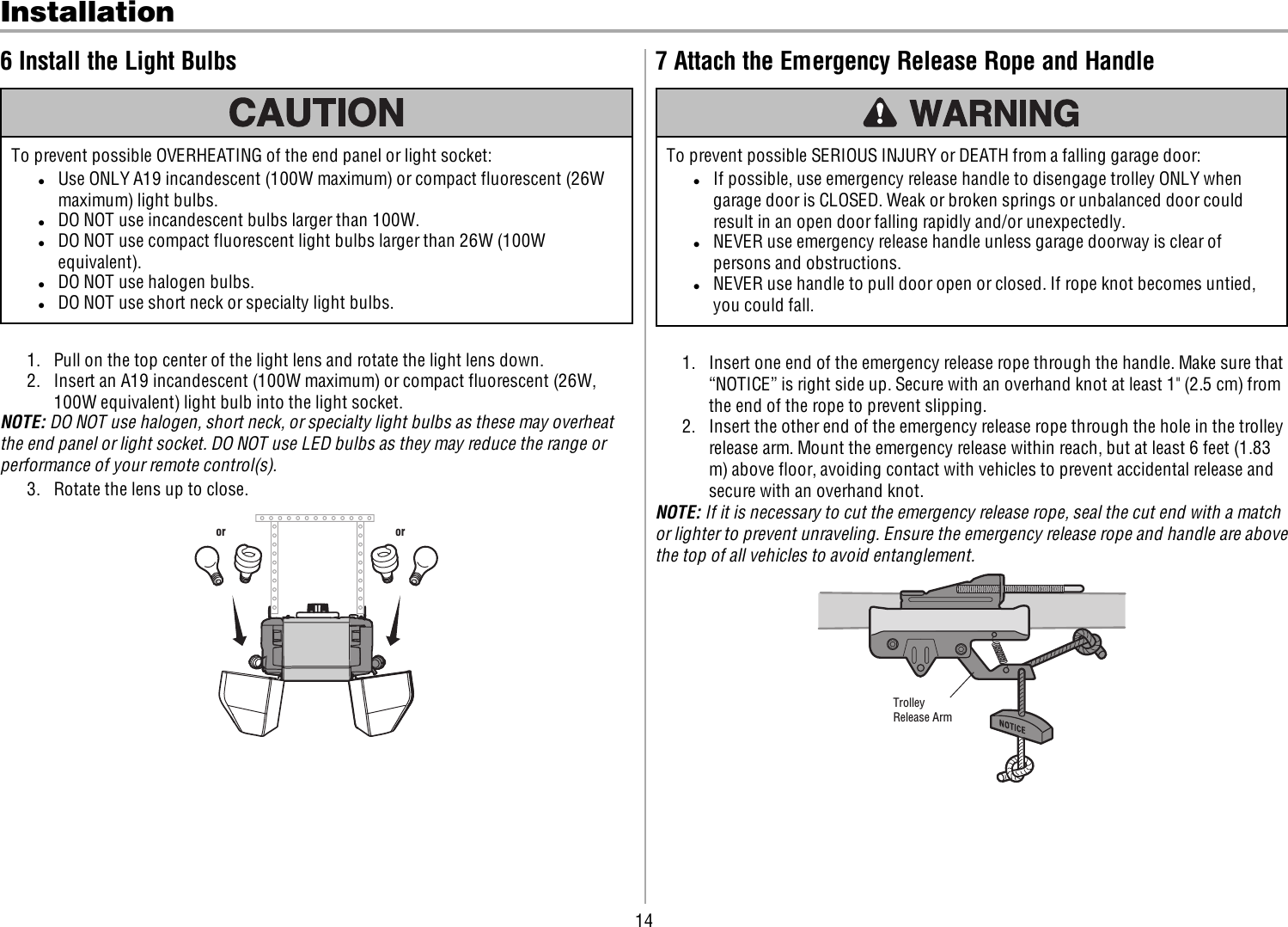
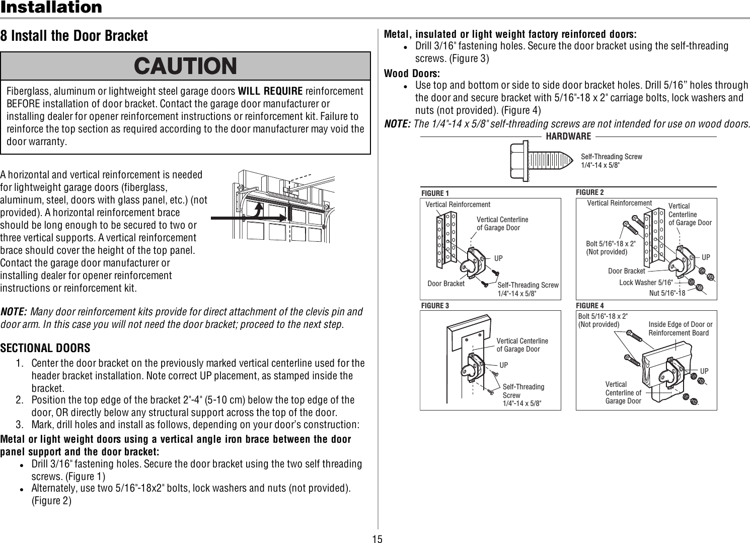
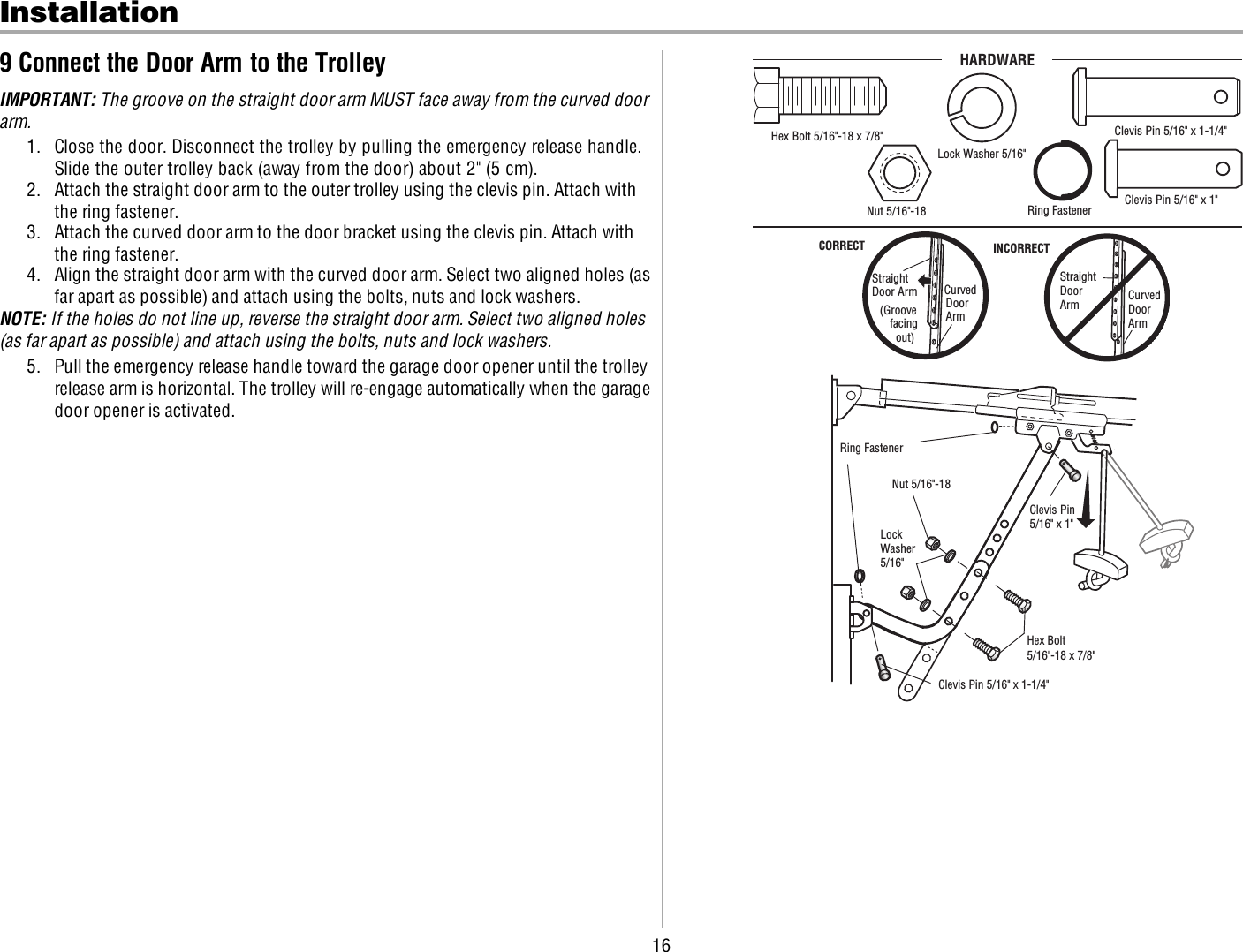
User Manual
2.
User manual 1 of 2
3.
User manual 2 of 2
User manual 1 of 2
Navigation menu
Upload a User Manual
Namespaces
Wiki Guide
HTML
PDF
Info
Views
User Manual
Discussion / Help
Navigation