Chamberlain Group The 2D1911 MyQ Remote LED Light Assmebly User Manual 114A4961wmkD5 flattened
Chamberlain Group Inc, The MyQ Remote LED Light Assmebly 114A4961wmkD5 flattened
User Manual_20171205_v1 - 11_11627318 8500W Manual - 114A4961wmkD5
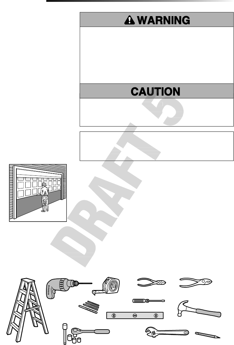
•Please read this manual and the
enclosed safety materials carefully!
•The door WILL NOT CLOSE unless the
Protector System
®
and cable tension
monitor are connected and properly aligned.
•Periodic checks of the garage door opener
are required to ensure safe operation.
•The model number is located on the
front cover of the opener.
•This garage door opener is ONLY
compatible with MyQ
®
and Security+2.0
®
accessories.
•Attach warning labels to the location
indicated on label.
This product is intended for installation only by trained garage door technicians. This product may
require adjustments to door springs and/or track configurations. This product is not intended for
use on low headroom tracks with outside pickup drum or garage doors utilizing extension springs.
For Residential Use
Install On Sectional Doors With Torsion Assemblies Only
Wall Mount Wi-Fi® Garage Door Opener
Model 8500W
LiftMaster
300 Windsor Drive
Oak Brook, IL 60523
Register your garage door opener to receive
updates and offers from LiftMaster
Take a photo of the
camera icon including
the points ( ).
Send it in by texting
the photo to 71403
(US) or visit
www.liftmaster.photo
(Global)
SM
ead this manual and the
enclosed safety materials car
efully!
The door WILL NOT CLOSE unless the
and cable tension
e connected and properly aligned.
Periodic checks of the garage door opener
ead this manual and the
oduct is intended for installation only by trained garage door technicians. This product may
require adjustments to door springs and/or track configurations. This product is not intended for
use on low headroom tracks with outside pickup drum or garage doors utilizing extension springs.
oduct is intended for installation only by trained garage door technicians. This product may
require adjustments to door springs and/or track configurations. This product is not intended for
2
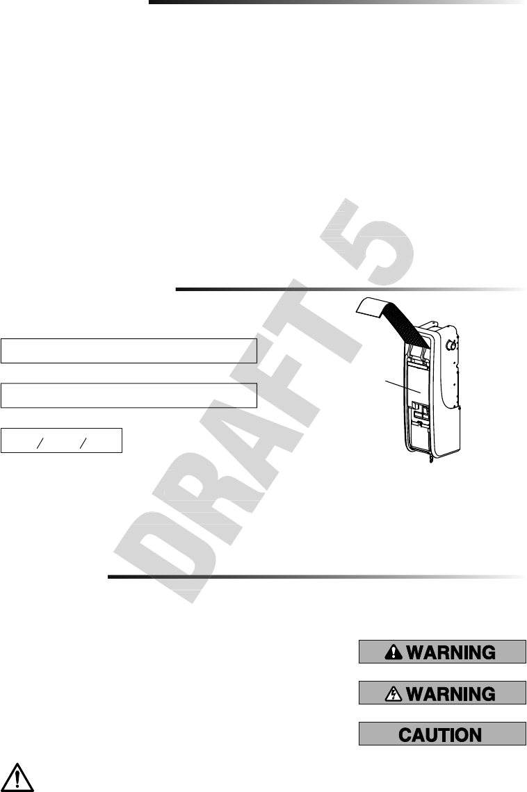
Introduction
MyQ® Serial Number
When you see these Safety Symbols and Signal Words on the following pages, they
will alert you to the possibility of serious injury or death if you do not comply with the
warnings that accompany them. The hazard may come from something mechanical or
from electric shock. Read the warnings carefully.
When you see this Signal Word on the following pages, it will alert you to the possibility of
damage to your garage door and/or the garage door opener if you do not comply with the
cautionary statements that accompany it. Read them carefully.
Mechanical
Electrical
Safety Symbol and Signal Word Review
This garage door opener has been designed and tested to offer safe service provided it is installed, operated, maintained and tested in
strict accordance with the instructions and warnings contained in this manual.
Table of Contents
MYQ SERIAL NUMBER 2
UNATTENDED OPERATION 2
INTRODUCTION 2
Safety Symbol and Signal Word Review ...... 2
Planning ........................................................ 3
Before You Connect with Your Smartphone 4
Preparing Your Garage Door ........................ 5
Tools Needed ................................................ 5
Carton Inventory ........................................... 6
Included Accessories ....................................6
Hardware ....................................................... 6
Additional Items You May Need ................... 6
ASSEMBLY 7
Attach the Collar to the
Garage Door Opener .....................................7
Attach Mounting Bracket to
Garage Door Opener .....................................8
INSTALLATION 8
Position and Mount the
Garage Door Opener .....................................9
Attach the Emergency Release Rope
and Handle .................................................. 10
Install Automatic Door Lock .......................10
Attach the Cable Tension
Monitor (Required) .....................................11
Install the Door Control
(Smart Control Panel) ................................. 12
Install MyQ® LED Remote Light ................. 13
Install the Protector System® ....................14
Connect Power ............................................ 17
Install the Battery Backup ...........................19
ADJUSTMENT 20
Program the Travel ..................................... 20
Test the Safety Reversal System ................ 21
Test the Protector System® .......................21
Test Cable Tension Monitor ........................ 22
Test Automatic Door Lock .......................... 22
To Open the Door Manually ........................22
OPERATION 23
Using Your Garage Door Opener ................24
Connect with Your Smartphone ................. 25
Using the Door Control ...............................26
PROGRAMMING 28
893MAX Remote Control ............................28
Reprogramming MyQ® LED
Remote Light...............................................29
To Erase the Memory .................................. 29
MAINTENANCE 30
Care of Your Garage Door Opener ..............30
TROUBLESHOOTING 31
Diagnostic Chart .......................................... 31
Additional Troubleshooting .........................32
REPAIR PARTS 34
Installation Parts .........................................34
Garage Door Opener Assembly Parts .........35
CONTACT INFORMATION 35
ACCESSORIES 36
WARRANTY 37
Date of Purchase:
Write down the following information for future reference:
Product S/N:
MyQ® Serial Number:
Serial Numbers
WARNING: This product can expose you to chemicals including lead, which are known to the State of California to cause
cancer or birth defects or other reproductive harm. For more information go to www.P65Warnings.ca.gov
Unattended Operation
The Timer-to-Close (TTC) feature, the MyQ® Smartphone Control app, and MyQ® Garage Door and Gate Monitor are examples of
unattended close and are to be used ONLY with sectional doors. Any device or feature that allows the door to close without being in the
line of sight of the door is considered unattended close. The Timer-to-Close (TTC) feature, the MyQ® Smartphone Control, and any other
MyQ® devices are to be used ONLY with sectional doors.
MyQ Remote LED Light must be installed to enable use of Timer To Close or MyQ Smartphone Control of the door.
Safety Symbol and Signal Word Review
Safety Symbol and Signal Word Review
unattended close and are to be used ONLY with sectional doors. Any device or feature that allows the door to close without bein
line of sight of the door is considered unattended close. The Timer-to-Close (TTC) feature, the MyQ
devices are to be used ONLY with sectional doors.
MyQ Remote LED Light must be installed to enable use of Timer To Close or MyQ Smartphone Control of the door.
Unattended Operation
The Timer-to-Close (TTC) feature, the MyQ
®
Smartphone Control app, and MyQ
unattended close and are to be used ONLY with sectional doors. Any device or feature that allows the door to close without bein
line of sight of the door is considered unattended close. The Timer-to-Close (TTC) feature, the MyQ
devices are to be used ONLY with sectional doors.
MyQ Remote LED Light must be installed to enable use of Timer To Close or MyQ Smartphone Control of the door.
Test Automatic Door Lock .......................... 22
To Open the Door Manually ........................22
OPERATION 23
Using Your Garage Door Opener ................24
Connect with Your Smartphone ................. 25
WARRANTY 37
Test Cable Tension Monitor ........................ 22
Test Automatic Door Lock .......................... 22
To Open the Door Manually ........................22
OPERATION 23
Using Your Garage Door Opener ................24
Connect with Your Smartphone ................. 25
ACCESSORIES 36
WARRANTY 37
3
Introduction
Planning
Survey your area to see if any of the conditions below apply to your installation.
Depending on your requirements, additional materials may be required.
THIS DOOR OPENER IS COMPATIBLE WITH:
• Doors that use a torsion bar and springs. The torsion bar must be 1" (2.5 cm)
diameter. NOT compatible with reverse wound drums.
• 4-6" (10-15 cm) drums, not to be used on tapered drums over 6" (15 cm).
• High lift (up to 54" (137.2 cm) high) and standard lift sectional doors up to 14 ft.
(4.3 m) high.
• Doors up to 18 ft. (5.5 m) wide.
• Doors up to 180 sq. ft. (16.7 sq. m).
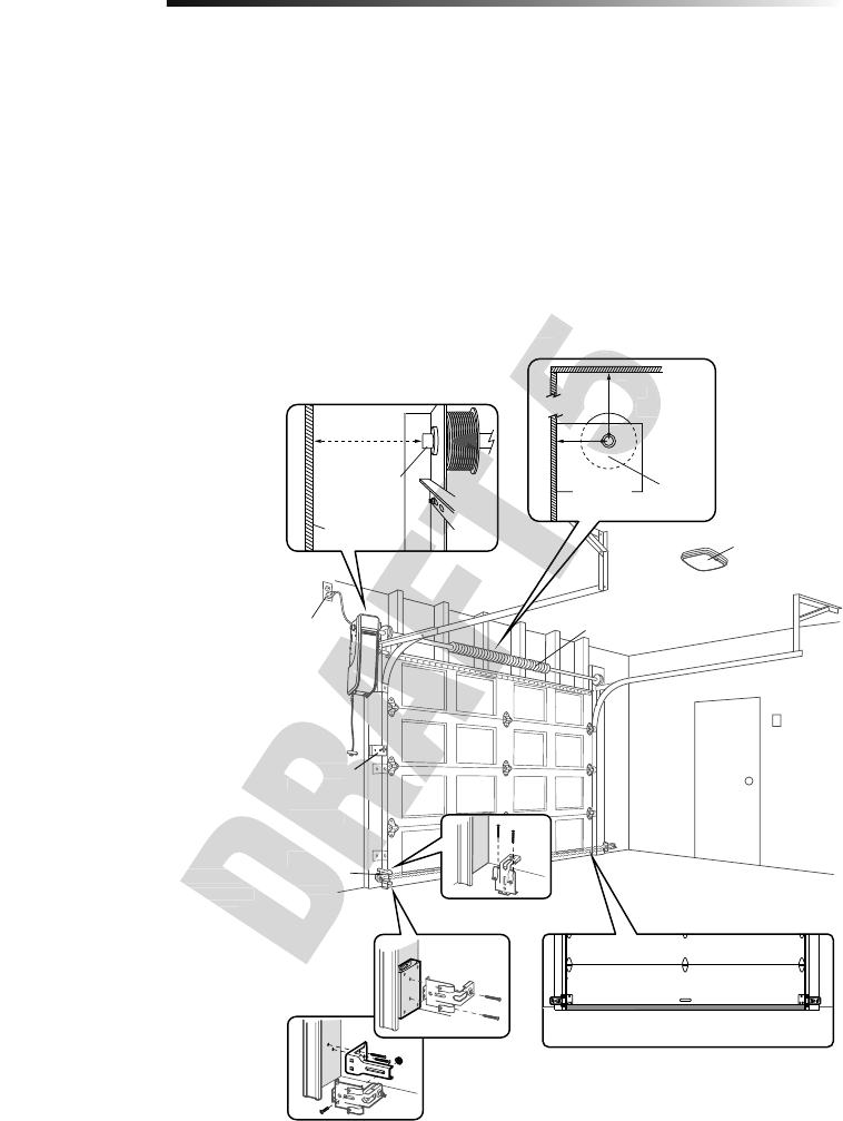
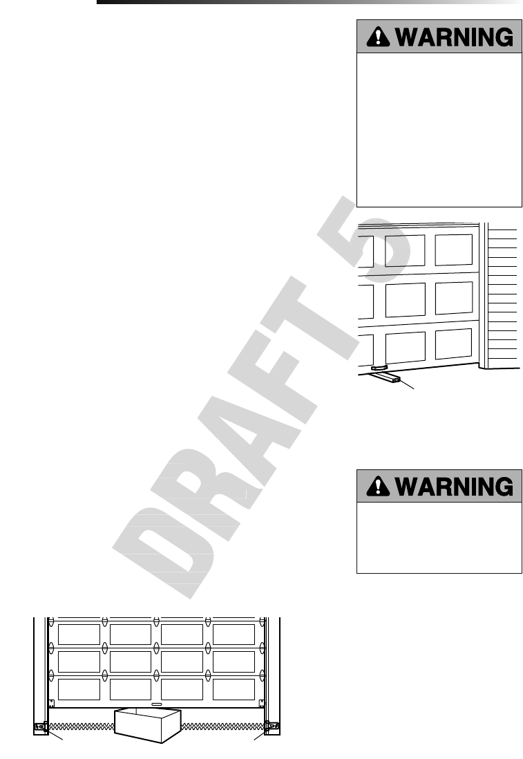
Review or inspect proposed installation area. The door opener can be installed on the left
or right side of door. Select the side that meets the requirements listed below.
a. Must have minimum of 2.5" (6.4 cm)
between the wall and the center of the
torsion bar.
b. Must have minimum of 3" (7.6 cm)
between the ceiling and the center of
torsion bar.
c. Must have minimum of 8.5" (21.6cm)
between the side wall (or obstruction)
and the end of torsion bar.
d. The torsion bar must extend at least
1.5" (3.81 cm) past the bearing.
This may vary depending on your
installation requirements.
e. An electric outlet is required within
6ft. (1.83 m) of the installation area.
If outlet does not exist, contact a
qualifi ed electrician.
f. Depending upon building
construction, extension brackets or
wood blocks may be needed to install
safety reversing sensors and cable
tension monitor.
g. Alternate fl oor mounting of the
safety reversing sensors will require
hardware (not provided).
h. Any gap between the fl oor and the
bottom of the door must not exceed
1/4" (6 mm), otherwise the safety
reversing sensors may not work
properly.
NOTE: Inspect the torsion bar while the
door is raised and lowered. It is important
that there is no noticeable movement up
and down or left and right. If the movement
is not corrected, the life of the garage door
opener will be greatly reduced.
a
b
h
c
d
e
f
g
Torsion
bar
2.5"
(6.4 cm)
3"
(7.6 cm)
Wall or
obstruction
Torsion bar
8.5"
(21.6cm)
Safety
reversing
sensor
MyQ® LED
Remote Light
(Not provided)
Automatic
door lock
(Not
provided)
Door spring
safety reversing sensors will require
Any gap between the fl oor and the
bottom of the door must not exceed
1/4" (6 mm), otherwise the safety
Safety
reversing
sensor
wood blocks may be needed to install
Automatic
door lock
(Not
provided)
b
3"
(7.6
b
(7.6
4
Before You Connect with Your Smartphone
Introduction
Monitor and control your garage door from anywhere using the MyQ® app.
BEFORE YOU BEGIN:
You will need:
• Wi-Fi enabled smartphone, tablet or laptop
• Broadband Internet Connection
• Wi-Fi signal in the garage (2.4 Ghz, 802.11b/g/n required)
• Password for your home network (router's main account, not guest network)
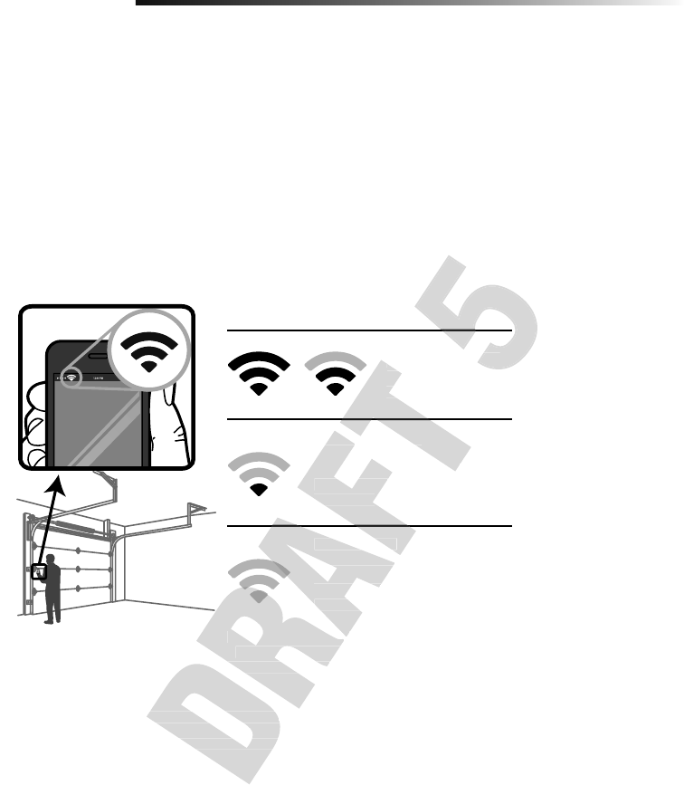
TEST THE WI-FI SIGNAL STRENGTH
Make sure your mobile device is connected to your Wi-Fi network. Hold your mobile
device in the place where your garage door opener will be installed and check the Wi-Fi
signal strength.
For compatible router specifi cations and help, visit WiFiHelp.LiftMaster.com.
See page 25 to connect the garage door opener to a mobile device.
Check Signal Strength. If you see:
Wi-Fi signal is strong.
The garage door
opener will connect to
your Wi-Fi network.
Wi-Fi signal is weak.
The garage door opener may connect
to your Wi-Fi network. If not, try one
of the options below to improve the
Wi-Fi signal:
No Wi-Fi signal.
The garage door opener will not be
able to connect to your Wi-Fi network.
Try one of the options below to
improve the Wi-Fi signal:
• Move your router closer to the garage door opener to
minimize interference from walls and other objects
• Buy a Wi-Fi range extender
For compatible router specifi cations and help, visit WiFiHelp.LiftMaster.com.
For compatible router specifi cations and help, visit WiFiHelp.LiftMaster.com.
See page 25 to connect the garage door opener to a mobile device.
• Move your router closer to the garage door opener to
minimize interference from walls and other objects
• Buy a Wi-Fi range extender
No Wi-Fi signal.
The garage door opener will not be
able to connect to your Wi-Fi network.
Try one of the options below to
improve the Wi-Fi signal:
• Move your router closer to the garage door opener to
Wi-Fi signal is weak.
The garage door opener may connect
to your Wi-Fi network. If not, try one
of the options below to improve the
Wi-Fi signal:
No Wi-Fi signal.
The garage door opener will not be
The garage door
opener will connect to
your Wi-Fi network.
Wi-Fi signal is weak.
The garage door opener may connect
to your Wi-Fi network. If not, try one
Check Signal Strength. If you see:
Wi-Fi signal is strong.
Check Signal Strength. If you see:
Wi-Fi signal is strong.
5
Introduction
Preparing Your Garage
Door
BEFORE YOU BEGIN:
• Disable locks.
• Remove any ropes connected to the
garage door.
Complete the following test to make sure
the garage door is balanced and is not
sticking or binding:
1. Lift the door halfway up. Release
the door. If balanced, it should stay
in place, supported entirely by its
springs.
2. Raise and lower the door to check for
binding or sticking.
3. Doors heavier than 650 lbs. should
NOT open or fall rapidly.
If your door binds, sticks, or is out of
balance, call a trained door systems
technician.
4. Verify equal cable tension on each
side of door. Cable tension should
remain equal during the entire travel
of the door.
To prevent damage to garage door and opener:
• ALWAYS disable locks BEFORE installing and operating the opener.
• ONLY operate garage door opener at 120V, 60Hz to avoid malfunction and
damage.
To prevent possible SERIOUS INJURY or DEATH:
• ALWAYS call a trained door systems technician if garage door binds, sticks, or is
out of balance. An unbalanced garage door may NOT reverse when required.
• NEVER try to loosen, move or adjust garage door, door springs, cables, pulleys,
brackets or their hardware, ALL of which are under EXTREME tension.
• Disable ALL locks and remove ALL ropes connected to garage door BEFORE
installing and operating garage door opener to avoid entanglement.
• This opener system is equipped with an unattended operation feature. The door
could move unexpectedly. NO ONE SHOULD CROSS THE PATH OF THE MOVING
DOOR.
Tools Needed
During assembly, installation and adjustment of the garage door opener, instructions will
call for hand tools as illustrated below.
Pliers
Wire Cutters
Claw Hammer
Screwdriver
Adjustable End Wrench
1/4", 5/16", and 3/8" Sockets
and Wrench with 6" Extension
Drill Tape Measure
Stepladder
Pencil
5/32", 3/16", 5/16"
and 3/4" Drill Bits
Level
Sectional Door
SPECIFICATIONS
Volts . . . . . . . . . . . . . . . . . . . . . . . . . . . . . . . . . . . . . . . . . . . .120 Vac - 60 Hz, ONLY
Current . . . . . . . . . . . . . . . . . . . . . . . . . . . . . . . . . . . . . . . . . . . . . . . . . . . . . 1.5 AMP
LED Light Current (independently powered) . . . . . . . . . . . . . . . . . . . . . . . . 0.2 AMPS
During assembly, installation and adjustment of the garage door opener, instructions will
. . . . . . . . . . . . . . . . . . . . . . . . . . . . . . . . . . . . . . . . . . . . . . . . . . . . .
LED Light Current (independently powered)
SPECIFICATIONS
. . . . . . . . . . . . . . . . . . . . . . . . . . . . . . . . . . . . . . . . . . . .
. . . . . . . . . . . . . . . . . . . . . . . . . . . . . . . . . . . . . . . . . . . . . . . . . . . . .
LED Light Current (independently powered) . . . . . . . . . . . . . . . . . . . . . . . .
To prevent damage to garage door and opener:
• ALWAYS disable locks BEFORE installing and operating the opener.
• ONLY operate garage door opener at 120V, 60Hz to avoid malfunction and
To prevent damage to garage door and opener:
• ALWAYS disable locks BEFORE installing and operating the opener.
• ONLY operate garage door opener at 120V, 60Hz to avoid malfunction and
6
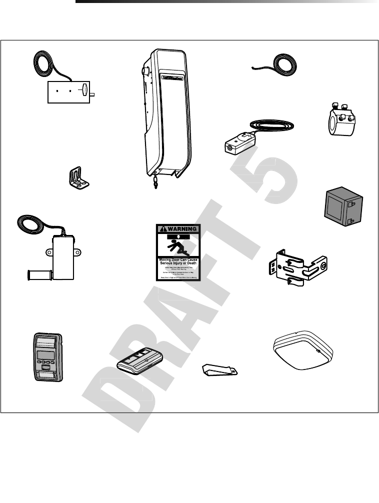
Carton Inventory
If anything is missing, carefully check the packing material.
Introduction
Automatic Garage Door Lock
Model 841LM
with 2-Conductor White and White/Black
Bell Wire with Connector
NOTE: Older model 24V door locks
are incompatible
2 Conductor Bell Wire
White and White/Red
Garage Door Opener
Cable Tension Monitor with
2-Conductor Green/White Bell Wires
Mounting Bracket
Collar with
Set Screws
Safety Reversing Sensor Bracket (2)
The Protector System®
(2) Safety Reversing Sensors
(1 Sending Sensor and
1 Receiving Sensor) with
2-Conductor White and
White/Black Bell Wire attached
Safety Labels
and Literature
Battery Model 485LM
Hardware
Additional Items You May Need
Extension brackets (Model 041A5281-1)
or wood blocks: Depending upon garage
construction, extension brackets or wood
blocks may be needed to install the safety
reversing sensor.
Fastening hardware: Alternate fl oor
mounting of the safety reversing sensor
will require hardware not provided.
90˚ connector for cable conduit or fl ex
cable adapter: Required for permanent
wiring.
Screw #10-32 (2)
Screw 14-10x2" (4)
Handle
Rope
Screw 1/4"-20x1/2" (2)
Drywall Anchor (Screw-In) (2)
Screw 8-32x1" (2)
Screw 6ABx1-1/4" (2)
Drywall Anchor (2)
Screw 6-32x1" (2)
Carriage Bolt 1/4"-20x1/2" (2)
Wing Nut 1/4"-20 (2)
REMOTE LIGHT HARDWARE:
MyQ® LED Remote Light Model 827LM
Drywall Anchor (Screw-In) (2)
Screw #6x1" (2)
Included Accessories
Remote Control
Visor Clip
3-Button Premium
Remote Control
Model 893MAX (1)
MyQ® LED Remote Light
Model 827LM
(Garage Door Opener Light)
with Hardware Bag
Smart Control Panel
Model 880LMW
3-Button Premium
Remote Control
Model 893MAX (1)
3-Button Premium
Safety Labels
and Literature
Safety Labels
White/Black Bell Wire attached
The Protector System
®
(2) Safety Reversing Sensors
(1 Sending Sensor and
1 Receiving Sensor) with
2-Conductor White and
White/Black Bell Wire attached
The Protector System
®
(2) Safety Reversing Sensors
(1 Sending Sensor and
1 Receiving Sensor) with
2-Conductor White and
White/Black Bell Wire attached
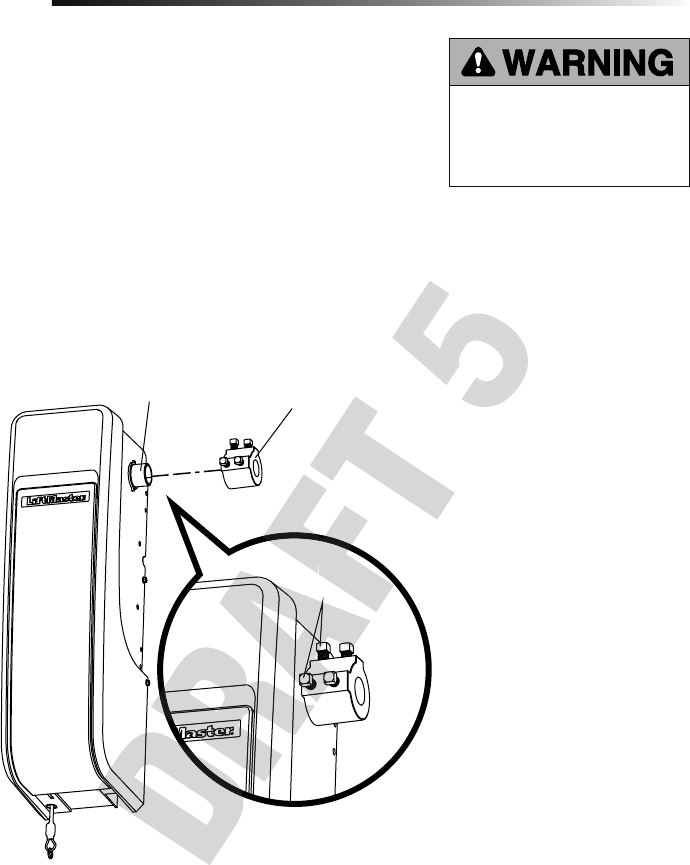
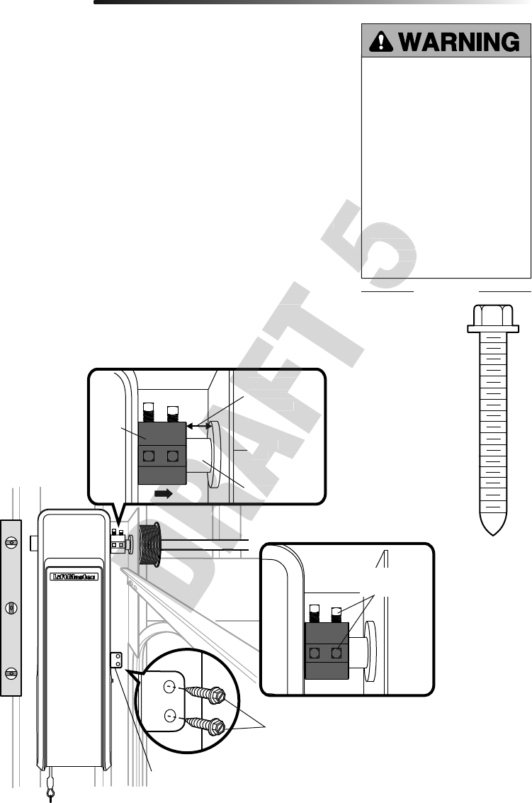
7
Set
Screws
Collar
Motor
Shaft
To avoid installation diffi culties, do not run the garage door garage door opener until
instructed to do so.
The garage door opener can be installed on either side of the door (see Planning section
page 3). The illustrations shown are for installation on the left side.
1. Loosen the set screws.
2. Attach collar to the garage door opener motor shaft. The side of the collar with the
larger hole should be placed on the motor shaft. Ensure that the collar is seated all
the way on motor shaft until stop is reached.
3. Position the collar so the screws are facing out and are accessible when attached to
the torsion bar.
4. Securely tighten the 2 square head set screws closest to the motor shaft by turning
the screws 1/4 - 1/2 turn after making contact with the motor shaft.
Attach the Collar to the Garage Door Opener
Assembly
1
To prevent possible SERIOUS INJURY
or DEATH, the collar MUST be properly
tightened. The door may NOT reverse
correctly or limits may be lost due to
collar slip.
Set
Screws
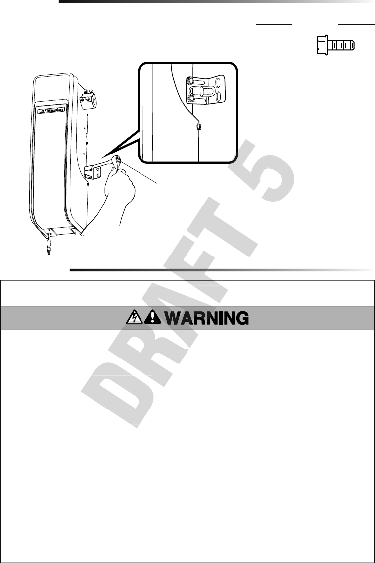
8
Installation
IMPORTANT INSTALLATION INSTRUCTIONS
To reduce the risk of SEVERE INJURY
or DEATH:
Attach Mounting Bracket to Garage Door Opener
2
1. Loosely attach slotted side of mounting bracket to the same side of the garage door
opener as the collar, using screws provided.
NOTE: Do not tighten screws until instructed.
Socket Wrench
Assembly
HARDWARE
Screw
#10-32 (2)
1. Read and follow all warnings and instructions.
2. Install garage door opener ONLY on properly balanced
and lubricated garage door. An improperly balanced
door may NOT reverse when required and could result in
SEVERE INJURY or DEATH.
3. ALL repairs to cables, spring assemblies and other
hardware MUST be made by a trained door systems
technician BEFORE installing opener.
4. Disable ALL locks and remove ALL ropes connected
to garage door BEFORE installing opener to avoid
entanglement.
5. Where possible, install the door opener 7 feet (2.13 m)
or more above the fl oor.
6. Mount the emergency release within reach, but at least 6
feet (1.83 m) above the fl oor and avoiding contact with
vehicles to avoid accidental release.
7. NEVER connect garage door opener to power source
until instructed to do so.
8. NEVER wear watches, rings or loose clothing while
installing or servicing opener. They could be caught in
garage door or opener mechanisms.
9. Install wall-mounted garage door control:
• within sight of the garage door.
• out of reach of small children at a minimum height of
5feet (1.53m) above fl oors, landings, steps or any
other adjacent walking surface.
• away from ALL moving parts of the door.
10. Install the emergency release marking. Attach the
marking on or next to the emergency release. Install the
entrapment warning placard next to the door control in a
prominent location.
11. Place emergency release/safety reverse test label in plain
view on inside of garage door.
12. Upon completion of installation, test safety reversal
system. Door MUST reverse on contact with a 1-1/2"
(3.8 cm) high object (or a 2x4 laid fl at) on the fl oor.
13. To avoid SERIOUS PERSONAL INJURY or DEATH from
electrocution, disconnect ALL electric and battery power
BEFORE performing ANY service or maintenance.
14. SAVE THESE
INSTRUCTIONS.
1. Read and follow all warnings and instructions.
2. Install garage door opener ONLY on properly balanced
and lubricated garage door. An improperly balanced
door may NOT reverse when required and could result in
3. ALL repairs to cables, spring assemblies and other
hardware MUST be made by a trained door systems
To reduce the ris
To reduce the risk of SEVERE INJURY
or DEATH:
1. Read and follow all warnings and instructions.
2. Install garage door opener ONLY on properly balanced
e the risk of SEVERE INJURY
e the risk of SEVERE INJURY
IMPORTANT INSTALLATION INSTRUCTIONS
IMPORTANT INSTALLATION INSTRUCTIONS
9
Set screws
(Torsion bar)
Bearing
Plate
Collar
Torsion Bar
.25" (.6 cm) min.
space between
bearing and
collar
Mounting Bracket
Screws 14-10 x 2"
Installation
HARDWARE
Position and Mount the Garage Door Opener
1
NOTE: For additional mounting options refer to the accessories page.
1. Close the garage door completely.
2. Slide the garage door opener onto the end of the torsion bar. If the torsion bar is too
long or damaged, you may need to cut the torsion bar.
Ensure the collar does NOT touch the bearing.
3. Use a level to position and vertically align the garage door opener. Verify the
mounting bracket is located on a solid surface such as wood, concrete or door/fl ag
bracket. If installing on drywall, the mounting bracket MUST be attached to a stud.
4. When the garage door opener is properly aligned, mark the mounting bracket holes.
If necessary, tighten collar screws on the torsion bar to hold garage door opener in
place while marking holes.
NOTE: The garage door opener does not have to be fl
ush to wall.
5. Remove the garage door opener from torsion bar. Drill 3/16 inch pilot holes at the
marked locations. Drill through metal door rail plates if necessary.
6. Slide the garage door opener back onto the torsion bar until pilot holes align with
bracket.
7. Tighten the 2 square head set screws on the torsion bar. For a hollow torsion bar,
tighten screws 3/4 - 1 full turn after making contact with the bar. For a solid shaft
torsion bar, tighten screws 1/4 - no more than 1/2 turn after making contact with
the shaft. If installing on a keyed torsion bar, DO NOT tighten the screws into the
keyway.
8. Secure the mounting bracket to the wall and to the garage door opener. Use the
14-10 x 2" screws to secure the mounting bracket to the wall.
To prevent possible SERIOUS INJURY
or DEATH:
• Concrete anchors MUST be used if
mounting bracket into masonry.
• NEVER try to loosen, move or
adjust garage door, springs,
cables, pulleys, brackets or their
hardware, ALL of which are under
EXTREME tension.
• ALWAYS call a trained door
systems technician if garage door
binds, sticks or is out of balance.
An unbalanced garage door might
NOT reverse when required.
• Garage door opener MUST be
mounted at a right angle to the
torsion bar to avoid premature
wear on the collar.
Screw
14-10 x 2" (2)
Bearing
Plate
Torsion
collar
.25" (.6 cm) min.
space between
bearing and
the shaft. If installing on a keyed torsion bar, DO NOT tighten the screws into the
Secure the mounting bracket to the wall and to the garage door opener. Use the
Slide the garage door opener back onto the torsion bar until pilot holes align with
Tighten the 2 square head set screws on the torsion bar. For a hollow torsion bar,
NOT reverse when required.
• Garage door opener MUST be
mounted at a right angle to the
torsion bar to avoid premature
wear on the collar.
10
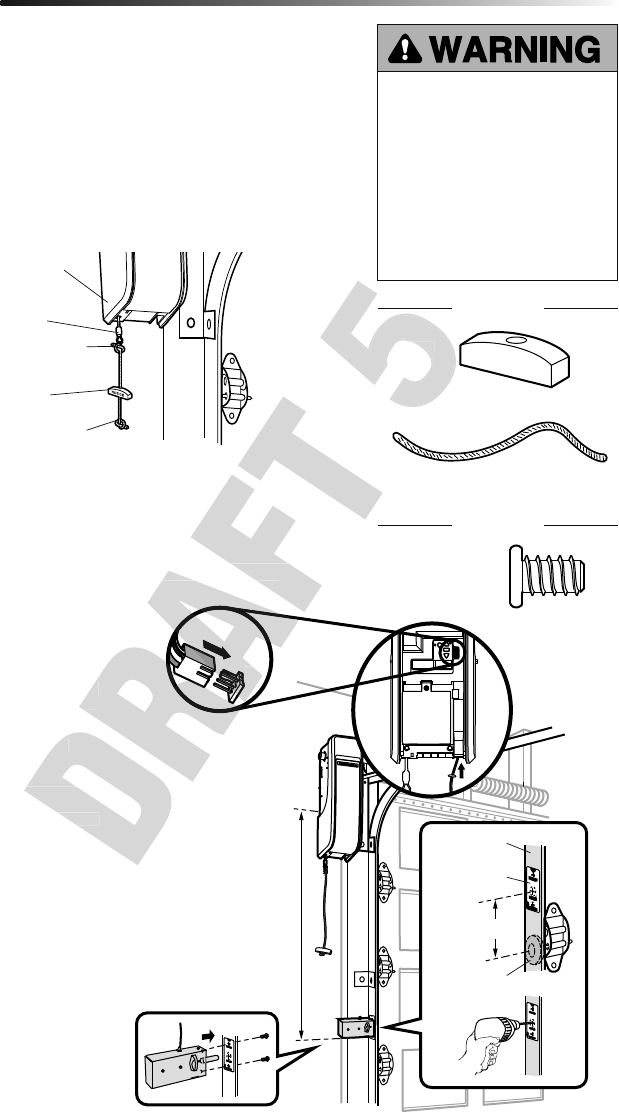
Attach the Emergency Release Rope and Handle
Install the Automatic Door Lock
2
3
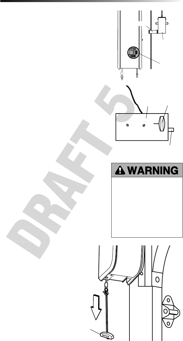
1. Insert one end of the emergency release rope through the handle. Make sure that
“NOTICE” is right side up. Secure with an overhand knot at least 1" (2.5 cm) from
the end of the rope to prevent slipping.
2. Insert the other end of the emergency release rope through the hole in the trolley
release arm. Mount the emergency release within reach, but at least 6 feet (1.83 m)
above fl oor, avoiding contact with vehicles to prevent accidental release and secure
with an overhand knot.
NOTE: If it is necessary to cut the rope, heat seal the cut end with a match or lighter to
prevent unraveling.
Installation
The automatic door lock (model 841LM) is used to prevent the door from being
manually opened once the door is fully closed, see Accessories page 36
Garage Door
Opener
Emergency
Release Cable
Overhand
Knot
Overhand
Knot
Emergency
Release Handle
To prevent possible SERIOUS INJURY
or DEATH from a falling garage door:
• If possible, use emergency release
handle to disengage door ONLY when
garage door is CLOSED. Weak or
broken springs or unbalanced door
could result in an open door falling
rapidly and/or unexpectedly.
• NEVER use emergency release handle
unless garage doorway is clear of
persons and obstructions.
HARDWARE
Screw 1/4"-
20x1/2" (2)
Rope
Handle
HARDWARE
10 feet (3.05 m)
max.
3" (7.6 cm)
Door Track
Roller
Lock
Template
1
2
3
4
5
6
NOTE: Older model 24 V door locks are
incompatible.
1. The lock must be mounted within
10 ft. (3.05m) of door opener If
possible, mount on same side as
door opener. The third roller from the
bottom is ideal for most installations.
2. Ensure rail surface is clean and attach
the lock template to the track so
that the bolt hole is approximately 3"
(7.6cm) from the center of a door
roller.
3. Drill holes as marked on the template.
4. Fasten automatic door lock to
the outside of the door track with
hardware provided.
5. Run bell wire up wall to door opener.
Use insulated staples to secure wire
in several places. Insert wire through
the bottom of the door opener.
6. Plug the connector into either plug in
the door opener.
A secondary door lock can be installed on
the opposite side of the door following the
instructions above.
Ensure rail surface is clean and attach
the lock template to the track so
that the bolt hole is approximately 3"
(7.6cm) from the center of a door
Drill holes as marked on the template.
door opener. The third roller from the
bottom is ideal for most installations.
manually opened once the door is fully closed, see Accessories page 36
6
The automatic door lock (model 841LM) is used to prevent the door from being
manually opened once the door is fully closed, see Accessories page 36
Handle
Handle
11
HARDWARE
Attach the Cable Tension Monitor (Required)
4
Drum
Cable
To insert or
release wire,
push in tab with
screwdriver tip
(to cable tension monitor)
(to garage door opener)
WHT/
GRN
Wall
2"-6"
(5-15 cm)
Approx. 3/4" (19 mm)
Cable
Tension
Monitor
Cable Tension
Monitor Roller
1/8"-1/4"
(3-6 mm)
Installation
The cable tension monitor MUST be
connected and properly installed before
the garage door opener will move in the
down direction.
The cable tension monitor detects ANY
slack that may occur in the cables and
will reverse the door, eliminating service
calls.
SIDE VIEW
Screws
#8-32x1" (2)
Drum
Cable Tension
Monitor Roller
Screw
14-10x2" (2)
NOTE: The cable tension monitor is shipped for left side installation. It is recommended
that the cable tension monitor be installed on the same side of the door as the door
opener. For right side installation, remove the snap-ring holding the roller in place and
reassemble it on the opposite side of the cable tension monitor.
1. Make sure the door cable is approximately 3/4" (19 mm) from the mounting surface.
Door adjustments or shimming may be required to achieve proper depth for the door
cable.
2. Position the cable tension monitor so the roller is 2"-6" from the drum and the roller
extends 1/8"-1/4" past the cable. Make sure cable tension monitor is located over a
wood support member and the roller is free from any obstructions.
NOTE: There must be no obstructions in the installation area that prevent the cable
tension monitor from closing completely when slack is detected.
3. Mark and drill 3/16" pilot holes for screws (pilot holes are not required for anchors).
4. Attach the cable tension monitor to the wall using the hardware provided. Make sure
that the roller is on top of the cable.
5. Run bell wire to door opener. Use insulated staples to secure wire.
6. Connect bell wire to the green quick-connect terminals on the door opener (polarity
is not important).
NOTE: Cable must have tension through entire door travel. Make sure there is no
slack in cable on opposite side of door during normal operation. If slack occurs
during door travel, adjust cables as required.
A second cable tension monitor may be installed for additional security. When two cable
tension monitors are installed, the door will not move in the down direction or will reverse
if one of the monitors detects slack or is disconnected.
If one of the cable tension monitors is removed, unplug both monitors from the opener.
Then plug in the monitor you wish to use and unplug and plug in the opener three times
to relearn the monitor to the opener.
WHT/
GRN
Cable
Drum
opener)
If one of the cable tension monitors is removed, unplug both monitors from the opener.
Then plug in the monitor you wish to use and unplug and plug in the opener three times
slack in cable on opposite side of door during normal operation. If slack occurs
A second cable tension monitor may be installed for additional security. When two cable
tension monitors are installed, the door will not move in the down direction or will reverse
If one of the cable tension monitors is removed, unplug both monitors from the opener.
Then plug in the monitor you wish to use and unplug and plug in the opener three times
Attach the cable tension monitor to the wall using the hardware provided. Make sure
Connect bell wire to the green quick-connect terminals on the door opener (polarity
Attach the cable tension monitor to the wall using the hardware provided. Make sure
Connect bell wire to the green quick-connect terminals on the door opener (polarity
12
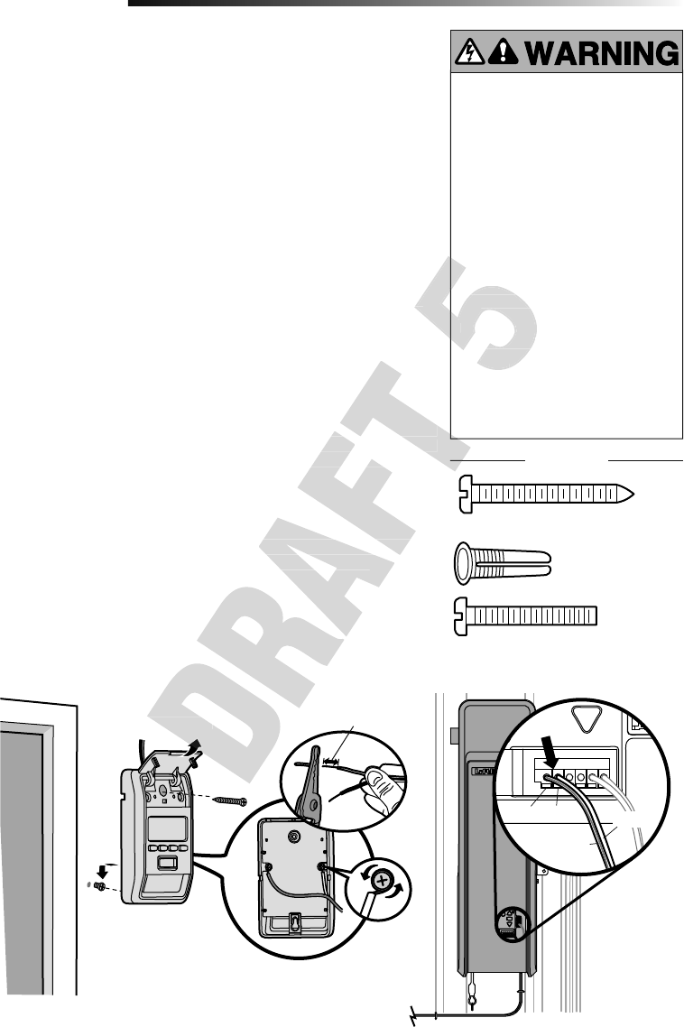
Install door control within sight of garage door, out of reach of small children at a
minimum height of 5 feet (1.5 m) above fl oors, landings, steps or any other adjacent
walking surface, and away from ALL moving parts of door.
Your garage door opener is compatible with up to 2 Smart Control Panels or 4 of any
other Security+ 2.0® door controls. NOTE: Older LiftMaster door controls and third party
products are not compatible.
For gang box installations it is not necessary to drill holes or install the drywall anchors.
Use the existing holes in the gang box.
1. Strip 7/16" (11 mm) of insulation from one end of the wire and separate the wires.
2. Connect one wire to each of the two screws on the back of the door control. The
wires can be connected to either screw. PRE-WIRED INSTALLATIONS: Choose
any two wires to connect, but make note of which wires are used.
3. Mark the location of the bottom mounting hole and drill a 5/32" (4 mm) hole.
4. Install the bottom screw, allowing 1/8" (3 mm) to protrude from the wall.
5. Position the bottom hole of the door control over the screw and slide down into
place.
6. Lift the push bar up and mark the top hole.
7. Remove the door control from the wall and drill a 5/32" (4 mm) hole for the top
screw.
8. Position the bottom hole of the door control over the screw and slide down into
place. Attach the top screw.
9. Run the white and red/white wire from the door control to the garage door opener.
Attach the wire to the wall and ceiling with the staples (not applicable for gang box
or pre-wired installations). Do not pierce the wire with the staple as this may cause
a short or an open circuit.
10. Connect the wire to the red and white terminals on the garage door opener. The
wires can be connected to either terminal.
11. Fasten the warning placard to the wall next to the door control.
NOTE: DO NOT connect the power and operate the garage door opener at this time. The
door will travel to the full open position but will not return to the close position until the
safety reversing sensors are connected and properly aligned. See page 14.
Install the Door Control (Smart Control Panel)
5
Installation
To prevent possible SERIOUS INJURY or
DEATH from electrocution:
• Be sure power is NOT connected
BEFORE installing door control.
• Connect ONLY to 7-28 VOLT low
voltage wires.
To prevent possible SERIOUS INJURY or
DEATH from a closing garage door:
• Install door control within sight of
garage door, out of reach of small
children at a minimum height of 5 feet
(1.5 m) above fl oors, landings, steps
or any other adjacent walking surface,
and away from ALL moving parts of
door.
• NEVER permit children to operate or
play with door control push buttons or
remote control transmitters.
• Activate door ONLY when it can be
seen clearly, is properly adjusted,
and there are no obstructions to door
travel.
• ALWAYS keep garage door in sight
until completely closed. NEVER permit
anyone to cross path of closing garage
door.
HARDWARE
Red White
WHT/RED
WHT
To insert or
release wire,
push in tab with
screwdriver tip
7/16" (11 mm)
Screw 6ABx1-1/4" (Standard installation) (2)
Screw 6-32x1"
(pre-wired) (2)
Drywall
Anchors (2)
Insulated Staples
(Not shown)
(to garage door opener)
(to door control)
garage door opener)
Fasten the warning placard to the wall next to the door control.
DO NOT connect the power and operate the garage door opener at this time. The
door will travel to the full open position but will not return to the close position until the
safety reversing sensors are connected and properly aligned. See page 14.
Run the white and red/white wire from the door control to the garage door opener.
Attach the wire to the wall and ceiling with the staples (not applicable for gang box
or pre-wired installations). Do not pierce the wire with the staple as this may cause
Connect the wire to the red and white terminals on the garage door opener. The
DO NOT connect the power and operate the garage door opener at this time. The
door will travel to the full open position but will not return to the close position until the
Remove the door control from the wall and drill a 5/32" (4 mm) hole for the top
Position the bottom hole of the door control over the screw and slide down into
Run the white and red/white wire from the door control to the garage door opener.
Attach the wire to the wall and ceiling with the staples (not applicable for gang box
or pre-wired installations). Do not pierce the wire with the staple as this may cause
• NEVER permit children to operate or
play with door control push buttons or
remote control transmitters.
• Activate door ONLY when it can be
Position the bottom hole of the door control over the screw and slide down into
seen clearly, is properly adjusted,
and there are no obstructions to door
travel.
remote control transmitters.
• Activate door ONLY when it can be
Position the bottom hole of the door control over the screw and slide down into
• NEVER permit children to operate or
play with door control push buttons or
remote control transmitters.
• Activate door ONLY when it can be
seen clearly, is properly adjusted,
and there are no obstructions to door
travel.
13
Screws
Light Lens
Drywall
Anchors
6-1/8" (15.6 cm)
Cord Retainer
Channel
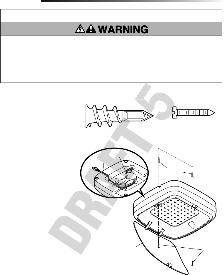
The MyQ LED Remote Light is designed to
plug directly into a standard 120V outlet.
Select an appropriate location on the
ceiling or wall to mount the light within 6
feet (1.83 m) of an electrical outlet so that
the cord and light are away from moving
parts.
NOTE: If installing light on drywall and a
ceiling joist cannot be located, use drywall
anchors provided. No pilot hole is required
for drywall anchors.
1. Drill pilot holes 6-1/8" (15.6 cm) apart
if mounting to joist.
OR
Screw in drywall anchors 6-1/8"
(15.6cm) apart if mounting to
drywall.
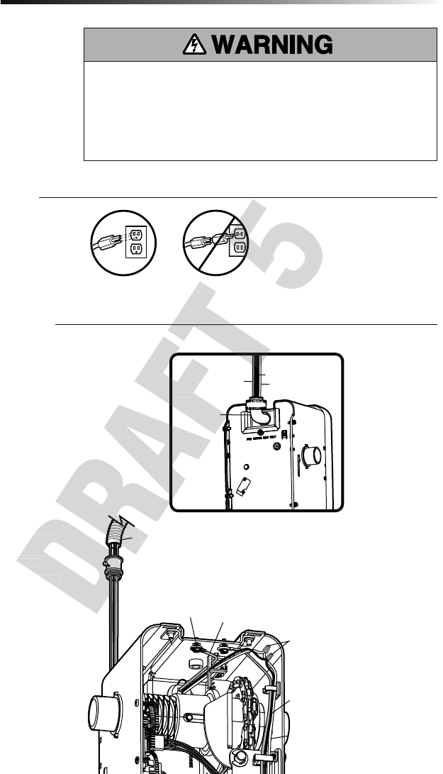
2. Determine the length of power cord
needed to reach the nearest outlet.
Wind any excess cord around cord
retainer on the top side of the light
base. Route the cord through the
channel so the light mounts fl ush.
3. Open the light lens.
4. Mount the light with the screws
provided.
5. Close the light lens.
6. Plug in the light to the outlet.
NOTE: The LED light is very bright.
DO NOT stare at the light while on a
ladder.
Your garage door opener remote light has
already been programmed at the factory to
operate with your opener. Any additional or
replacement remote lights will need to be
programmed.
Install MyQ® LED
Remote Light
6
Installation
IMPORTANT INSTALLATION INSTRUCTIONS
To reduce the risk of SEVERE INJURY or DEATH:
• This portable luminaire has a polarized plug (one blade
is wider than the other) as a feature to reduce the risk of
electric shock.
• This plug will fi t in a polarized outlet ONLY one way. If the
plug does not fi t fully in the outlet, reverse the plug. If it still
does not fi t, contact a qualifi ed electrician.
•. DO NOT alter the plug.
•. Light is intended for ceiling or wall mount and indoor
applications ONLY.
Drywall Anchor (screw-in) (2)
HARDWARE
Screw #6x1" (2)
Wind any excess cord around cord
retainer on the top side of the light
base. Route the cord through the
channel so the light mounts fl ush.
Determine the length of power cord
Cord Retainer
Channel
(screw-in) (2)
HARDWARE
HARDWARE
(screw-in) (2)
HARDWARE
HARDWARE
14
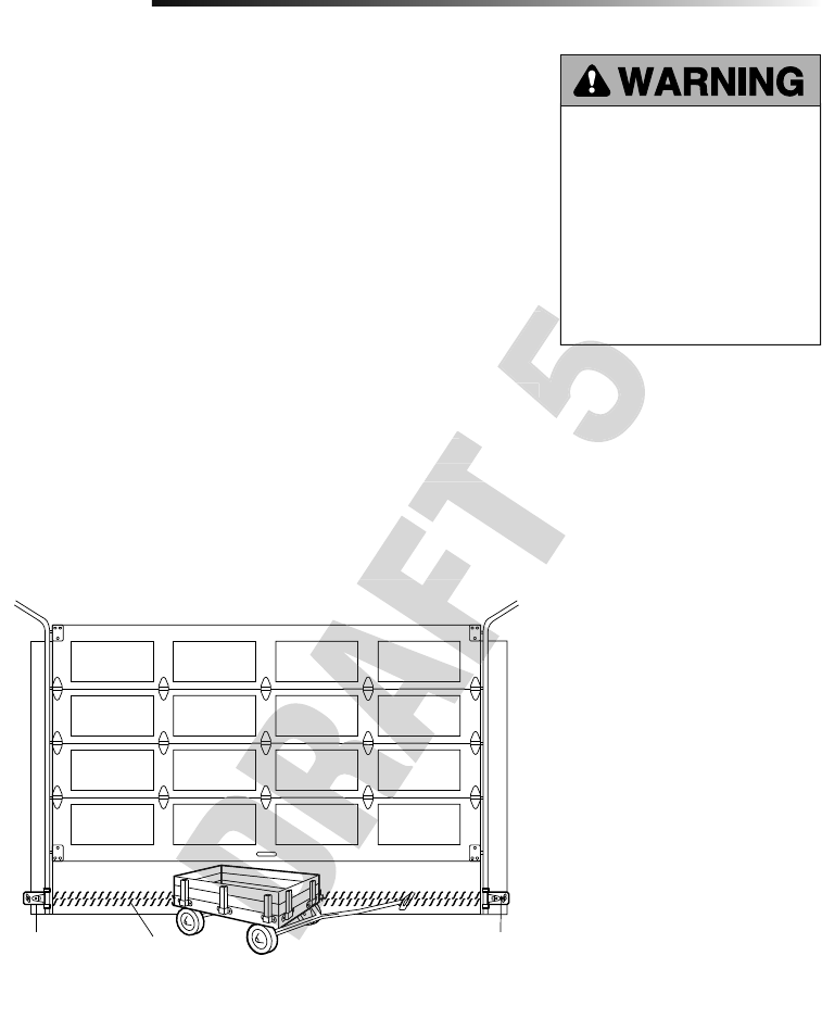
The safety reversing sensor must be connected and aligned correctly before the
garage door will move in the down direction. This is a required safety device and
cannot be disabled.
IMPORTANT INFORMATION ABOUT THE SAFETY REVERSING SENSOR
When properly connected and aligned, the safety reversing sensor will detect an obstacle
in the path of its electronic beam. The sending sensor (with an amber indicator light)
transmits an invisible light beam to the receiving sensor (with a green indicator light).
If an obstruction breaks the light beam while the door is closing, the door will stop and
reverse to full open position, and the opener lights will fl ash 10 times.
The sensors must be installed inside the garage so that the sending and receiving sensors
face each other across the door, no more than 6 inches (15 cm) above the fl oor. Either
can be installed on the left or right of the door as long as the sun never shines directly into
the receiving sensor lens.
The mounting brackets are designed to clip onto the track of sectional garage doors
without additional hardware.
If it is necessary to mount the sensors on the wall, the brackets must be securely fastened
to a solid surface such as the wall framing. Extension brackets (see accessories) are
available if needed. If installing in masonry construction, add a piece of wood at each
location to avoid drilling extra holes in masonry if repositioning is necessary.
The invisible light beam path must be unobstructed. No part of the garage door (door
tracks, springs, hinges, rollers or other hardware) may interrupt the beam while the door
is closing.
Be sure power is NOT connected to the
garage door opener BEFORE installing
the safety reversing sensor.
To prevent SERIOUS INJURY or
DEATH from a closing garage door:
• Correctly connect and align the
safety reversing sensor. This
required safety device MUST NOT
be disabled.
• Install the safety reversing sensor
so beam is NO HIGHER than 6" (15
cm) above garage fl oor.
Installation
Safety Reversing
Sensor
6" (15 cm) max.
above floor
Safety Reversing
Sensor
6" (15 cm) max.
above floor
Invisible Light
Beam Protection
Area
Install the Protector System®
7
Facing the door from inside the garage.
available if needed. If installing in masonry construction, add a piece of wood at each
location to avoid drilling extra holes in masonry if repositioning is necessary.
The invisible light beam path must be unobstructed. No part of the garage door (door
tracks, springs, hinges, rollers or other hardware) may interrupt the beam while the door
into
If it is necessary to mount the sensors on the wall, the brackets must be securely fastened
into
If it is necessary to mount the sensors on the wall, the brackets must be securely fastened
15
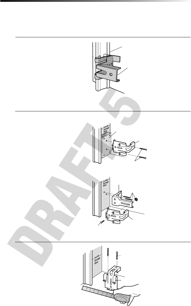
OPTION C: Floor Installation
1. Use wood blocks or extension
brackets (see Accessories) to elevate
sensor brackets so the lenses will be
no higher than 6" (15 cm) above the
fl oor.
2. Carefully measure and place right and
left assemblies at the same distance
out from the wall. Be sure all door
hardware obstructions are cleared.
3. Fasten to the fl oor with concrete
anchors as shown.
Installation
Fasten Wood Block to Wall with
Lag Screws (not provided)
Attach with Concrete Anchors
(not provided)
OPTION A: Track Installation
1. Slip the curved arms over the
rounded edge of each door track,
with the curved arms facing the door.
Snap into place against the side of the
track. It should lie fl ush, with the lip
hugging the back edge of the track, as
shown.
If your door track will not support the
bracket securely, wall installation is
recommended.
OPTION B: Wall Installation
1. Place the bracket against the wall
with curved arms facing the door. Be
sure there is enough clearance for the
sensor beam to be unobstructed.
2. If additional depth is needed, an
extension bracket (see Accessories)
or wood blocks can be used.
3. Use bracket mounting holes as a
template to locate and drill (2) 3/16"
diameter pilot holes on the wall at
each side of the door, no higher than
6" (15 cm) above the fl oor.
4. Attach brackets to wall with
lagscrews (notprovided).
If using extension brackets or wood blocks,
adjust right and left assemblies to the same
distance out from the mounting surface.
Make sure all door hardware obstructions
are cleared.
INSTALLING THE BRACKETS
Be sure power to the opener is disconnected. Install and align the brackets so the safety reversing sensors will face each other across
the garage door, with the beam no higher than 6" (15 cm) above the fl oor. Choose one of the following installations.
Door Track
Safety Reversing Sensor
Bracket
Safety Reversing Sensor Bracket
Lag Screws (not provided)
Safety Reversing Sensor Bracket
(Provided with Extension Bracket)
Extension Bracket (See Accessories)
Safety Reversing Sensor
Bracket
(Provided with
Extension Bracket)
OPTION C: Floor Installation
Use wood blocks or extension
brackets (see Accessories) to elevate
sensor brackets so the lenses will be
Make sure all door hardware obstructions
Fasten Wood
Fasten Wood
16
Installation
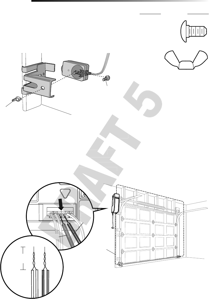
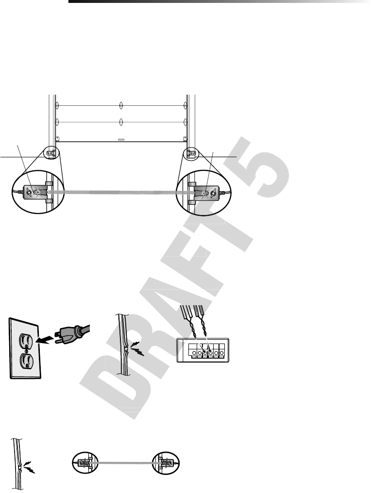
WIRE THE SAFETY REVERSING SENSORS
1. Run the wire from both sensors to the garage door opener. Attach the wire to the
wall and ceiling with the staples.
2. Strip 7/16 inch (11 mm) of insulation from each set of wires. Separate the wires.
Twist the white wires together. Twist the white/black wires together.
3. Insert the white wires into the white terminal on the garage door opener. Insert the
white/black wires into the grey terminal on the garage door opener. To insert or
remove the wires from the terminal, push in the tab with a screwdriver tip.
WHT/
BLK
WHT
Bell wire
MOUNTING THE SAFETY REVERSING SENSORS
1. Slide a 1/4"-20x1/2" carriage bolt head into the slot on each sensor.
2. Use wing nuts to fasten safety reversing sensors to brackets, with lenses pointing
toward each other across the door. Be sure the lens is not obstructed by a bracket
extension.
3. Finger tighten the wing nuts.
HARDWARE
Carriage Bolt
Wing Nut
Wing Nut
1/4"-20 (2)
Carriage Bolt
1/4"-20x1/2" (2)
7/16
(11 mm)
WHT
WHT/
BLK
white/black wires into the grey terminal on the garage door opener. To insert or
remove the wires from the terminal, push in the tab with a screwdriver tip.
Run the wire from both sensors to the garage door opener. Attach the wire to the
Strip 7/16 inch (11 mm) of insulation from each set of wires. Separate the wires.
Twist the white wires together. Twist the white/black wires together.
Insert the white wires into the white terminal on the garage door opener. Insert the
white/black wires into the grey terminal on the garage door opener. To insert or
remove the wires from the terminal, push in the tab with a screwdriver tip.
Run the wire from both sensors to the garage door opener. Attach the wire to the
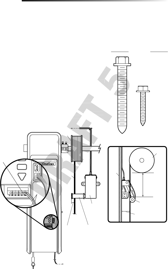
17
Connect Power
8
Installation
OPTION B: PERMANENT WIRING
CONNECTION
If permanent wiring is required by
your local code, refer to the following
procedure.
To make a permanent connection through
the 7/8 inch hole in the back of the garage
door opener (according to local code):
1. Be sure power is NOT connected to
the opener, and disconnect power to
circuit.
2. Remove the garage door opener from
the torsion bar, remove cover screws
and set the cover aside.
3. Cut the line cord 6" (15.2 cm) above
the strain relief.
4. Squeeze the strain relief and push
into motor unit, then remove the
strain relief from the line cord.
5. Install a 90° conduit (not provided)
or fl ex cable adapter (not provided)
to the 7/8" hole. Reinstall garage door
opener to torsion bar.
6. Run wires through conduit, cut to
proper length and strip installation.
7. Strip 1/2" (1.3 cm) of insulation from
the existing black, white and green
wires.
8. Connect the line to the black wire and
neutral to the white wire with wire
nuts (not provided). Connect ground
wire to the green ground screw.
9. Properly secure wires under plastic
ties so that they do not come into
contact with moving parts.
10. Reinstall cover.
To avoid installation diffi culties, do not
run the garage door opener at this time.
To reduce the risk of electric shock, your
garage door opener has a grounding type
plug with a third grounding pin. This plug
will only fi t into a grounding type outlet. If
the plug doesn’t fi
t into the outlet you have,
contact a qualifi ed electrician to install the
proper outlet.
There are two options for connecting
power:
OPTION A: TYPICAL WIRING
1. Plug in the garage door opener into a
grounded outlet.
2. DO NOT run garage door opener at
this time.
To prevent possible SERIOUS INJURY or DEATH from electrocution or fi re:
• Be sure power is NOT connected to the opener, and disconnect power to circuit
BEFORE removing cover to establish permanent wiring connection.
• Garage door installation and wiring MUST be in compliance with ALL local electrical
and building codes.
• NEVER use an extension cord, 2-wire adapter or change plug in ANY way to make it
fi t outlet. Be sure the opener is grounded.
RIGHT
WRONG
WRONGRIGHT
Green
Ground
Screw Ground Wire
Black Wire
Wire Nuts
(Not Provided
White Wire
Flexible
Conduit
90˚
Connector
(Not
Provided)
Green Wire White Wire
Black Wire
BACK VIEW
Squeeze the strain relief and push
into motor unit, then remove the
strain relief from the line cord.
Install a 90° conduit (not provided)
ex cable adapter (not provided)
the torsion bar, remove cover screws
Cut the line cord 6" (15.2 cm) above
Flexible
Conduit
(Not
Provided)
90˚
Connector
Provided)
Green Wire
WRONG
WRONG
18
Receiving Sensor
Green LED
Sending Sensor
Amber LED
Installation
IF THE AMBER LED ON THE SENDING SENSOR IS NOT GLOWING:
• Make sure there is power to the garage door opener.
• Make sure the sensor wire is not shorted/broken.
• Make sure the sensor has been wired correctly: white wires to white terminal and
white/black wires to grey terminal.
If the receiving sensor is in direct
sunlight, switch it with sending
sensor so it is on the opposite side
of the door.
(invisible light beam)
ENSURE THE SAFETY REVERSING SENSORS ARE ALIGNED
The door will not close if the sensors have not been installed and aligned correctly.
When the light beam is obstructed or misaligned while the door is closing, the door will
reverse and the garage door opener lights will fl ash ten times. If the door is already open,
it will not close. The sensors can be aligned by loosening the wing nuts, aligning the
sensors, and tightening the wing nuts.
1. Check to make sure the LEDs in both sensors are glowing steadily. The LEDs in both
sensors will glow steadily if they are aligned and wired correctly.
WHITE
GREY
IF THE GREEN LED ON THE RECEIVING SENSOR IS NOT GLOWING:
• Make sure the sensor wire is not shorted/broken.
• Make sure the sensors are aligned.
ENSURE THE DOOR CONTROL IS WIRED CORRECTLY
The yellow command LED and the red learn LED on the door control will blink quickly for
up to 5 minutes as the door control recharges. When the door control is operational, the
yellow command LED will glow steadily.
IF THE GREEN LED ON THE RECEIVING SENSOR IS NOT GLOWING:
• Make sure the sensor wire is not shorted/broken.
• Make sure the sensor has been wired correctly: white wires to white terminal and
IF THE AMBER LED ON THE SENDING SENSOR IS NOT GLOWING:
• Make sure the sensor has been wired correctly: white wires to white terminal and
Receiving Sensor
19
To reduce the risk of FIRE or INJURY
to persons:
• Disconnect ALL electric and battery
power BEFORE performing ANY
service or maintenance.
• Use ONLY LiftMaster part #485LM for
replacement battery.
• DO NOT dispose of battery in fi re.
Battery may explode. Check with local
codes for disposal instructions.
ALWAYS wear protective gloves and
eye protection when changing the
battery or working around the battery
compartment.
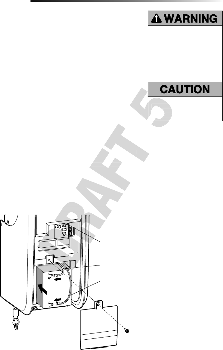
When in Battery Backup mode, MyQ® Smartphone Control and wireless MyQ devices
will be disabled. In battery backup mode, the automatic garage door lock will unlock
when the garage door is opened, and will remain disabled until power is restored.
1. Unplug the garage door opener.
2. Use a Phillips head screwdriver to remove the battery cover on the garage door
opener.
3. Partially insert the battery into the battery compartment with the terminals facing
out.
4. Connect red (+) and black (-) wires from the garage door opener to the
corresponding terminals on the battery.
5. Replace the battery cover.
6. Plug in the garage door opener.
BATTERY STATUS LED
GREEN LED:
All systems are normal.
• A solid green LED light indicates the battery is fully charged.
• A fl ashing green LED indicates the battery is being charged.
ORANGE LED:
The garage door opener has lost power and is in battery backup mode.
• A solid orange LED with beep, sounding approximately every 2 seconds, indicates
the garage door opener is operating on battery power.
• A fl ashing orange LED with beep, sounding every 30 seconds, indicates the battery
is low.
RED LED:
The garage door opener's 12V battery needs to be replaced.
• A solid red LED with beep, sounding every 30 seconds, indicates the 12V battery will
no longer hold a charge and needs to be replaced. Replace the battery back up to
maintain the battery backup feature.
NOTE: Battery does not have to be fully charged to operate the garage door opener.
Install the Battery Backup
9
Installation
Red wire (+)
Battery Status LED
Black wire (-)
Battery does not have to be fully charged to operate the garage door opener.
The garage door opener's 12V battery needs to be replaced.
• A solid red LED with beep, sounding every 30 seconds, indicates the 12V battery will
no longer hold a charge and needs to be replaced. Replace the battery back up to
Battery does not have to be fully charged to operate the garage door opener.
• A solid orange LED with beep, sounding approximately every 2 seconds, indicates
• A fl ashing orange LED with beep, sounding every 30 seconds, indicates the battery
• A solid red LED with beep, sounding every 30 seconds, indicates the 12V battery will
The garage door opener has lost power and is in battery backup mode.
• A solid orange LED with beep, sounding approximately every 2 seconds, indicates
ALWAYS wear protective gloves and
eye protection when changing the
battery or working around the battery
compartment.
ALWAYS wear protective gloves and
eye protection when changing the
battery or working around the battery
compartment.
20
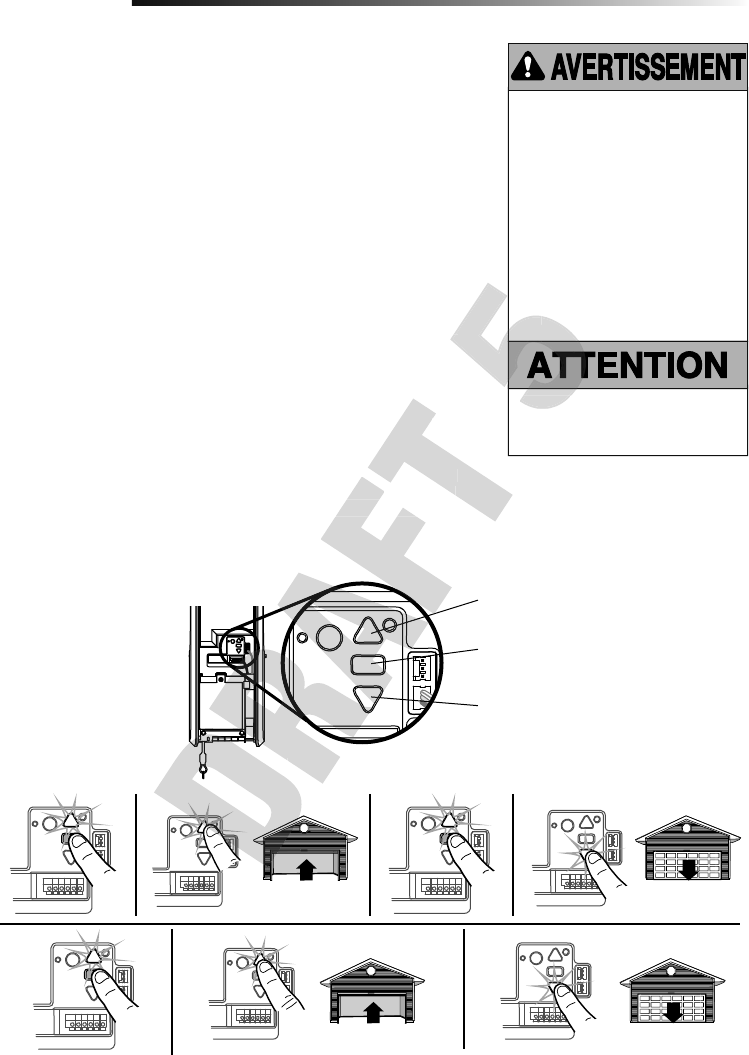
While programming, the UP and DOWN buttons can be used to move the door as needed.
1. Press and hold the Adjustment Button until the UP Button begins to fl ash and/or a
beep is heard.
2. Press and hold the UP Button until the door is in the desired UP position.
3. Once the door is in the desired UP position press and release the Adjustment Button.
The garage door opener lights will fl ash twice and the DOWN Button will begin to
fl ash.
4. Press and hold the DOWN Button until the door is in the desired DOWN position.
5. Once the door is in the desired DOWN position press and release the Adjustment
Button. The garage door opener lights will fl ash twice and the UP Button will begin
to fl ash.
6. Press and release the UP Button. When the door travels to the programmed UP
position, the DOWN Button will begin to fl ash.
7. Press and release the DOWN Button. The door will travel to the programmed DOWN
position. Programming is complete.
If the garage door opener lights are fl ashing 5 times during the steps for Program the
Travel, the programming has timed out. If the cable tension monitor is not installed or
is sensing too much slack in the cable, the garage door opener light will fl ash 5 times.
Ensure the cable tension monitor is correctly installed then follow the steps for Program
the Travel. If the garage door opener lights are fl ashing 10 times during the steps for
Program the Travel, the safety reversing sensors are misaligned or obstructed (refer
to page 18). When the sensors are aligned and unobstructed, cycle the door through a
complete up and down cycle using the remote control or the UP and DOWN buttons.
Programming is complete. If you are unable to operate the door up and down, repeat the
steps for Programming the Travel.
Travel limits regulate the points at which the door will stop when moving up or down.
Program the Travel
Adjustment
Without a properly installed safety
reversal system, persons (particularly
small children) could be SERIOUSLY
INJURED or KILLED by a closing
garage door.
• Incorrect adjustment of garage
door travel limits will interfere with
proper operation of safety reversal
system.
• After ANY adjustments are made,
the safety reversal system MUST
be tested. Door MUST reverse on
contact with 1-1/2" high (3.8 cm)
object (or 2x4 laid fl at) on fl oor.
1
1 2 3
5
4
6 7
PROGRAMMING BUTTONS
UP Button
Adjustment
Button
DOWN Button
To prevent damage to vehicles, be
sure fully open door provides adequate
clearance.
PROGRAMMING BUTTONS
ashing 10 times during the steps for
Program the Travel, the safety reversing sensors are misaligned or obstructed (refer
to page 18). When the sensors are aligned and unobstructed, cycle the door through a
complete up and down cycle using the remote control or the UP and DOWN buttons.
Programming is complete. If you are unable to operate the door up and down, repeat the
ashing 5 times during the steps for Program the
Travel, the programming has timed out. If the cable tension monitor is not installed or
is sensing too much slack in the cable, the garage door opener light will fl ash 5 times.
Ensure the cable tension monitor is correctly installed then follow the steps for Program
ashing 10 times during the steps for
Program the Travel, the safety reversing sensors are misaligned or obstructed (refer
To prevent damage to vehicles, be
Press and release the UP Button. When the door travels to the programmed UP
Press and release the DOWN Button. The door will travel to the programmed DOWN
object (or 2x4 laid fl
To prevent damage to vehicles, be
Press and release the UP Button. When the door travels to the programmed UP
Press and release the DOWN Button. The door will travel to the programmed DOWN
object (or 2x4 laid fl
21
TEST
1. With the door fully open, place a 1-1/2 inch (3.8 cm) board (or a 2x4 laid fl at) on the
fl oor, centered under the garage door.
2. Press the remote control push button to close the door. The door MUST reverse
when it makes contact with the board.
ADJUST
If the door stops but does not reverse:
1. Review the installation instructions provided to insure all steps were followed;
2. Repeat Program the Travel (see Adjustment Step 1);
3. Repeat the Safety Reversal test.
If the test continues to fail, call a trained door systems technician.
IMPORTANT SAFETY CHECK:
Test the Safety Reverse System after:
• Each adjustment of limits.
• Any repair to or adjustment of the door (including springs and hardware).
• Any repair to or buckling of the fl oor.
• Any repair to or adjustment of the garage door opener.
Test the Safety Reversal System
Test the Protector System®
1. Open the door. Place an obstruction in the path of the door.
2. Press the remote control push button to close the door. The door will not move
more than an inch (2.5 cm), and the garage door opener lights will fl ash 10 times.
The garage door opener will not close from a remote control if the LED in either
safety reversing sensor is off (alerting you to the fact that the sensor is misaligned or
obstructed).
If the garage door opener closes the door when the safety reversing sensor is
obstructed (and the sensors are no more than 6 inches [15 cm] above the fl oor), call
for a trained door systems technician.
Without a properly installed safety
reversal system, persons (particularly
small children) could be SERIOUSLY
INJURED or KILLED by a closing
garage door.
• Safety reversal system MUST be
tested every month.
• After ANY adjustments are made,
the safety reversal system MUST
be tested. Door MUST reverse on
contact with 1-1/2" (3.8 cm) high
object (or 2x4 laid fl at) on the fl oor.
Without a properly installed safety
reversing sensor, persons (particularly
small children) could be SERIOUSLY
INJURED or KILLED by a closing
garage door.
2
3
Adjustment
Safety Reversing Sensor Safety Reversing Sensor
1-1/2" (3.8 cm) board
(or a 2x4 laid flat)
Press the remote control push button to close the door. The door will not move
more than an inch (2.5 cm), and the garage door opener lights will fl
The garage door opener will not close from a remote control if the LED in either
safety reversing sensor is off (alerting you to the fact that the sensor is misaligned or
If the garage door opener closes the door when the safety reversing sensor is
obstructed (and the sensors are no more than 6 inches [15 cm] above the fl
Test the Protector System
®
Open the door. Place an obstruction in the path of the door.
Press the remote control push button to close the door. The door will not move
more than an inch (2.5 cm), and the garage door opener lights will fl
The garage door opener will not close from a remote control if the LED in either
22
1. With the door fully closed, push on the front of the cable tension monitor. A click
should be heard. If there is no click, the roller may be hitting the jamb and not
allowing the switch to detect slack in the cable. Make sure the cable tension monitor
is mounted fl ush with the wall and the roller is free from any obstructions.
If your cable tension monitor has been activated the UP and DOWN arrows will fl ash
diagnostic code 3-5, see page 31.
Test Cable Tension Monitor
Test Automatic Door Lock
To Open the Door Manually
4
5
6
Adjustment
To prevent possible SERIOUS INJURY
or DEATH from a falling garage door:
• If possible, use emergency release
handle to disengage door ONLY when
garage door is CLOSED. Weak or
broken springs or unbalanced door
could result in an open door falling
rapidly and/or unexpectedly.
• NEVER use emergency release handle
unless garage doorway is clear of
persons and obstructions.
Automatic
Door
Lock
Manual
Release
Lock Bolt “Locked”
Emergency
Release Handle
UP and
DOWN
arrows
Cable Tension
Monitor
Roller
Disengage any door locks before proceeding. The door should be fully closed if possible.
Pull down on the emergency release handle until a click noise is heard from the door
opener and lift the door manually.
To reconnect the door to the door opener, pull the emergency release handle straight
down a second time until a click noise is heard from the door opener. The door will
reconnect on the next UP or DOWN operation.
TEST THE EMERGENCY RELEASE:
1. Make sure the door is closed.
2. Pull the emergency release handle. The door should then be able to be opened
manually.
3. Return the door to the closed position.
4. Pull the emergency handle a second time.
5. Reconnect the door to the door opener.
1. With the door fully closed, the automatic door lock bolt should be protruding
through the track.
2. Operate the door in the open direction. The automatic door lock should retract before
the door begins to move.
3. Operate the door in the down direction. When the door reaches the fully closed
position, the automatic door lock should move into lock position to secure the door.
NOTE: If the automatic door lock does not function, the lock can be manually
released by sliding the manual release handle to the open position.
Pull the emergency release handle. The door should then be able to be opened
Return the door to the closed position.
Pull the emergency handle a second time.
Reconnect the door to the door opener.
To reconnect the door to the door opener, pull the emergency release handle straight
down a second time until a click noise is heard from the door opener. The door will
reconnect on the next UP or DOWN operation.
TEST THE EMERGENCY RELEASE:
Pull the emergency release handle. The door should then be able to be opened
Disengage any door locks before proceeding. The door should be fully closed if possible.
Pull down on the emergency release handle until a click noise is heard from the door
To reconnect the door to the door opener, pull the emergency release handle straight
down a second time until a click noise is heard from the door opener. The door will
Disengage any door locks before proceeding. The door should be fully closed if possible.
Pull down on the emergency release handle until a click noise is heard from the door
Operate the door in the down direction. When the door reaches the fully closed
position, the automatic door lock should move into lock position to secure the door.
If the automatic door lock does not function, the lock can be manually
released by sliding the manual release handle to the open position.
Operate the door in the open direction. The automatic door lock should retract before
Operate the door in the open direction. The automatic door lock should retract before

23
Operation
IMPORTANT SAFETY INSTRUCTIONS
To reduce the risk of SEVERE INJURY
or DEATH:
1. Read and follow all warnings and instructions.
2. ALWAYS keep remote controls out of reach of children.
NEVER permit children to operate or play with garage
door control push buttons or remote controls.
3. ONLY activate garage door when it can be seen clearly,
it is properly adjusted, and there are no obstructions to
door travel.
4. ALWAYS keep garage door in sight and away from
people and objects until completely closed. NO ONE
SHOULD CROSS THE PATH OF THE MOVING DOOR.
5. NO ONE SHOULD GO UNDER A STOPPED, PARTIALLY
OPENED DOOR.
6. If possible, use emergency release handle to disengage
trolley ONLY when garage door is CLOSED. Use caution
when using this release with the door open. Weak or
broken springs or unbalanced door could result in
an open door falling rapidly and/or unexpectedly and
increasing the risk of SEVERE INJURY or DEATH.
7. NEVER use emergency release handle unless garage
doorway is clear of persons and obstructions.
8. NEVER use emergency release handle to pull garage
door open or closed. If rope knot becomes untied, you
could fall.
9. After ANY adjustments are made, the safety reversal
system MUST be tested.
10. Safety reversal system MUST be tested every month.
Garage door MUST reverse on contact with 1-1/2" high
(3.8 cm) object (or a 2x4 laid fl at) on the fl oor. Failure
to adjust the garage door opener properly increases the
risk of SEVERE INJURY or DEATH.
11. ALWAYS KEEP GARAGE DOOR PROPERLY BALANCED.
An improperly balanced door may NOT reverse when
required and could result in SEVERE INJURY or DEATH.
12. ALL repairs to cables, spring assemblies and other
hardware, ALL of which are under EXTREME tension,
MUST be made by a trained door systems technician.
13. ALWAYS disconnect electric power to garage door
opener BEFORE making ANY repairs or removing covers.
14. This garage door opener system is equipped with an
unattended operation feature. The door could move
unexpectedly. NO ONE SHOULD CROSS THE PATH OF
THE MOVING DOOR.
15.
SAVE THESE
INSTRUCTIONS.
door open or closed. If rope knot becomes untied, you
7. NEVER use emergency release handle unless garage
THE MOVING DOOR.
15.
INSTRUCTIONS.
12. ALL repairs to cables, spring assemblies and other
hardware, ALL of which are under EXTREME tension,
MUST be made by a trained door systems technician.
13. ALWAYS disconnect electric power to garage door
opener BEFORE making ANY repairs or removing covers.
14. This garage door opener system is equipped with an
unattended operation feature. The door could move
unexpectedly. NO ONE SHOULD CROSS THE PATH OF
THE MOVING DOOR.
(3.8 cm) object (or a 2x4 laid fl
to adjust the garage door opener properly increases the
risk of SEVERE INJURY or DEATH.
11. ALWAYS KEEP GARAGE DOOR PROPERLY BALANCED.
An improperly balanced door may NOT reverse when
required and could result in SEVERE INJURY or DEATH.
12. ALL repairs to cables, spring assemblies and other
hardware, ALL of which are under EXTREME tension,
(3.8 cm) object (or a 2x4 laid fl
to adjust the garage door opener properly increases the
risk of SEVERE INJURY or DEATH.
11. ALWAYS KEEP GARAGE DOOR PROPERLY BALANCED.
An improperly balanced door may NOT reverse when
11. ALWAYS KEEP GARAGE DOOR PROPERLY BALANCED.
An improperly balanced door may NOT reverse when
required and could result in SEVERE INJURY or DEATH.
12. ALL repairs to cables, spring assemblies and other
hardware, ALL of which are under EXTREME tension,
24
FEATURES
Your garage door opener is equipped with
features to provide you with greater control
over your garage door operation.
Alert2Close
The Alert2Close feature provides a visual
and an audible alert that an unattended
door is closing.
TIMER-TO-CLOSE (TTC)
The TTC feature automatically closes the
door after a specifi ed time period that can
be adjusted using a TTC enabled door
control (Models 881LMW or 880LMW).
Prior to and during the door closing the
garage door opener lights will fl ash and the
garage door opener will beep.
MyQ®
MyQ allows you to control your garage
door opener from your mobile device or
computer from anywhere. MyQ technology
uses a 900Mhz signal to provide two way
communication between the garage door
opener and MyQ enabled accessories.
The garage door opener has an internal
gateway that allows the garage door
opener to communicate directly with a
home Wi-Fi® network and access your MyQ
account.
Using Your Garage Door Opener
THE PROTECTOR SYSTEM® (SAFETY
REVERSING SENSORS)
When properly connected and aligned,
the safety reversing sensors will detect
an obstruction in the path of the infrared
beam. If an obstruction breaks the infrared
beam while the door is closing, the door
will stop and reverse to full open position,
and the opener lights will fl ash 10 times.
If the door is fully open, and the safety
reversing sensors are not installed, or are
misaligned, the door will not close from
a remote control. However, you can close
the door if you hold the button on the door
control or keyless entry until the door is
fully closed. The safety reversing sensors
do not affect the opening cycle. For more
information see page 21.
ENERGY CONSERVATION
For energy effi ciency the garage door
opener will enter sleep mode when the
door is fully closed. The sleep mode
shuts the garage door opener down until
activated. The sleep mode is sequenced
with the garage door opener light; as the
light turns off the sensor LEDs will turn
off and whenever the garage door opener
lights turn on the sensor LEDs will light.
The garage door opener will not go into the
sleep mode until the garage door opener
has completed 5 cycles upon power up.
LIGHTS
The garage door opener light will turn on
when the opener is initially plugged in;
power is restored after interruption, or
when the garage door opener is activated.
The light will turn off automatically after
4-1/2 minutes.
Light Feature
The garage door opener is equipped with
an added feature; the lights will turn on
when someone enters through the open
garage door and the safety reversing
sensor infrared beam is broken. For added
control over the light on your garage door
opener, see page 27.
USING YOUR GARAGE DOOR
OPENER
The garage door opener can be activated
through a wall-mounted door control,
remote control, wireless keyless entry or
MyQ® accessory. When the door is closed
and the garage door opener is activated
the door will open. If the door senses an
obstruction or is interrupted while opening
the door will stop. When the door is in any
position other than closed and the garage
door opener is activated the door will
close. If the garage door opener senses
an obstruction while closing, the door will
reverse. If the obstruction interrupts the
sensor beam the garage door opener lights
will blink 10 times. However, you can close
the door if you hold the button on the door
control or keyless entry until the door is
fully closed. The safety reversing sensors
do not affect the opening cycle. The safety
reversing sensor must be connected and
aligned correctly before the garage door
opener will move in the down direction.
BATTERY BACKUP
The battery backup system allows access
in and out of your garage, even when the
power is out. When the garage door opener
is operating on battery power, the garage
door opener will run slower, the light will
not function, the Battery Status LED will
glow solid orange, and a beep will sound
approximately every 2 seconds.
Operation
MEMORY CAPACITY
SECURITY+ 2.0® ACCESSORIES MEMORY CAPACITY
Remote Controls Up to 40
Door Controls Up to 2 Smart Control Panels or 4 of any other
Security+ 2.0® door controls
Keyless Entries Up to 4
MyQ® Acccessories Up to 16
Up to 4
Up to 16
Up to 40
Up to 2 Smart Control Panels or 4 of any other
Security+ 2.0
door controls
has completed 5 cycles upon power up.
MEMORY CAPACITY
Up to 2 Smart Control Panels or 4 of any other
with the garage door opener light; as the
light turns off the sensor LEDs will turn
off and whenever the garage door opener
lights turn on the sensor LEDs will light.
The garage door opener will not go into the
sleep mode until the garage door opener
has completed 5 cycles upon power up.
ciency the garage door
opener will enter sleep mode when the
door is fully closed. The sleep mode
shuts the garage door opener down until
activated. The sleep mode is sequenced
with the garage door opener light; as the
light turns off the sensor LEDs will turn
off and whenever the garage door opener
the door will stop. When the door is in any
position other than closed and the garage
the door if you hold the button on the door
fully closed. The safety reversing sensors
do not affect the opening cycle. For more
opener, see page 27.
USING YOUR GARAGE DOOR
OPENER
The garage door opener can be activated
through a wall-mounted door control,
remote control, wireless keyless entry or
the door if you hold the button on the door
fully closed. The safety reversing sensors
do not affect the opening cycle. For more
opener, see page 27.
USING YOUR GARAGE DOOR
OPENER
The garage door opener can be activated
through a wall-mounted door control,
remote control, wireless keyless entry or
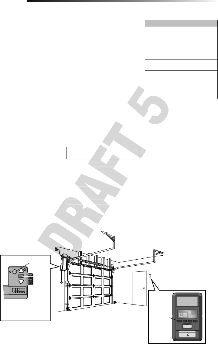
25
LED Definition
Blue Off - Wi-Fi is not turned on.
Blinking - Garage door
opener is in Wi-Fi learn
mode.
Solid - Mobile device
connected to the garage
door opener.
Blue and
Green Blinking - Attempting to
connect to router.
Green Blinking - Attempting to
connect to the Internet
server.
Solid - Wi-Fi has been set
up and garage door opener
is connected to the Internet.
NOTES:
The MyQ® Smartphone Control WILL NOT
work if the garage door opener is operating
on battery power.
To erase the Wi-Fi settings, see page 29.
If you need help adding devices to your
MyQ account, or to learn more go to
WiFiHelp.LiftMaster.com.
Operation
The Wi-Fi® Garage Door Opener is
compatible with up to 16 MyQ enabled
accessories. Up to 10 devices can be
paired to the Wi-Fi garage door opener’s
internal gateway. These devices can be
controlled with the MyQ app. These devices
include any combination of MyQ garage
door openers, Wi-Fi garage door openers,
MyQ light controls, MyQ gate operators
or MyQ commercial door operators. A
LiftMaster Internet Gateway (828LM)
can be added if you need to control more
than 10 devices using the MyQ app. Up
to 6 devices can be paired to garage
door opener itself (controlled by garage
door opener through 900MHz). These
devices include any combination of MyQ
light controls or a garage door and gate
monitor.
You will need:
• Wi-Fi enabled smartphone, tablet or
laptop
• Broadband Internet Connection
• Wi-Fi signal in the garage (2.4 Ghz,
802.11b/g/n required), see page 4
• Password for your home network
(router's main account, not guest
network)
• MyQ® serial number located on the
garage door opener
SYNCHRONIZE THE DOOR CONTROL
To synchronize the door control to the
garage door opener, press the push bar
until the garage door opener activates (it
may take up to 3 presses).The garage door
opener must run through a complete cycle
before it will activate Wi-Fi® programming.
CONNECT YOUR GARAGE DOOR
OPENER TO YOUR HOME WI-FI
NETWORK
1. Use the Smart Control Panel®, go to
Menu > Program > Wi-Fi Setup OR
press and release the yellow LEARN
button on the garage door opener 3
times. The garage door opener will
beep once. You have 20 minutes to
complete the connection process.
2. On your mobile device, go to
Settings > Wi-Fi and select the
network with the “MyQ-” prefi x.
3. Launch the web browser on your
smartphone or tablet. Enter
setup.myqdevice.com into the
browser address bar. Follow the
on screen prompts to connect the
garage door opener to your Wi-Fi
network. The MyQ serial number will
display on screen.
Write the serial number in the space
below.
4. Download the MyQ app from the
App Store® or Google Play™ store.
Sign up for your MyQ account and
add the MyQ serial number to your
account.
To add a second Wi-Fi garage door opener,
repeat steps 1-3. Add the second MyQ
serial number to your account in the MyQ
app.
Navigation
Buttons
An LED on the garage door
opener will indicate Wi-Fi
status. See table above.
LED
Learn
Button
Connect With Your Smartphone
programming.
may take up to 3 presses).The garage door
opener must run through a complete cycle
repeat steps 1-3. Add the second MyQ
serial number to your account in the MyQ
app.
Sign up for your MyQ account and
add the MyQ serial number to your
account.
To add a second Wi-Fi garage door opener,
repeat steps 1-3. Add the second MyQ
serial number to your account in the MyQ
4. Download the MyQ app from the
®
or Google Play™ store.
Sign up for your MyQ account and
add the MyQ serial number to your
WiFiHelp.LiftMaster.com.
garage door opener to your Wi-Fi
network. The MyQ serial number will
Write the serial number in the space
NOTES:
The MyQ
®
The MyQ
Smartphone Control WILL NOT
®
work if the garage door opener is operating
on battery power.
into the
NOTES:
The MyQ
®
The MyQThe MyQ
Smartphone Control WILL NOT
work if the garage door opener is operating
on battery power.
3. Launch the web browser on your
into the
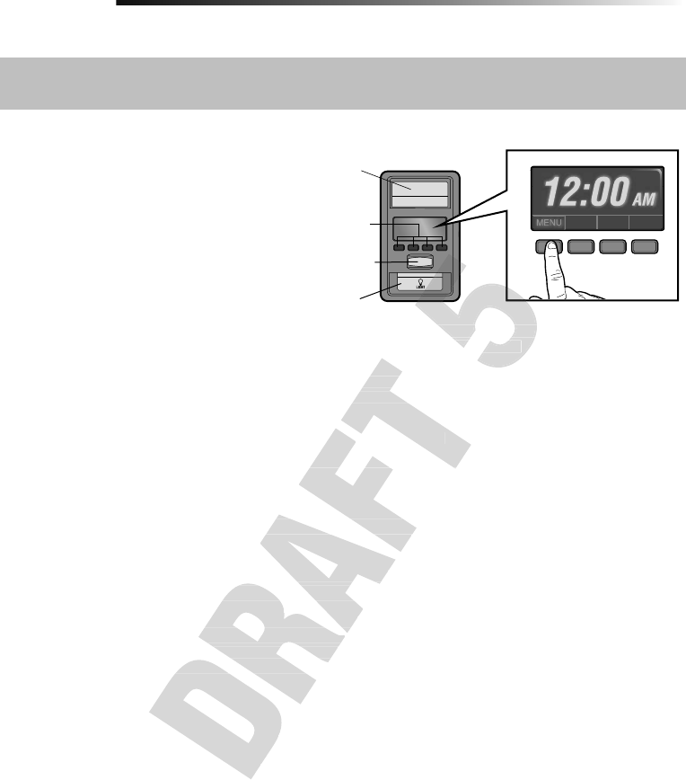
26
Operation
Using the Door Control
SYNCHRONIZE THE DOOR CONTROL
To synchronize the door control to the garage door opener, press the push bar until the garage door opener activates (it may take up to 3
presses). Test the door control by pressing the push bar, each press of the push bar will activate the garage door opener.
Up to 2 Smart Control Panels® or 4 of any other
Security+2.0® door controls can be connected to the
garage door opener.
PUSH BAR
Press the push bar to open or close the door.
NAVIGATION BUTTONS
Use the navigation buttons to make selections and
program features.
LIGHT BUTTON
Press the LIGHT button to turn the garage door opener
lights on or off. When the lights are turned on they will
stay on until the LIGHT button is pressed again, or until
the garage door opener is activated. Once the garage door opener is activated the lights will turn off after the specifi ed period of time (the
factory setting is 4-1/2 minutes). The LIGHT button will not control the lights when the door is in motion.
SCREEN
The screen will display the time and temperature until the menu button is pressed, and then it will display the menu options. If there is a
problem with the garage door opener the screen will display the Diagnostic Code. Refer to the Troubleshooting section.
The following features are accessible through the screen using the navigation buttons:
LEARN A DEVICE
Any compatible remote controls, wireless keyless entry, Wi-Fi garage door openers, or MyQ® accessories can be programmed to the
garage door opener by accessing the menu and using the navigation buttons.
LOCK
The LOCK feature is designed to prevent activation of the garage door opener from remote controls while still allowing activation from
the door control and keyless entry. This feature is useful for added peace of mind when the home is empty (i.e. vacation).
TIMER-TO-CLOSE (TTC)
DO NOT enable TTC if operating a one-piece door. TTC is to be used ONLY with sectional doors. Factory default is set to off. TTC can
be set to automatically close your garage door from the fully open position after a specifi ed period of time (1, 5, 10 minute intervals or
a custom setting up to 99 minutes). The garage door opener will beep and the lights will fl ash before closing the door. The screen on
the door control can display the status of the TTC. TTC WILL NOT work if the garage door opener is operating by battery power or if the
safety reversing sensors are misaligned. This feature is NOT intended to be the primary method of closing the door. A keyless entry
should be installed in the event of an accidental lock out when using this feature.
NOTE: Before enabling the TTC for the fi rst time, or if you experience a power outage, cycle the garage door opener open and closed to
allow the TTC to set.
AUTOMATIC LIGHT
Motion Sensor
Factory default is set to on. This feature automatically turns on the garage door opener lights when motion is sensed. The lights will
come on for the set period of time, then shut off. If using the garage door opener light as a work light disable the motion sensor,
otherwise the light will turn off automatically if you are beyond the range of the sensor.
Light Feature
The lights will turn on when someone enters through the open garage door and the safety reversing sensor infrared beam is broken.
MAINTENANCE ALERT (MAS)
This feature assists the homeowner in ensuring the garage door opener system stays in good working condition. When the garage door
opener needs to be serviced (approximately 4500 garage door opener cycles) the command (yellow) and service (red) LEDs will begin
to alternately fl ash back and forth. The factory setting for the MAS feature is off and can be activated at time of installation. Contact your
installing dealer for service.
Push Bar
LIGHT
button
Screen
Motion
Sensor
Navigation
Buttons
: Before enabling the TTC for the fi rst time, or if you experience a power outage, cycle the garage door opener open and closed to
Factory default is set to on. This feature automatically turns on the garage door opener lights when motion is sensed. The ligh
come on for the set period of time, then shut off. If using the garage door opener light as a work light disable the motion sen
otherwise the light will turn off automatically if you are beyond the range of the sensor.
be set to automatically close your garage door from the fully open position after a specifi
a custom setting up to 99 minutes). The garage door opener will beep and the lights will fl
the door control can display the status of the TTC. TTC WILL NOT work if the garage door opener is operating by battery power o
safety reversing sensors are misaligned. This feature is NOT intended to be the primary method of closing the door.
should be installed in the event of an accidental lock out when using this feature.
rst time, or if you experience a power outage, cycle the garage door opener open and closed to
The LOCK feature is designed to prevent activation of the garage door opener from remote controls while still allowing activati
the door control and keyless entry. This feature is useful for added peace of mind when the home is empty (i.e. vacation).
DO NOT enable TTC if operating a one-piece door. TTC is to be used ONLY with sectional doors. Factory default is set to off. TT
be set to automatically close your garage door from the fully open position after a specifi
a custom setting up to 99 minutes). The garage door opener will beep and the lights will fl
the door control can display the status of the TTC. TTC WILL NOT work if the garage door opener is operating by battery power o
safety reversing sensors are misaligned. This feature is NOT intended to be the primary method of closing the door.
The following features are accessible through the screen using the navigation buttons:
Any compatible remote controls, wireless keyless entry, Wi-Fi garage door openers, or MyQ
garage door opener by accessing the menu and using the navigation buttons.
The LOCK feature is designed to prevent activation of the garage door opener from remote controls while still allowing activati
the door control and keyless entry. This feature is useful for added peace of mind when the home is empty (i.e. vacation).
The screen will display the time and temperature until the menu button is pressed, and then it will display the menu options. I
problem with the garage door opener the screen will display the Diagnostic Code. Refer to the Troubleshooting section.
The following features are accessible through the screen using the navigation buttons:
Any compatible remote controls, wireless keyless entry, Wi-Fi garage door openers, or MyQ
the garage door opener is activated. Once the garage door opener is activated the lights will turn off after the specifi
factory setting is 4-1/2 minutes). The LIGHT button will not control the lights when the door is in motion.
the garage door opener is activated. Once the garage door opener is activated the lights will turn off after the specifi
factory setting is 4-1/2 minutes). The LIGHT button will not control the lights when the door is in motion.
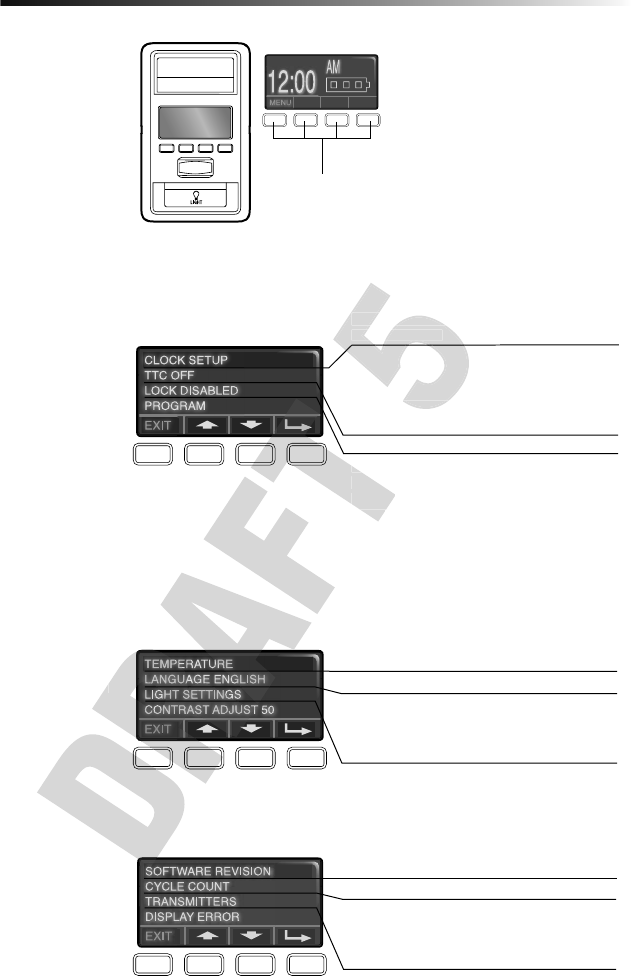
27
Operation
SETUP
The features on the door control can be
programmed through a series of menus on
the screen and the navigation buttons.
Refer to the descriptions below.
SCREEN
The main screen displays the time,
temperature, and current battery charge (if
applicable)
FEATURES
Press the navigation button below "MENU"
to view the Features menu.
SETTINGS
Press the navigation button below the
down arrow till you see TEMPERATURE to
view the Settings menu.
SERVICE
Press and hold the LIGHT button, then
press the second navigation button to view
the Service menu.
To program a remote control or keyless
entry to the garage door opener using the
door control, see page 28.
Navigation Buttons
Set the time, choose 12 or 24 hour clock and
show/hide clock.
For sectional doors ONLY. Set the
Timer-to-Close feature off/on and set the time
interval before door closes. NOTE: DO NOT
enable TTC if operating a one-piece door. TTC is
to be used ONLY with sectional doors.
Enable/disable lock.
Set up Wi-Fi*, add remote controls, MyQ®
devices, an extra remote button to control your
garage door opener lights, or a keyless entry.
* The garage door opener must run through a
complete cycle before it will activate Wi-Fi®
programming. For help related to Wi-Fi, visit
WiFiHelp.LiftMaster.com.
Display the temperature in Fahrenheit or Celsius
and show/hide the temperature.
Select a language.
Set duration for garage door opener light to
stay on after operation, selectable range of
1-1/2 to 4-1/2 minutes. Turn the Motion sensor
off/on, and turn the entry light feature off/on.
Adjust the contrast of the screen.
Displays software version information.
Turn the Maintenance Alert (MAS) on/off.
Displays the number of remote controls, MyQ®
devices, door controls and keyless entries
currently programmed to operate the garage
door opener.
Displays any errors that have occurred.
down arrow till you see TEMPERATURE to
Set up Wi-Fi*, add remote controls, MyQ
devices, an extra remote button to control your
garage door opener lights, or a keyless entry.
* The garage door opener must run through a
Set the time, choose 12 or 24 hour clock and
show/hide clock.
For sectional doors ONLY. Set the
Timer-to-Close feature off/on and set the time
interval before door closes.
enable TTC if operating a one-piece door. TTC is
Set the time, choose 12 or 24 hour clock and
show/hide clock.
For sectional doors ONLY. Set the
Timer-to-Close feature off/on and set the time
interval before door closes.
enable TTC if operating a one-piece door. TTC is
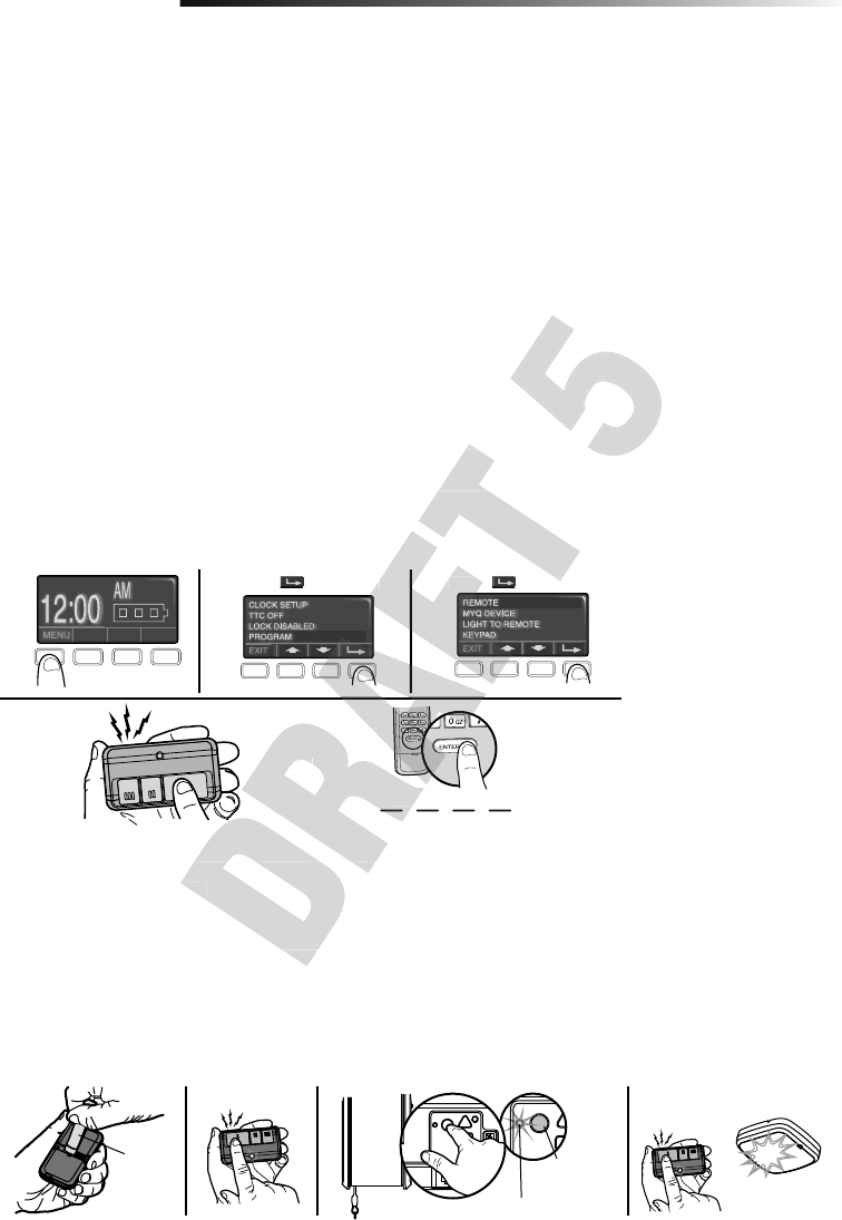
28
Programming
893MAX Remote Control
Your remote control has been programmed at the factory to operate with your garage
door opener. If the remote does not work or you would like to program additional
devices, follow the programming steps below.
Up to 40 Security+ 2.0® remote controls can be programmed to the garage door opener.
Older LiftMaster remote controls are NOT compatible, see page 36 for compatible
accessories. Programming can be done through the door control or the learn button
on the garage door opener. To program additional accessories refer to the instructions
provided with the accessory or visit LiftMaster.com. If your vehicle is equipped with a
Homelink®, you may require an external adapter depending on the make, model, and year
of your vehicle. Visit www.homelink.com for additional information.
TO ADD, REPROGRAM, OR CHANGE A 893MAX REMOTE CONTROL/877LM
KEYLESS ENTRY PIN USING THE DOOR CONTROL
1. Press the navigation button below "MENU" to view the Features menu.
2. Use the navigation buttons to scroll to "PROGRAM".
3. Select "REMOTE" or "KEYPAD" to program from the program menu.
4. Remote Control: Press the button on the remote control that you wish to operate
your garage door.
Keyless Entry: Enter a 4-digit personal identifi cation number (PIN) of your choice on
the keyless entry keypad. Then press the ENTER button.
The garage door opener lights will fl ash (or two clicks will be heard) when the code has
been programmed. Repeat the steps above for programming additional remote controls
or keyless entry devices. If programming is unsuccessful, program the remote using the
learn button.
123
OR
PIN
????
4
Press to continue. Press to continue.
PROGRAM A 893MAX REMOTE CONTROL USING THE LEARN BUTTON ON
THE GARAGE DOOR OPENER
1. Press and hold the program button on the remote control until the LED on the front
of the remote control turns on.
2. Press and release the remote control button you wish to use and then press any
other button to exit programming.
3. Press and release the Learn button on the garage door opener. The Learn LED will
light. Within 30 seconds...
4. Press the remote control button programmed in step 2 until the garage door opener
light fl ashes or two clicks are heard.
1 2 3 4
LEARN LED
LEARN
Button
“click”
“click”
Visor
Clip
To program other types of remote controls or keyless entries see the instructions included with the device or visit LiftMaster.com.
PROGRAM A 893MAX REMOTE CONTROL USING THE LEARN BUTTON ON
THE GARAGE DOOR OPENER
Press and hold the program button on the remote control until the LED on the front
Press and release the remote control button you wish to use and then press any
OR
????
PROGRAM A 893MAX REMOTE CONTROL USING THE LEARN BUTTON ON
to continue.
Press
Press
cation number (PIN) of your choice on
ash (or two clicks will be heard) when the code has
been programmed. Repeat the steps above for programming additional remote controls
or keyless entry devices. If programming is unsuccessful, program the remote using the
to continue.
Press the button on the remote control that you wish to operate
Press the button on the remote control that you wish to operate
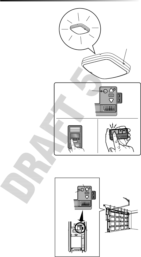
29
Programming
Program the MyQ® LED Remote Light
Your garage door opener remote light has already been
programmed at the factory to operate with your opener.
Any additional or replacement remote lights will need to be
programmed.
PROGRAM A DOOR OPENER TO THE MyQ LED REMOTE
LIGHT
1. Press the LEARN button on the light until the green LED
comes ON.
2. Press the LEARN button on the door opener. OR
On the Smart Control Panel® go to Menu > Program>
MyQDevice.
3. The code has been programmed when the remote light blinks
once.
PROGRAM A REMOTE CONTROL TO THE MyQ LED
REMOTE LIGHT
1. Press the LEARN button on the light until the LED comes ON.
2. Press the button on the remote control that you wish to
operate the light.
3. The code has been programmed when the remote light blinks
once.
To program the light with other accessories, refer to the manual
for your accessory.
ADD THE MyQ LED REMOTE LIGHT TO MyQ ACCOUNT
1. Press the LEARN button on the light until the LED comes ON.
2. Login to the MyQ app and add the MyQ LED Remote Light.
TO ERASE ALL PROGRAMMING FROM THE MyQ LED
REMOTE LIGHT
1. Press and hold the LEARN button until the LED turns off
(6-10 seconds). All programming is now erased.
LEARN
Button
Black Adjustment Button
To Erase the Memory
ERASE ALL REMOTE CONTROLS AND KEYLESS ENTRIES
1. Press and hold the LEARN button on garage door opener
until the learn LED goes out (approximately 6 seconds). All
remote control and keyless entry codes are now erased.
Reprogram any accessory you wish to use.
ERASE ALL DEVICES (Including MyQ enabled
accessories)
1. Press and hold the LEARN button on garage door opener
until the learn LED goes out (approximately 6 seconds).
2. Immediately press and hold the LEARN button again until the
learn LED goes out. All codes are now erased. Reprogram
any accessory you wish to use.
ERASE THE WI-FI NETWORK FROM THE GARAGE DOOR
OPENER
1. Press and hold the black adjustment button on the garage
door opener until 3 beeps are heard (Approximately 6
seconds).
ERASE A MyQ ACCOUNT
Go to myLiftMaster.com to delete your MyQ account. LEARN
Button
Smart Control Panel
Door Opener
LEARN Button
LEARN Button
ERASE ALL REMOTE CONTROLS AND KEYLESS ENTRIES
Press and hold the LEARN button on garage door opener
until the learn LED goes out (approximately 6 seconds). All
remote control and keyless entry codes are now erased.
Reprogram any accessory you wish to use.
ERASE ALL DEVICES (Including MyQ enabled
ERASE ALL REMOTE CONTROLS AND KEYLESS ENTRIES
Press and hold the LEARN button on garage door opener
until the learn LED goes out (approximately 6 seconds). All
TO ERASE ALL PROGRAMMING FROM THE MyQ LED
Press and hold the LEARN button until the LED turns off
ADD THE MyQ LED REMOTE LIGHT TO MyQ ACCOUNT
Press the LEARN button on the light until the LED comes ON.
Login to the MyQ app and add the MyQ LED Remote Light.
Smart Control Panel
Smart Control Panel
Door Opener
LEARN Button
Door Opener
LEARN Button

30
Maintenance
MAINTENANCE SCHEDULE
EVERY MONTH
• Manually operate door. If it is unbalanced or binding, call a trained door systems
technician.
• Check to be sure door opens and closes fully. Adjust limits if necessary (see
Adjustment Step 1).
• Repeat the safety reverse test. Make any necessary adjustments (see Adjustment
Step 2).
EVERY YEAR
• Oil door rollers, bearings and hinges. The garage door opener does not require
additional lubrication. Do not grease the door tracks.
EVERY TWO TO THREE YEARS
• Use a rag to wipe away the existing grease from the garage door opener rail. Reapply
a small layer of white lithium grease to the top and underside of the rail surface
where the trolley slides.
MyQ LED Remote Light
• Unplug the light before cleaning.
• Use a lightly dampened cloth for cleaning.
• DO NOT use liquid cleaners on the light lens.
Care of Your Garage Door Opener
To prevent possible SERIOUS INJURY
or DEATH:
• NEVER allow small children near
batteries.
• If battery is swallowed, immediately
notify doctor.
To reduce risk of fi re, explosion or
chemical burn:
• Replace ONLY with 3V CR2032
coin batteries.
• DO NOT recharge, disassemble,
heat above 212° F (100° C) or
incinerate.
THE REMOTE CONTROL BATTERY
The LED(s) on your remote control will stop fl ashing when the battery is low and needs to be
replaced. To replace battery, open the case as shown. Insert battery positive side up (+).
Replace the battery with only 3V CR2032 coin cell batteries. Dispose of old battery properly.
3V CR2032
Pry open the case fi rst
in the middle (1), then
at each side (2 and 3)
with the visor clip.
1
2
3
3V
ashing when the battery is low and needs to be
replaced. To replace battery, open the case as shown. Insert battery positive side up (+).
Replace the battery with only 3V CR2032 coin cell batteries. Dispose of old battery properly.
ashing when the battery is low and needs to be
replaced. To replace battery, open the case as shown. Insert battery positive side up (+).
• Use a rag to wipe away the existing grease from the garage door opener rail. Reapply
a small layer of white lithium grease to the top and underside of the rail surface
• Use a rag to wipe away the existing grease from the garage door opener rail. Reapply
a small layer of white lithium grease to the top and underside of the rail surface

31
Troubleshooting
Your garage door opener is programmed
with self-diagnostic capabilities. The UP
and DOWN arrows on the garage door
opener fl ash the diagnostic codes.
Diagnostic Chart UP Button
DOWN Button
DIAGNOSTIC CODE SYMPTOM SOLUTION
Up Arrow
Flash(es)
Down Arrow
Flash(es)
1 1 The garage door opener
will not close and the
light fl ashes.
Safety sensors are not installed, connected or wires may be cut. Inspect
sensor wires for a disconnected or cut wire.
1 2 The garage door opener
will not close and the
light fl ashes.
There is a short or reversed wire for the safety sensors. Inspect safety sensor
wire at all staple points and connection points and replace wire or correct as
needed.
1 3 The door control will not
function.
The wires for the door control are shorted or the door control is faulty.
Inspect door control wires at all staple points and connection points and
replace wire or correct as needed.
1 4 The garage door opener
will not close and the
light fl ashes.
Safety sensors are misaligned or were momentarily obstructed. Realign
both sensors to ensure both LEDs are steady and not fl ickering. Make sure
nothing is hanging or mounted on the door that would interrupt the sensors
path while closing.
1 5 Door moves 6-8"
(15-20cm) stops or
reverses.
Manually open and close the door. Check for binding or obstructions, such
as a broken spring or door lock, correct as needed. Check wiring connections
at travel module and at the logic board. Replace travel module if necessary.
No movement, only a
single click.
Manually open and close the door. Check for binding or obstructions, such
as a broken spring or door lock, correct as needed. Replace logic board if
necessary.
Opener hums for 1-2
seconds no movement.
Manually open and close the door. Check for binding or obstructions,
such as a broken spring or door lock, correct as needed. Replace motor if
necessary.
1 6 Door coast after it has
come to a complete stop.
Program travel to coasting position or have door balanced by a trained
technician.
2 1-5 No movement or sound. Replace logic board.
3 1 The garage door opener
moves slightly, then
stops
Activate the garage door opener again. If problem persists, replace logic
board.
3 3 The battery status LED is
constantly fl ashing green.
Battery backup charging circuit error, replace logic board.
3 5 The garage door opener
will not close or door
reverses during travel.
If two cable tension monitors were previously installed and one has been
removed, unplug and plug in the opener three times to relearn the monitor
to the opener.
4 1-4 Door is moving stops and
or reverses.
Manually open and close the door. Check for binding or obstructions, such
as a broken spring or door lock, correct as needed. If the door is binding or
sticking contact a trained door systems technician. If door is not binding or
sticking attempt to reprogram travel.
4 5 Opener runs
approximately 6-8"
(15-20 cm), stops and
reverses.
Communication error to travel module. Check travel module connections,
replace module if necessary.
4 6 The garage door opener
will not close and the
light fl ashes.
Safety sensors are misaligned or were momentarily obstructed. Realign
both sensors to ensure both LEDs are steady and not fl ickering. Make sure
nothing is hanging or mounted on the door that would interrupt the sensor's
path while closing.
5 5 The door will not
close when using
Timer-to-Close or MyQ
Smartphone Control
MyQ Remote LED Light must be installed to use TTC or MyQ to control the
door. Plug in the MyQ Remote LED Light and make sure it is programmed to
the garage door opener.
1 The garage door opener
moves slightly, then
stops
3 The battery status LED is
constantly fl ashing green.
5 The garage door opener
will not close or door
reverses during travel.
6 Door coast after it has
come to a complete stop.
2 1-5 No movement or sound. Replace logic board.
1 The garage door opener
moves slightly, then
Activate the garage door opener again. If problem persists, replace logic
board.
Battery backup charging circuit error, replace logic board.
as a broken spring or door lock, correct as needed. Replace logic board if
necessary.
Manually open and close the door. Check for binding or obstructions,
such as a broken spring or door lock, correct as needed. Replace motor if
necessary.
Program travel to coasting position or have door balanced by a trained
technician.
2 1-5 No movement or sound. Replace logic board.
nothing is hanging or mounted on the door that would interrupt the sensors
path while closing.
Manually open and close the door. Check for binding or obstructions, such
as a broken spring or door lock, correct as needed. Check wiring connections
at travel module and at the logic board. Replace travel module if necessary.
Manually open and close the door. Check for binding or obstructions, such
as a broken spring or door lock, correct as needed. Replace logic board if
Manually open and close the door. Check for binding or obstructions,
The wires for the door control are shorted or the door control is faulty.
Inspect door control wires at all staple points and connection points and
replace wire or correct as needed.
Safety sensors are misaligned or were momentarily obstructed. Realign
both sensors to ensure both LEDs are steady and not fl
nothing is hanging or mounted on the door that would interrupt the sensors
Manually open and close the door. Check for binding or obstructions, such
a broken spring or door lock, correct as needed. Check wiring connections
Safety sensors are not installed, connected or wires may be cut. Inspect
sensor wires for a disconnected or cut wire.
a short or reversed wire for the safety sensors. Inspect safety sensor
wire at all staple points and connection points and replace wire or correct as
The wires for the door control are shorted or the door control is faulty.
Inspect door control wires at all staple points and connection points and

32
Troubleshooting
The garage door opener doesn't operate from either the door control or the remote control:
• Does the garage door opener have electric power? Plug a lamp into the outlet. If it doesn't light, check the fuse box or the circuit
breaker. (Some outlets are controlled by a wall switch.)
• Have you disabled all door locks? Review installation instruction warnings on page 8.
• Are the wiring connections correct? Review Installation Step 5.
• Is there a build-up of ice or snow under the door? The door may be frozen to the ground. Remove any restriction.
• The garage door spring may be broken. Have it replaced (see page 3 for reference).
The door opener operates from the single button control station, but not from a remote control:
• Reprogram the remote control and replace the battery if necessary. Repeat with all remote controls.
The door opens and closes byitself:
• Be sure that all remote control push buttons are off.
• Remove the bell wire from the single button control station terminals and operate from the remote only. If this solves the problem,
the single button control station is faulty, or there is an intermittent short in the wire. Replace the control station.
• Erase the memory and reprogram all remote controls (refer to the instructions provided with the remote control or visit
LiftMaster.com).
My remote control will not activate the garage door:
• Verify the lock feature is not activated on the door control.
• Reprogram the remote control.
• If the remote control will still not activate the door check the diagnostic codes to ensure the garage door opener is working
properly.
The remote control has short range:
• Change the location of the remote control in your car.
• Some installations may have shorter range due to a metal door, foil backed insulation, or metal garage siding.
The door doesn't open completely:
• Check power door lock.
• Is something obstructing the door? Is it out of balance, or are the springs broken? Remove the obstruction or repair the door.
The door opens but won't close:
• Check that cable tension monitor is correctly installed. If a second cable tension monitor has been removed, follow the instructions
to relearn a single cable tension monitor (See Installation Step 4).
• The safety reversing sensor must be connected and aligned correctly before the door opener will move in the down direction. If you
are able to close the door using constant pressure, verify the safety reversing sensors are properly installed, aligned and free of any
obstructions (see page 14).
• If the garage door opener lights blink, check the safety reversing sensors (see page 18).
• If the garage door opener lights don’t blink and it is a new installation see Adjustment Step 1. For an existing installation, see below.
Repeat the safety reverse test after the adjustment iscomplete.
The door reverses for no apparent reason and garage door opener lights don’t blink:
• Check that cable tension monitor is correctly installed. If a second cable tension monitor has been removed, follow the instructions
to relearn a single cable tension monitor (See Installation Step 4).
• Is something obstructing the door? Pull the emergency release handle. Operate the door manually. If it is unbalanced or binding,
call a trained door systems technician.
• Clear any ice or snow from the garage fl oor area where the door closes.
• Review Adjustment Step 1.
Repeat safety reverse test after adjustments.
My door will not close and the light blinks:
The safety reversing sensor must be connected and aligned correctly before the garage door opener will move in the down direction.
• Verify the safety sensors are properly installed, aligned and free of any obstructions.
The garage door opener strains to operate door:
• The door may be out of balance or the springs may be broken. Close the door and use the emergency release handle to disconnect
the door. Open and close the door manually. A properly balanced door will stay in any point of travel while being supported entirely
by its springs. If it does not, disconnect the garage door opener and call a trained door systems technician.
The garage door opener motor hums briefl y, then won't work:
• The garage door springs may be broken. See above.
• If the problem occurs on the fi rst operation of the garage door opener, door may be locked. Disable the power door lock.
Additional Troubleshooting
• Check that cable tension monitor is correctly installed. If a second cable tension monitor has been removed, follow the inst
to relearn a single cable tension monitor (See Installation Step 4).
• Is something obstructing the door? Pull the emergency release handle. Operate the door manually. If it is unbalanced or bind
call a trained door systems technician.
• Clear any ice or snow from the garage fl oor area where the door closes.
Repeat safety reverse test after adjustments.
My door will not close and the light blinks:
• If the garage door opener lights blink, check the safety reversing sensors (see page 18).
• If the garage door opener lights don’t blink and it is a new installation see Adjustment Step 1. For an existing installatio
Repeat the safety reverse test after the adjustment iscomplete.
The door reverses for no apparent reason and garage door opener lights don’t blink:
• Check that cable tension monitor is correctly installed. If a second cable tension monitor has been removed, follow the inst
to relearn a single cable tension monitor (See Installation Step 4).
• Is something obstructing the door? Pull the emergency release handle. Operate the door manually. If it is unbalanced or bind
• Check that cable tension monitor is correctly installed. If a second cable tension monitor has been removed, follow the inst
to relearn a single cable tension monitor (See Installation Step 4).
• The safety reversing sensor must be connected and aligned correctly before the door opener will move in the down direction.
are able to close the door using constant pressure, verify the safety reversing sensors are properly installed, aligned and fre
• If the garage door opener lights blink, check the safety reversing sensors (see page 18).
• If the garage door opener lights don’t blink and it is a new installation see Adjustment Step 1. For an existing installatio
• Some installations may have shorter range due to a metal door, foil backed insulation, or metal garage siding.
• Is something obstructing the door? Is it out of balance, or are the springs broken? Remove the obstruction or repair the doo
• Check that cable tension monitor is correctly installed. If a second cable tension monitor has been removed, follow the inst
• The safety reversing sensor must be connected and aligned correctly before the door opener will move in the down direction.
• If the remote control will still not activate the door check the diagnostic codes to ensure the garage door opener is workin
• Some installations may have shorter range due to a metal door, foil backed insulation, or metal garage siding.
the single button control station is faulty, or there is an intermittent short in the wire. Replace the control station.
• Erase the memory and reprogram all remote controls (refer to the instructions provided with the remote control or visit
• If the remote control will still not activate the door check the diagnostic codes to ensure the garage door opener is workin

33
Troubleshooting
Additional Troubleshooting (Continued)
The garage door opener won't operate due to power failure:
• Manually open the power door lock.
• Use the emergency release handle to disconnect the door. The door can be opened and closed manually. When power is restored,
pull manual release a second time.
• When in Battery Backup mode, the opener should be able to operate up to 20 times.
• Disable any door locks. Use the emergency release handle to disconnect the door. The door can be opened and closed manually.
When power is restored, pull manual release a second time.
• When in battery backup mode, battery power will last for 30 hours or up to 20 cycles over a 24 hour period.
Door loses limits:
• Collar not tightened securely. Tighten collar and reprogram limits (see Adjustment Step 1).
The garage door opener moves when the door is in operation:
• Some minor movement is normal for this product. If it is excessive the collar will wear prematurely.
• Check to make sure the torsion bar is not moving left/right excessively.
• Check to make sure the torsion bar is not visibly moving up and down as it rotates.
• Check that the opener is mounted at a right angle to the jackshaft. If not, move the position of the mounting bracket.
Automatic door lock connector will not fi t the door opener plug:
Older model 24V door locks are incompatible. Use automatic door lock model 841LM, see Accessories page
Automatic garage door lock does not activate when garage door opens or closes:
In battery backup mode, the automatic garage door lock will unlock when the garage door is opened, and will remain disabled until
power is restored.
The door opener is beeping:
• Indicates unattended closure. The opener has been activated by the MyQ App or the Garage and Gate Monitor.
• A solid orange LED with beep, sounding approximately every 2 seconds, indicates the door opener is operating on battery power.
• A fl ashing orange LED with beep, sounding every 30 seconds, indicates the battery is low.
• A solid red LED with beep, sounding every 30 seconds, indicates the 12V battery will no longer hold a charge and needs to be
replaced.
The garage door is beeping and the red LED is fl ashing:
The battery charge is low or the battery is dead.
• Replace the battery.
MyQ® Smartphone Control, wireless MyQ® devices, and Timer-To-Close will not work:
• When in Battery Backup mode, MyQ® Smartphone Control, wireless MyQ® devices and Timer-To-Close will be disabled.
• MyQ Remote LED Light must be installed to enable use of Timer-to-Close or MyQ Smartphone Control of the door. Plug in the MyQ
Remote LED Light and make sure it is programmed to the garage door opener. It may take up to 5 minutes to enable Timer-to-
Close and MyQ Smartphone Control.
NOTICE: This device complies with Part 15 of the FCC rules and Industry Canada’s license-exempt RSSs. Operation is subject to the following two condi-
tions: (1) this device may not cause harmful interference, and (2) this device must accept any interference received, including interference that may cause
undesired operation.
Any changes or modifi cations not expressly approved by the party responsible for compliance could void the user’s authority to operate the equipment.
This device must be installed to ensure a minimum 20 cm (8 in.) distance is maintained between users/bystanders and device.
This device has been tested and found to comply with the limits for a Class B digital device, pursuant to part 15 of the FCC rules and Industry Canada ICES
standard. These limits are designed to provide reasonable protection against harmful interference in a residential installation. This equipment generates,
uses and can radiate radio frequency energy and, if not installed and used in accordance with the instructions, may cause harmful interference to radio com-
munications. However, there is no guarantee that interference will not occur in a particular installation. If this equipment does cause harmful interference to
radio or television reception, which can be determined by turning the equipment off and on, the user is encouraged to try to correct the interference by one
or more of the following measures:
• Reorient or relocate the receiving antenna.
• Increase the separation between the equipment and receiver.
• Connect the equipment into an outlet on a circuit different from that to which the receiver is connected.
• Consult the dealer or an experienced radio/TV technician for help.
• MyQ Remote LED Light must be installed to enable use of Timer-to-Close or MyQ Smartphone Control of the door. Plug in the My
Remote LED Light and make sure it is programmed to the garage door opener. It may take up to 5 minutes to enable Timer-to-
Close and MyQ Smartphone Control.
devices, and Timer-To-Close will not work:
Smartphone Control, wireless MyQ
®
• MyQ Remote LED Light must be installed to enable use of Timer-to-Close or MyQ Smartphone Control of the door. Plug in the My
Remote LED Light and make sure it is programmed to the garage door opener. It may take up to 5 minutes to enable Timer-to-
• A solid orange LED with beep, sounding approximately every 2 seconds, indicates the door opener is operating on battery powe
• A fl ashing orange LED with beep, sounding every 30 seconds, indicates the battery is low.
• A solid red LED with beep, sounding every 30 seconds, indicates the 12V battery will no longer hold a charge and needs to be
ashing:
devices, and Timer-To-Close will not work:
Automatic garage door lock does not activate when garage door opens or closes:
In battery backup mode, the automatic garage door lock will unlock when the garage door is opened, and will remain disabled unt
• Indicates unattended closure. The opener has been activated by the MyQ App or the Garage and Gate Monitor.
• A solid orange LED with beep, sounding approximately every 2 seconds, indicates the door opener is operating on battery powe
• A fl ashing orange LED with beep, sounding every 30 seconds, indicates the battery is low.
• A solid red LED with beep, sounding every 30 seconds, indicates the 12V battery will no longer hold a charge and needs to be
• Some minor movement is normal for this product. If it is excessive the collar will wear prematurely.
• Check to make sure the torsion bar is not visibly moving up and down as it rotates.
• Check that the opener is mounted at a right angle to the jackshaft. If not, move the position of the mounting bracket.
Older model 24V door locks are incompatible. Use automatic door lock model 841LM, see Accessories page
In battery backup mode, the automatic garage door lock will unlock when the garage door is opened, and will remain disabled unt
• Some minor movement is normal for this product. If it is excessive the collar will wear prematurely.
• Check to make sure the torsion bar is not visibly moving up and down as it rotates.
• Check that the opener is mounted at a right angle to the jackshaft. If not, move the position of the mounting bracket.
Older model 24V door locks are incompatible. Use automatic door lock model 841LM, see Accessories page
Automatic garage door lock does not activate when garage door opens or closes:
In battery backup mode, the automatic garage door lock will unlock when the garage door is opened, and will remain disabled unt
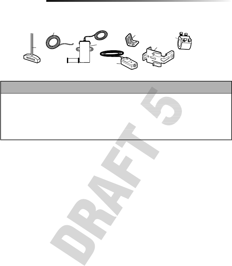
34
Repair Parts
Installation Parts
6
1
2
3
5
4
7
KEY
NO.
PART NO. DESCRIPTION KEY
NO.
PART NO. DESCRIPTION
1 041A4582 Emergency release rope and handle
assembly
2 041B4494-1 2-Conductor bell wire - white and
white/red
3 041A6104 Cable tension monitor
4 041A5034 Safety Reversing Sensor kit (receiving
and sending sensors) with 2-conductor
bell wire attached
5 041C0902 Mounting bracket
6 41A5266-1 Safety reversing sensor brackets (2)
7 041D8615 Collar with set screws
NOT SHOWN
114A5061 User's Guide
114A5075 Quick Start Guide
114A5061 User's Guide
114A5075 Quick Start Guide
5 041C0902 Mounting bracket
6 41A5266-1 Safety reversing sensor brackets (2)
7 041D8615 Collar with set screws
NOT SHOWN
114A5061 User's Guide
5 041C0902 Mounting bracket
6 41A5266-1 Safety reversing sensor brackets (2)
7 041D8615 Collar with set screws
NOT SHOWN
114A5061 User's Guide
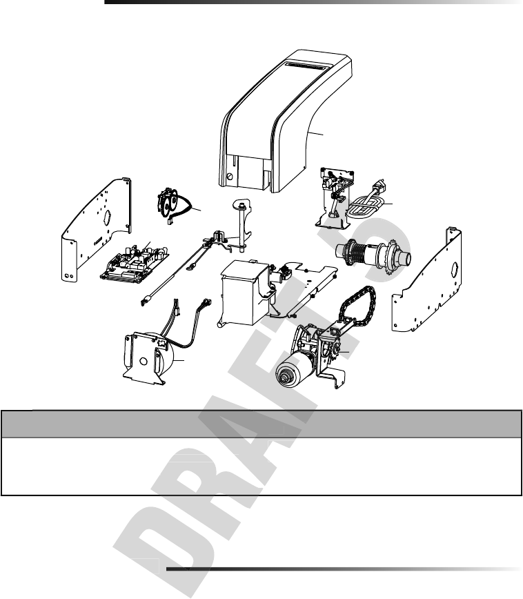
35
Repair Parts
Garage Door Opener Assembly Parts
Address repair parts order to:
LiftMaster
6050 S. Country Club Rd.
Tucson, AZ 85706
For installation and service information call:
1-800-528-9131
Or visit us online at:
LiftMaster.com
Before calling, please have the model number of the garage door opener. If you are calling about a troubleshooting
issue, it is recommended that you have access to your garage door opener while calling. If you are ordering a repair
part please have the following information: part number, part name, and model number.
Contact Information
STOP!
This garage door opener WILL NOT work until the
safety reversing sensors are properly installed and aligned.
3
25
4
1
6
KEY
NO.
PART NO. DESCRIPTION KEY
NO.
PART NO. DESCRIPTION
1 050DCRJWF Logic Board
2 041B8861 Travel Module with Wire Harness
3 041C0296 Transformer
4 041D1624-2 Motor
5 041D0190 Power cord
6 041D9042 Cover
NOT SHOWN
041D9044 Battery Door and Logic Board Door
ation
2 041B8861 Travel Module with Wire Harness
3 041C0296 Transformer
KEY
NO.
2 041B8861 Travel Module with Wire Harness
5 041D0190 Power cord
6 041D9042 Cover
NOT SHOWN
PART NO.
4
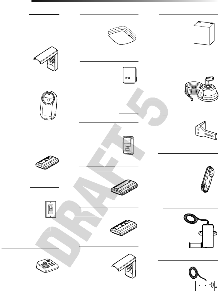
36
Extension Brackets:
(Optional) For safety
reversing sensor installation
onto the wall or fl oor.
Security+ 2.0® Wireless Door Control:
Push bar, light feature and
auxiliary button. Includes
battery.
Alternate Mounting Kit:
This kit allows model 8500W
to be mounted below the
torsion bar in the case where
the torsion bar is not round
or the normal mounting area
is obstructed.
Cable Tension
Monitor:
Cable tension
monitor with 33 foot
cord.
Garage Door and Gate Monitor:
Monitor open/closed
status for up to 4 MyQ®
compatible garage door
openers or gate operators
and close them from anywhere in the
home.
Remote Light Control:
Automatically control your
lights using your garage door
opener, a Security+ 2.0® remote
control or a LiftMaster® Internet
Gateway. Plugs into any interior outlet.
Remote Light Switch:
Automatically control your
lights using your garage door
opener, a Security+ 2.0® remote
control or a LiftMaster® Internet
Gateway. Simply replaces your current
wired wall switch.
3-Button MAX Remote Control:
Includes visor clip.
41A5281
877MAX
374UT
893MAX
Mini Universal Remote
Control:
The Mini Universal Remote
Control can be programmed
to activate up to two
products, such as a garage
door opener, MyQ® light
controls, gate operator, or
commercial door operator.
829LM
Battery Backup:
Provides backup power
to the door opener.
The battery has enough
power for 30 hours of
standby power or up to
20 cycles over a 24 hour period.
485LM
885LM
825LM
823LM
480LM
041A6104
975LM
Laser Park Assist:
Laser enables
homeowners to
precisely park vehicles
in the garage.
MyQ LED Remote
Light:
Wireless light that can
program to the door
opener or a remote
control.
827LM
MAX ACCESSORIES
Compatible with LiftMaster® garage door
openers manufactured since 1993.
MYQ® ACCESSORIES
STANDARD ACCESSORIES
Single Button Security+ 2.0 Remote
Control:
Includes visor clip.
891LM
3-Button Security+ 2.0 Remote Control:
Includes visor clip.
893LM
Wireless Keyless Entry:
For use outside of the
home to enable access
to the garage using a
4-digit PIN.
Wireless Keyless Entry:
For use outside of the
home to enable access to
the garage using a 4-digit
PIN.
877LM
Accessories
Automatic Door Lock:
The automatic door
lock is used to prevent
the door from being
manually opened once
the door is fully closed.
841LM
Gateway. Simply replaces your current
Wireless Keyless Entry:
For use outside of the
home to enable access
877LM
3-Button Security+ 2.0 Remote Control:
Includes visor clip.
893LM
Control:
Includes visor clip.
3-Button Security+ 2.0 Remote Control:
Single Button Security+ 2.0 Remote
Wireless Door Control:
Push bar, light feature and
auxiliary button. Includes
480LM
Extension Brackets:
41A5281
in the garage.
Extension Brackets:
(Optional) For safety
41A5281
in the garage.

37
Warranty
LIFTMASTER® LIMITED WARRANTY
LiftMaster® (“Seller”) warrants to the fi rst retail purchaser of this product, for the residence in which this product
is originally installed, that it is free from defects in materials and/or workmanship for a specifi c period of time as
defi ned below (the “Warranty Period”). The warranty period commences from the date of purchase.
WARRANTY PERIOD
Parts Motor Accessories Battery Backup
5 years Lifetime 1 year 1 year
The proper operation of this product is dependent on your compliance with the instructions regarding installation,
operation, and maintenance and testing. Failure to comply strictly with those instructions will void this limited
warranty in its entirety.
If, during the limited warranty period, this product appears to contain a defect covered by this limited warranty,
call 1-800-528-9131, toll free, before dismantling this product. You will be advised of disassembly and shipping
instructions when you call. Then send the product or component, pre-paid and insured, as directed to our service
center for warranty repair. Please include a brief description of the problem and a dated proof-of-purchase receipt
with any product returned for warranty repair. Products returned to Seller for warranty repair, which upon receipt
by Seller are confi rmed to be defective and covered by this limited warranty, will be repaired or replaced (at Seller’s
sole option) at no cost to you and returned pre-paid. Defective parts will be repaired or replaced with new or factory
rebuilt parts at Seller’s sole option. [You are responsible for any costs incurred in removing and/or reinstalling the
product or any component.]
ALL IMPLIED WARRANTIES FOR THE PRODUCT, INCLUDING BUT NOT LIMITED TO ANY IMPLIED WARRANTIES
OF MERCHANTABILITY AND FITNESS FOR A PARTICULAR PURPOSE, ARE LIMITED IN DURATION TO THE
APPLICABLE LIMITED WARRANTY PERIOD SET FORTH ABOVE FOR THE RELATED COMPONENT(S), AND NO
IMPLIED WARRANTIES WILL EXIST OR APPLY AFTER SUCH PERIOD. Some States and Provinces do not allow
limitations on how long an implied warranty lasts, so the above limitation may not apply to you. THIS LIMITED
WARRANTY DOES NOT COVER NON-DEFECT DAMAGE, DAMAGE CAUSED BY IMPROPER INSTALLATION,
OPERATION OR CARE (INCLUDING, BUT NOT LIMITED TO ABUSE, MISUSE, FAILURE TO PROVIDE REASONABLE
AND NECESSARY MAINTENANCE, UNAUTHORIZED REPAIRS OR ANY ALTERATIONS TO THIS PRODUCT), LABOR
CHARGES FOR REINSTALLING A REPAIRED OR REPLACED UNIT, REPLACEMENT OF CONSUMABLE ITEMS
(E.G., BATTERIES IN REMOTE CONTROL TRANSMITTERS AND LIGHT BULBS), OR UNITS INSTALLED FOR NON-
RESIDENTIAL USE. THIS LIMITED WARRANTY DOES NOT COVER ANY PROBLEMS WITH, OR RELATING TO, THE
GARAGE DOOR OR GARAGE DOOR HARDWARE, INCLUDING BUT NOT LIMITED TO THE DOOR SPRINGS, DOOR
ROLLERS, DOOR ALIGNMENT OR HINGES. THIS LIMITED WARRANTY ALSO DOES NOT COVER ANY PROBLEMS
CAUSED BY INTERFERENCE. UNDER NO CIRCUMSTANCES SHALL SELLER BE LIABLE FOR CONSEQUENTIAL,
INCIDENTAL OR SPECIAL DAMAGES ARISING IN CONNECTION WITH USE, OR INABILITY TO USE, THIS PRODUCT.
IN NO EVENT SHALL SELLER’S LIABILITY FOR BREACH OF WARRANTY, BREACH OF CONTRACT, NEGLIGENCE
OR STRICT LIABILITY EXCEED THE COST OF THE PRODUCT COVERED HEREBY. NO PERSON IS AUTHORIZED TO
ASSUME FOR US ANY OTHER LIABILITY IN CONNECTION WITH THE SALE OF THIS PRODUCT.
Some states and provinces do not allow the exclusion or limitation of consequential, incidental or special damages,
so the above limitation or exclusion may not apply to you. This limited warranty gives you specifi c legal rights, and
you may also have other rights, which vary from state to state and province to province.
OR STRICT LIABILITY EXCEED THE COST OF THE PRODUCT COVERED HEREBY. NO PERSON IS AUTHORIZED TO
ASSUME FOR US ANY OTHER LIABILITY IN CONNECTION WITH THE SALE OF THIS PRODUCT.
Some states and provinces do not allow the exclusion or limitation of consequential, incidental or special damages,
so the above limitation or exclusion may not apply to you. This limited warranty gives you specifi
you may also have other rights, which vary from state to state and province to province.
ROLLERS, DOOR ALIGNMENT OR HINGES. THIS LIMITED WARRANTY ALSO DOES NOT COVER ANY PROBLEMS
CAUSED BY INTERFERENCE. UNDER NO CIRCUMSTANCES SHALL SELLER BE LIABLE FOR CONSEQUENTIAL,
INCIDENTAL OR SPECIAL DAMAGES ARISING IN CONNECTION WITH USE, OR INABILITY TO USE, THIS PRODUCT.
IN NO EVENT SHALL SELLER’S LIABILITY FOR BREACH OF WARRANTY, BREACH OF CONTRACT, NEGLIGENCE
OR STRICT LIABILITY EXCEED THE COST OF THE PRODUCT COVERED HEREBY. NO PERSON IS AUTHORIZED TO
ASSUME FOR US ANY OTHER LIABILITY IN CONNECTION WITH THE SALE OF THIS PRODUCT.
Some states and provinces do not allow the exclusion or limitation of consequential, incidental or special damages,
so the above limitation or exclusion may not apply to you. This limited warranty gives you specifi
AND NECESSARY MAINTENANCE, UNAUTHORIZED REPAIRS OR ANY ALTERATIONS TO THIS PRODUCT), LABOR
CHARGES FOR REINSTALLING A REPAIRED OR REPLACED UNIT, REPLACEMENT OF CONSUMABLE ITEMS
(E.G., BATTERIES IN REMOTE CONTROL TRANSMITTERS AND LIGHT BULBS), OR UNITS INSTALLED FOR NON-
RESIDENTIAL USE. THIS LIMITED WARRANTY DOES NOT COVER ANY PROBLEMS WITH, OR RELATING TO, THE
GARAGE DOOR OR GARAGE DOOR HARDWARE, INCLUDING BUT NOT LIMITED TO THE DOOR SPRINGS, DOOR
ROLLERS, DOOR ALIGNMENT OR HINGES. THIS LIMITED WARRANTY ALSO DOES NOT COVER ANY PROBLEMS
CAUSED BY INTERFERENCE. UNDER NO CIRCUMSTANCES SHALL SELLER BE LIABLE FOR CONSEQUENTIAL,
INCIDENTAL OR SPECIAL DAMAGES ARISING IN CONNECTION WITH USE, OR INABILITY TO USE, THIS PRODUCT.
IN NO EVENT SHALL SELLER’S LIABILITY FOR BREACH OF WARRANTY, BREACH OF CONTRACT, NEGLIGENCE
APPLICABLE LIMITED WARRANTY PERIOD SET FORTH ABOVE FOR THE RELATED COMPONENT(S), AND NO
IMPLIED WARRANTIES WILL EXIST OR APPLY AFTER SUCH PERIOD. Some States and Provinces do not allow
limitations on how long an implied warranty lasts, so the above limitation may not apply to you. THIS LIMITED
WARRANTY DOES NOT COVER NON-DEFECT DAMAGE, DAMAGE CAUSED BY IMPROPER INSTALLATION,
OPERATION OR CARE (INCLUDING, BUT NOT LIMITED TO ABUSE, MISUSE, FAILURE TO PROVIDE REASONABLE
AND NECESSARY MAINTENANCE, UNAUTHORIZED REPAIRS OR ANY ALTERATIONS TO THIS PRODUCT), LABOR
CHARGES FOR REINSTALLING A REPAIRED OR REPLACED UNIT, REPLACEMENT OF CONSUMABLE ITEMS
(E.G., BATTERIES IN REMOTE CONTROL TRANSMITTERS AND LIGHT BULBS), OR UNITS INSTALLED FOR NON-
RESIDENTIAL USE. THIS LIMITED WARRANTY DOES NOT COVER ANY PROBLEMS WITH, OR RELATING TO, THE
rebuilt parts at Seller’s sole option. [You are responsible for any costs incurred in removing and/or reinstalling the
ALL IMPLIED WARRANTIES FOR THE PRODUCT, INCLUDING BUT NOT LIMITED TO ANY IMPLIED WARRANTIES
OF MERCHANTABILITY AND FITNESS FOR A PARTICULAR PURPOSE, ARE LIMITED IN DURATION TO THE
APPLICABLE LIMITED WARRANTY PERIOD SET FORTH ABOVE FOR THE RELATED COMPONENT(S), AND NO
IMPLIED WARRANTIES WILL EXIST OR APPLY AFTER SUCH PERIOD. Some States and Provinces do not allow
limitations on how long an implied warranty lasts, so the above limitation may not apply to you. THIS LIMITED
call 1-800-528-9131, toll free, before dismantling this product. You will be advised of disassembly and shipping
instructions when you call. Then send the product or component, pre-paid and insured, as directed to our service
center for warranty repair. Please include a brief description of the problem and a dated proof-of-purchase receipt
with any product returned for warranty repair. Products returned to Seller for warranty repair, which upon receipt
rmed to be defective and covered by this limited warranty, will be repaired or replaced (at Seller’s
sole option) at no cost to you and returned pre-paid. Defective parts will be repaired or replaced with new or factory
rebuilt parts at Seller’s sole option. [You are responsible for any costs incurred in removing and/or reinstalling the
If, during the limited warranty period, this product appears to contain a defect covered by this limited warranty,
call 1-800-528-9131, toll free, before dismantling this product. You will be advised of disassembly and shipping
instructions when you call. Then send the product or component, pre-paid and insured, as directed to our service
center for warranty repair. Please include a brief description of the problem and a dated proof-of-purchase receipt
with any product returned for warranty repair. Products returned to Seller for warranty repair, which upon receipt
rmed to be defective and covered by this limited warranty, will be repaired or replaced (at Seller’s
sole option) at no cost to you and returned pre-paid. Defective parts will be repaired or replaced with new or factory
rebuilt parts at Seller’s sole option. [You are responsible for any costs incurred in removing and/or reinstalling the

38
Wi-Fi® is a registered trademark of Wi-Fi Alliance.
App Store is a service mark of Apple Inc.
Google Play is a trademark of Google Inc.
© 2017, LiftMaster
114A4961 All Rights Reserved