Chamberlain Group The 6597 Part 15 Spread Spectrum Transmitter Transceiver User Manual
Chamberlain Group Inc, The Part 15 Spread Spectrum Transmitter Transceiver
USER MANUALS

9
FEATURES
INTRODUCTION
FEATURES
OPERATOR FEATURES
CONTROL BOARD FEATURES
EXPANSION BOARD FEATURES
• Advanced "Centerpiece" Control Board
• EMI AC Power Surge Protection and Filter Board
- Main AC voltage input selection: 120 Vac (factory setting) or
240 Vac (field change)
• DC motor
• AC powered with integrated battery backup
• 24 Vdc accessory power
• Programmable with up to 50 remote controls, compatible with: Security MAX
codes at either 310, 315, or 390 MHz
• Manual - Secure power failure selection
• SAMS compatible
• Slow-start and slow-stop gate motion
• Reset Button
• Audible Alarm
• Internal Heater option (factory installed or field installed) 120 Vac powered ONLY
• Non-Scissor Action swing arm with easy arm disconnect
• Integrated internal antenna with external antenna option
• Electronic Limit adjustment and control
• Adjustable reversal force
• Adjustable Timer-to-Close (TTC)
• Maximum Run Timer
• Bipart Delay switch (dual gate applications)
• Feedback and Diagnostic LEDs
• Integrated Radio Receiver, Single Button Control (SBC) and 3-Button Station
control, three radio frequencies supporting Security MAX
• COMMANDS:
- OPEN, CLOSE, or STOP: accessory connection and on-board button
- Single Button Close (SBC): accessory connection
- FIRE DEPARTMENT OPEN: accessory connection
- INTEGRATED RADIO RECEIVER:
• LOOPS:
- EXIT, SHADOW, or INTERRUPT LOOP: plug-in loop detector (Model SPI) and
accessory connection
• Plug-in Loop Detector Connectors (Model LOOPDETLM Loop Detector)
- SHADOW
- INTERRUPT
- EXIT, with Fail Safe/Fail Secure selection
• Quick-Close ON/OFF selection switch
• AC Fail Open/Battery selection switch
• Low Battery Open/Close selection switch
• Anti-Tail ON/OFF selection switch
• Single Button Control (SBC) accessory connection
• 3-Button station accessory connection
• AUX Relays (2) each independently selectable operation:
- OPEN LIMIT: ON at open limit switch
- CLOSE LIMIT: ON at close limit switch
- GATE MOVING: ON with gate moving
- PRE-ALERT DELAY: ON 3 seconds before gate motion
- TAMPER: ON when gate manually pulled from close limit
- POWER: ON with AC or Solar power available
- CYCLE QUANTITY: LEDs blink operational cycle count
10
PREPARATION
Conduit must be UL approved for low and high voltage. Consider the operator
placement BEFORE installing the pad or post.
Gate must be constructed and installed according to ASTM F2200 standards (refer
to page 4). Gate must fit specifications of operator (refer to specifications).
Concrete Pads
GATE CONDUIT & CONCRETE PAD
SITE PREPARATION
Check the national and local building codes BEFORE installation.
11
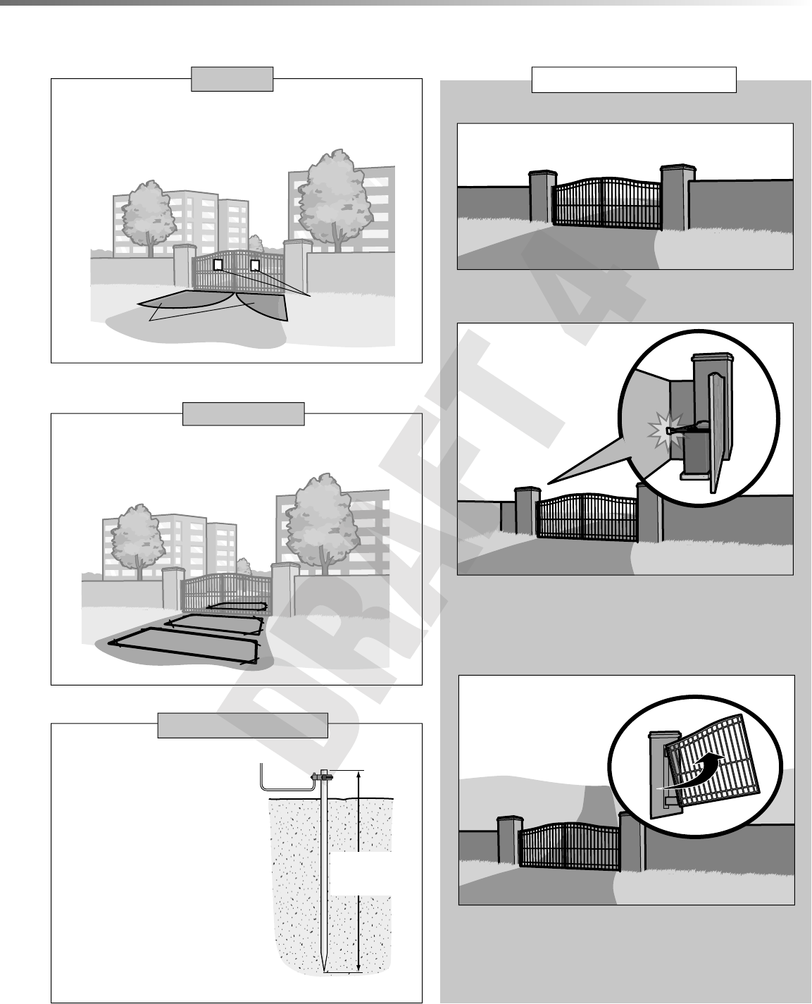
SITE PREPARATION
VEHICLE LOOPS
The vehicle loops allow the gate to stay open when vehicles are obstructing the
gate path. Suggested for vehicles 14 feet (4.27 m) or longer. Vehicle loops are
not required but are recommended.
!
!
Entrapment protection devices are required to protect against any entrapment
or safety conditions encountered in your gate application (refer to page 5 for
more details). Install warning signs on both sides of the gate.
Proper grounding gives an electrical
charge, such as from an electrical
static discharge or a near lightning
strike, a path from which to dissipate
its energy safely into the earth.
Without this path, the intense energy
generated by lightning could be
directed towards the gate operator.
Although nothing can absorb the
tremendous power of a direct lightning
strike, proper grounding can protect
the gate operator in most cases.
(Inside Property)
Entrapment Danger
Warning Signs
Check national and local
codes for proper depth
SAFETY
EARTH GROUND ROD
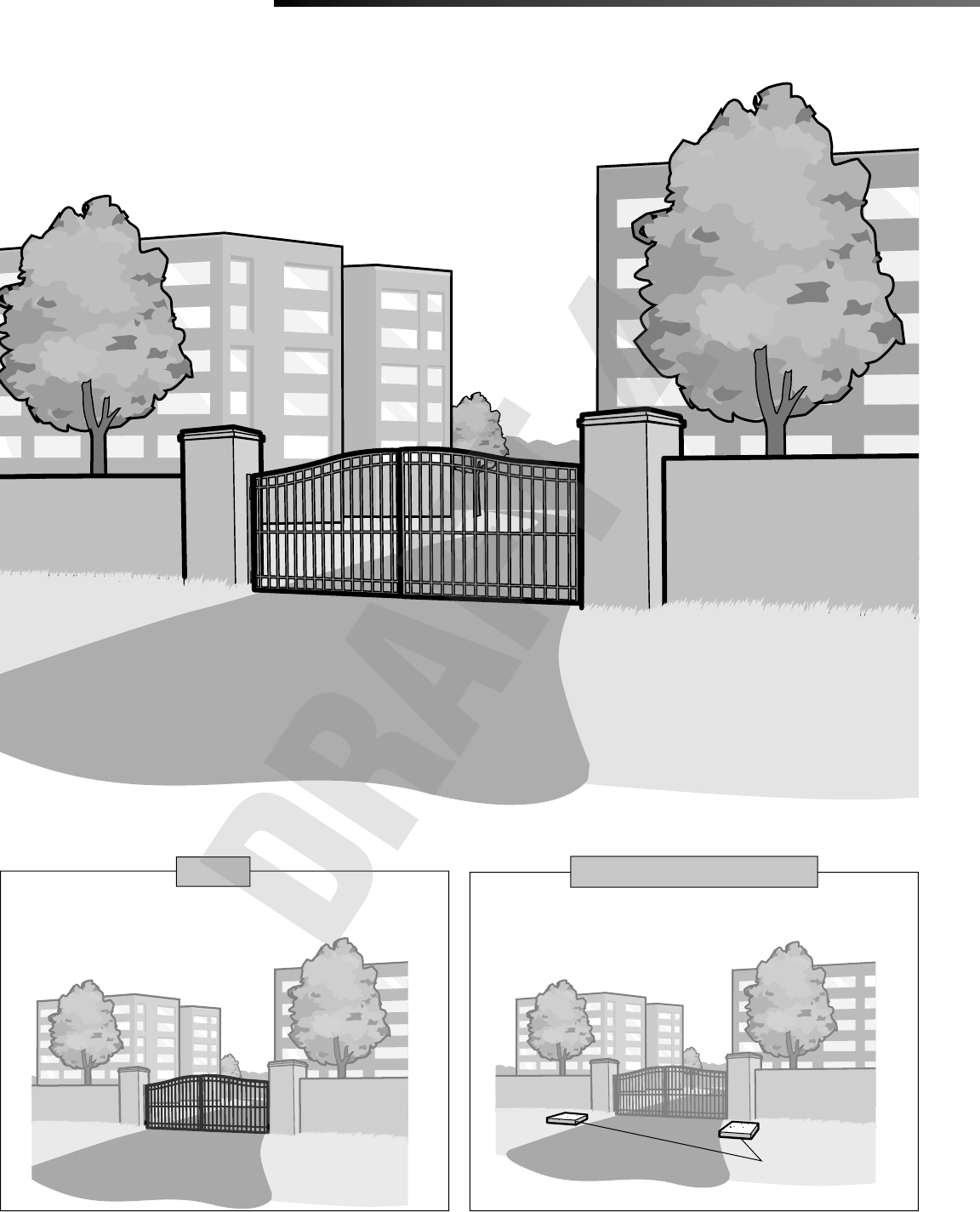
TYPES OF INSTALLATIONS
STANDARD INSTALLATION
COMPACT INSTALLATION
UPHILL DRIVEWAY INSTALLATION
The illustration is an example of a standard installation.
The illustration is an example of a compact installation. If the operator arm
will hit an obstruction when the gate is in the open position follow the
directions for Compact Installation.
The illustration is an example of an uphill driveway installation. If installing
the operator on a hill, a special swivel arm and hinges are required (not
provided).
(Inside Property)
(Inside Property)
(Outside Property)
(Side View)

12
MOUNTING FOOTPRINT
13.6"
11"
14"
.63"
CONDUIT LOCATION 12.2"
6.1"
2.49"
14.6"
17"
12" Output
Shaft
STANDARD INSTALLATION ONLY
INSTALLATION
STANDARD INSTALLATION ONLY
For compact installation start on page 14.
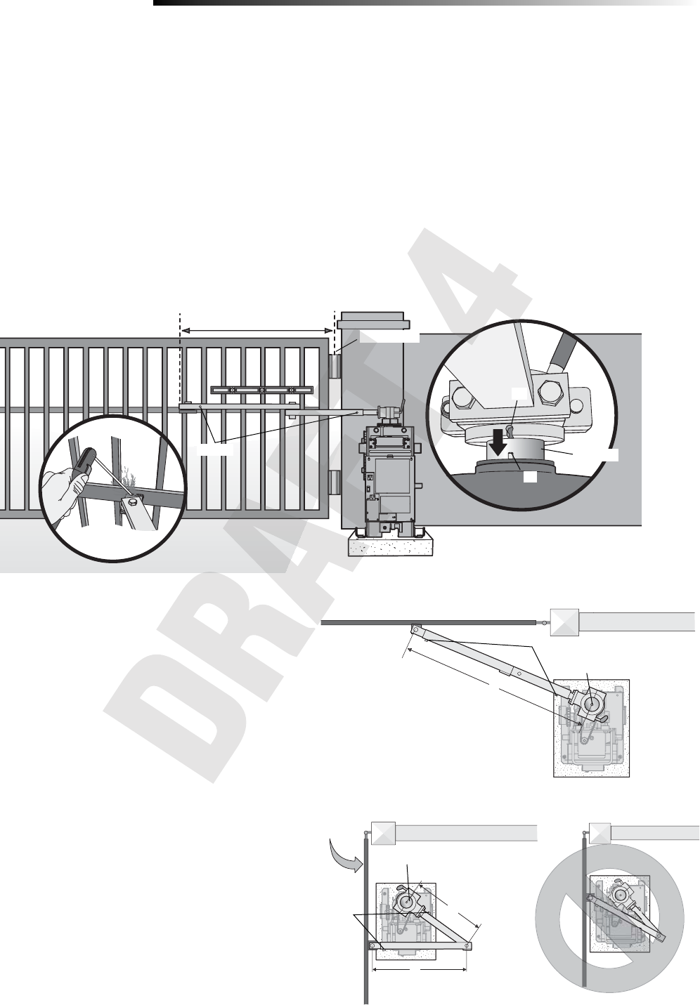
DETERMINE LOCATION FOR CONCRETE PAD
AND OPERATOR
DO NOT run the operator until instructed.
Below is a recommended guide for positioning the concrete pad:
Measure 1/4 the length of the gate from the gate hinge center. This is A.
Subtract 12-16 inches from A to get B, the distance from the center of the
output shaft to the center of the gate hinge.
Open the gate 90
°.
The distance from the gate to the center of the output
shaft must be a minimum of 9 inches.
1/4 1/4 1/4 A
B
minimum
of 9"
Output Shaft
12
328"
24"
90°
Gate Hinge
TOP VIEW OF OPERATOR AND GATE
CONCRETE PAD AND OPERATOR ATTACHMENT
Check the national and local building codes before installation. NOTE: When lifting
the operator use the handle to avoid damaging the operator.
Install the electrical conduit.
Pour a concrete pad (reinforced concrete is recommended). The concrete pad
should be 6 inches above the ground and deeper than the frost line. Ensure the
pad is tall enough to avoid possible flooding.
Secure the operator to the concrete pad with appropriate fasteners.
NOTE: An alternative to a concrete pad is to post mount the operator (refer to
accessories).
4 Concrete Anchors
1/2" x 3 1/2"
Below the frost line.
Check all national and
local codes.
6" Above Ground
28"
24"
1
3
2
1
2
3
1
2
3
13
STANDARD INSTALLATION ONLY
INSTALLATION
STANDARD INSTALLATION ONLY
POSITION THE GATE BRACKET
NOTE: It may be necessary to attach horizontal reinforcement to the gate before
attaching the gate bracket.
Position the operator arm onto the output shaft so that the pin slides into
the slot.
Measure 1/4 the length of the gate from the hinge center.
Make sure the operator arm is level and tack weld the gate bracket in this
position. Use the set screws on the arm to temporarily hold the arm in place
while determining the correct measurements.
1
2
3
Tack weld
Gate Hinge Center
1/4 of gate length
1
2
3Output Shaft
Slot
Pin
ADJUST THE OPERATOR ARM LENGTH
NOTE: The length of the arm can be adjusted if necessary. If adjusting the length,
ensure that both sections of the arm are adjusted proportionally. Use the set screws
on the arm to temporarily hold the arm in place while determining the correct
measurements.
Close the gate and measure the distance of the operator arm from the gate
bracket to the output shaft center. This distance is E.
Open the gate 90° (do not allow arms to scissor when open). Measure both
sections of the arm (D and C). The arm lengths are correct as long as
C+D=E (arm should be perpendicular to the gate in the open position as
shown).
Proceed to PAGE 16.
1
2
Output Shaft
Gate Open
90°
1
2
E
D
C
TOP VIEW - CLOSED GATE
TOP VIEW - OPEN GATE
Output Shaft
Set Screws
Set Screws
Set Screws
14
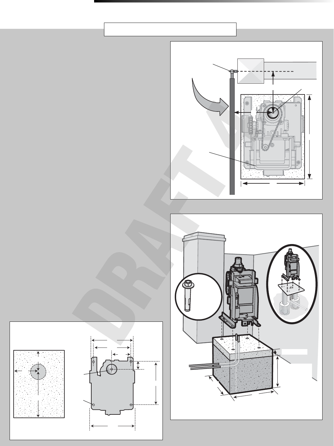
DETERMINE LOCATION FOR CONCRETE PAD
AND OPERATOR
DO NOT run the operator until instructed.
Refer to the illustration to determine the measurements and location of the
concrete pad.
NOTE: When lifting the operator use the handle to avoid damaging the
operator.
26-1/2"
9"
Output Shaft Center
28"
24"
Gate Hinge Center
TOP VIEW OF OPERATOR AND GATE
Gate Open 90°
CONCRETE PAD AND OPERATOR ATTACHMENT
Check the national and local building codes before installation.
Install the electrical conduit.
Pour a concrete pad (reinforced concrete is recommended). The concrete
pad should be 6 inches above the ground and deeper than the frost line.
Ensure the pad is tall enough to avoid possible flooding.
Secure the operator to the concrete pad with appropriate fasteners.
NOTE: An alternative to a concrete pad is to post mount the operator (refer to
accessories).
2
4 Concrete Anchors
1/2" x 3 1/2"
6" Above Ground
28"
24"
1
3
2Below the frost line.
Check all national and
local codes.
COMPACT INSTALLATION ONLY
INSTALLATION
COMPACT INSTALLATION ONLY
Post Mount
Handle
MOUNTING FOOTPRINT
13.6"
14"
.63"
CONDUIT LOCATION
12.2"
6.1"
2.49"
14.6"
(cover mounting distance)
Output
Shaft
NEED INFO
1
3
11"
17"
12"
15
COMPACT INSTALLATION ONLY
INSTALLATION
COMPACT INSTALLATION ONLY
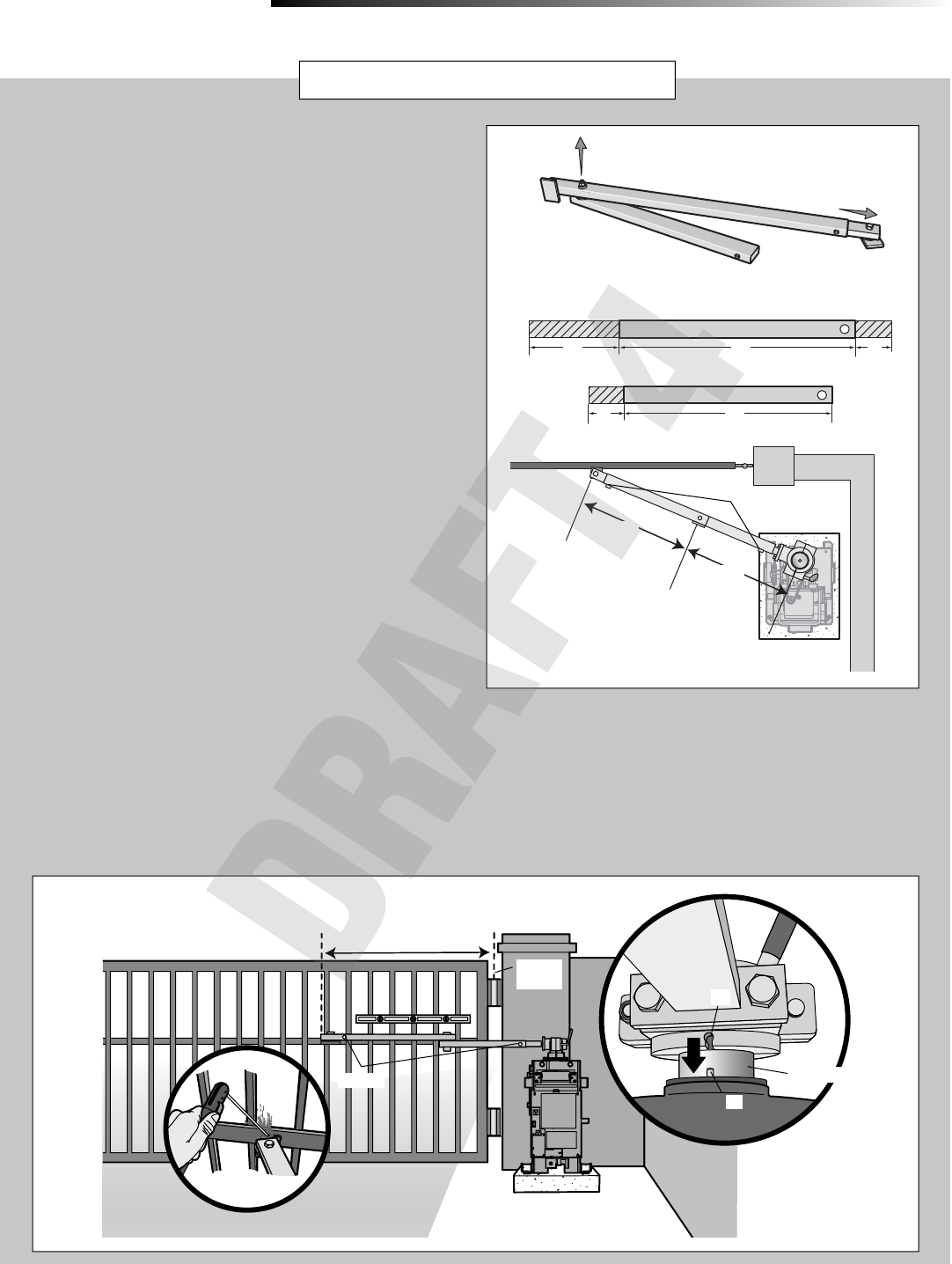
SHORTEN THE OPERATOR ARM
For a compact installation the operator arm will have to be shortened.
Take the operator arm apart and remove the inner sleeves from the
outer tubing.
Cut the outer tubing of the operator arm sections to the lengths shown.
Put the arm back together and adjust the arm to the measurements
as shown. Use the set screws on the arm to temporarily hold the arm in
place while determining the correct measurements.
1
2
3
CUT long arm section
short arm section
CUT
CUT
10" 22" 4"
20"4"
23"
25-1/2"
POSITION THE GATE BRACKET
NOTE: It may be necessary to attach horizontal reinforcement to the gate
before attaching the gate bracket. Use the set screws on the arm to temporarily
hold the arm in place while determining the correct measurements.
Position the operator arm onto the output shaft so that the pin slides into
the slot.
Measure 33 inches from the gate hinge center.
Make sure the operator arm is level and tack weld the gate bracket in
this position.
2
Tack weld
Gate Hinge
Center
33"
2
3
1
2
3
1
3
1
Output Shaft
Slot
Pin
Set Screws
Set Screws