Chamberlain Group The 7644 Wireless Wall Switch with Frequency Hopping Spread Spectrum Transmitter User Manual 114A4349lr2 indd
Chamberlain Group Inc, The Wireless Wall Switch with Frequency Hopping Spread Spectrum Transmitter 114A4349lr2 indd
Exhibit D Users Manual per 2 1033 b3
To prevent possible SERIOUS INJURY or DEATH from
electrocution or fire:
• Turn off power at the fuse box or circuit breaker BEFORE
proceeding.
• The light control is ONLY for indoor use.
• Installation and wiring MUST be in compliance with ALL
local electrical and building codes.
MODEL 823LM
REMOTE LIGHT SWITCH
The Remote Light Switch offers a convenient
way to control the lights in your home. The
Remote Light Switch is compatible with
Security✚ 2.0™ and MyQ™ products. The
Remote Light Switch is compatible with up to
8 Security✚ 2.0™ remote controls and a
combination of up to 8 MyQ™ enabled garage
door openers or LiftMaster® Internet Gateway
devices. This product is NOT recommended for
control of household appliances or fans. Not for
use with 3-way or 4-way switch combinations.
SPECIFICATIONS
Bulb Type: Compact fluorescent, incandescent,
or LED.
Max Load Rating:. . . . . . . . . . . . . . . 300 Watts
Incandescent Lamp . . . . . . . . . . . . . 300 Watts
Compact Fluorescent Lamp (CFL). . .2.5 Amps
Voltage . . . . . . . . . . . . . . . . . . . . . . . . . 120 Vac NOTE: The wall plate is
not provided.
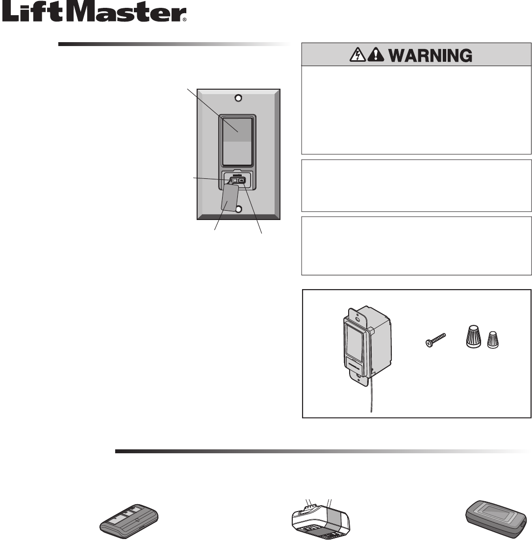
OVERVIEW
MODES OF OPERATION
REMOTE CONTROL OPERATION:
Allows you to activate the
remote light switch from a
remote control.
The remote light switch can be programmed to Security✚ 2.0™ remote controls, MyQ™ garage door openers, or LiftMaster® Internet Gateway devices.
GARAGE DOOR OPENER OPERATION:
Allows you to synchronize
the remote light switch with
your garage door opener
light bulbs. Example: The
garage door opener light
bulbs are set to automatically turn off after 4 ½
minutes, the remote light switch will also turn
off after 4 ½ minutes.
INTERNET GATEWAY OPERATION:
Allows you to activate the
remote light switch from a
web browser (requires the
internet gateway accessory
model 828LM).
Switch
LED
NOTICE: To comply with FCC and/or Industry Canada (IC) rules, adjustment or modifi cations of
this transceiver are prohibited. THERE ARE NO USER SERVICEABLE PARTS.
This device complies with Part 15 of the FCC rules and IC RSS-210. Operation is subject to
the following two conditions: (1) this device may not cause harmful interference, and (2) this
device must accept any interference received, including interference that may cause undesired
operation.
AVIS : Les règles de la FCC et/ou d’Industrie Canada (IC) interdisent tout ajustement ou toute
modifi cation de ce récepteur. IL N’EXISTE AUCUNE PIÈCE SUSCEPTIBLE D’ÊTRE ENTRETENUE
PAR L’UTILISATEUR.
Cet appareil est conforme aux dispositions de la partie 15 du règlement de la FCC et de la norme
IC RSS-210. Son utilisation est assujettie aux deux conditions suivantes : (1) ce dispositif ne
peut causer des interférences nuisibles, et (2) ce dispositif doit accepter toute interférence reçue,
y compris une interférence pouvant causer un fonctionnement non souhaité.
Learn ButtonCover
CARTON INVENTORY
Screws (2)
Remote Light Switch
Wire Nuts
1
(2)
(1)
BEFORE YOU BEGIN:
This device REQUIRES a ground; if a ground is not available, contact a
qualified electrician. If you are not experienced and familiar with electrical
wiring and electrical codes, contact a qualified electrician. Some codes
require installation by a qualified electrician.
NOTE: Install in accordance with all national and local codes.
1. Disconnect power at the circuit breaker or fuse box BEFORE
proceeding.
2. Remove wall plate and set aside for re-assembly.
REMOVE OLD WALL SWITCH:
1. Remove switch from switch box.
2. During to removal, identify or label the load and line wires.
NOTE: Typically a line wire is the incoming hot wire from the circuit
breaker. The load wire is the wire supplying power between the switch
and the light.
3. Keep load wires separated from line wire.
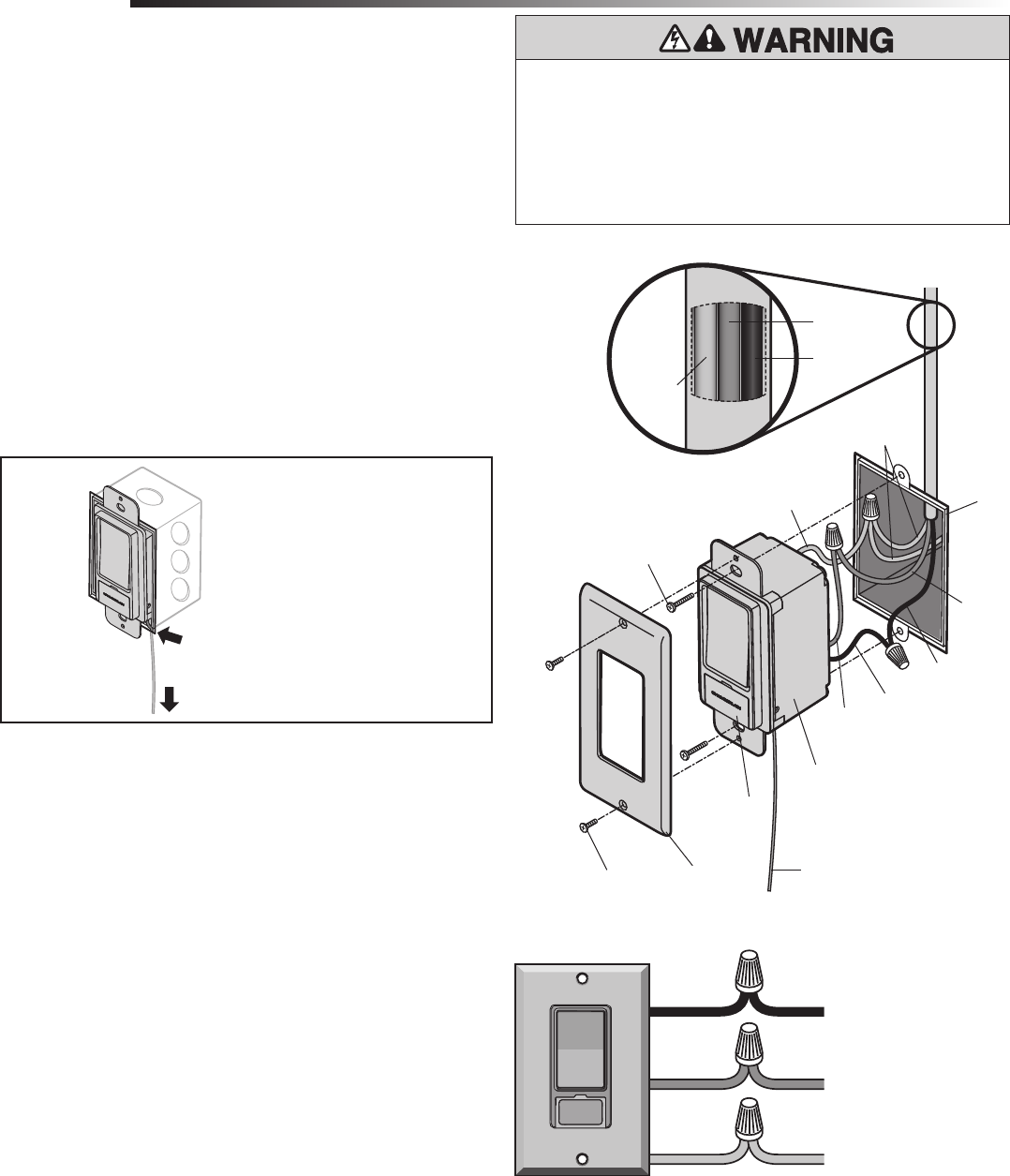
INSTALL NEW SWITCH:
1. Identify the antenna routing (Figure 2).
2. Connect the wires (Figure 3).
• Green wire to ground.
Connect the green wire on the new switch to the exposed copper
ground, green wire, or to the ground connection within metal
switch box. (NOTE: If ground doesn’t exist contact an electrician
to add a ground. This product will not function without a proper
ground.)
• Red wire to load.
• Black wire to line.
3. Secure connections with a wire nut and wrap each wire nut with
electrical tape.
NOTE: Turn all wire nuts clockwise, making sure the bare wires are
covered. Tug on each wire nut to make sure the connections are good.
4. Carefully pack the wiring back into switch box. Make sure the wires are
not pinched or strained. Make sure the antenna is hanging straight
down between the switch box and the drywall.
5. Fasten the remote light switch to switch box with the screws
(provided).
6. Fasten the wall plate securely over the switch box with the original
screws from the wall plate.
7. Turn on the power to circuit at fuse box or circuit breaker.
8. Test the light switch, manually press the light switch to ensure the
light is functional. If it is not functional, see Troubleshooting.
9. Open the cover on the light switch so you can view the LED.
10. Allow up to 10 minutes for remote light switch to power up properly,
when the LED stops flashing (up to 10 minutes) proceed to
Programming.
INSTALLATION
Junction
Box
Black
Wire
Black Wire
Line
Red Wire
Load
Green Wire
Ground
Cover
Red
Wire
Line
Wire
Line
Load
Wire
Load
Remote Light
Switch
Green Wires
(Ground)
Ground
Screws
Figure 1
Figure 3
Figure 2
For optimal range fully extend the
antenna. Feed antenna wire between a
gap between the switch box and drywall.
Wall Plate
(existing-not
provided)
Screws
(not provided)
Green
Wire
Inside of
cable
Yellow Antenna
To prevent possible SERIOUS INJURY or DEATH from electrocution or
fire:
• Turn off power at the fuse box or circuit breaker BEFORE
proceeding.
• The light control is ONLY for indoor use.
• Installation and wiring MUST be in compliance with ALL local
electrical and building codes.
2
IMPORTANT NOTE: This illustration is only an example and your application and wiring may
look different.
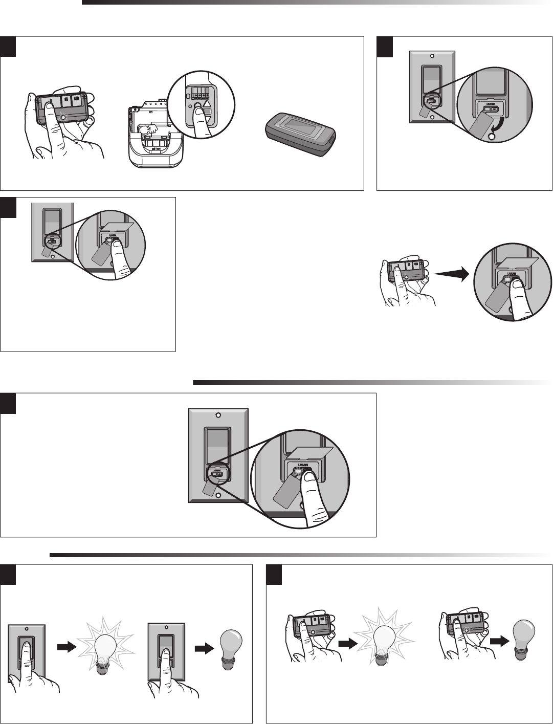
1Press and HOLD the “LEARN”
button until the LED goes out
(approximately 6 seconds). All
codes are now erased.
TO ERASE ALL CODES FROM MEMORY
TESTING
Press the switch to the
ON position. The light
should turn on.
Test the remote control operation at various locations within your home
for convenience and range. The remote control range will vary depending
on your house and wiring construction. The range may be reduced by
metal lath, foil-backed insulation or aluminum siding.
Press remote control
button. The light should
turn on.
Press the switch to the
OFF position. The light
should turn off.
Press again and the light
should turn off.
1 2
PROGRAMMING
1
3
Then press and release the “LEARN” button.
The LED will FLASH once. Programming is
complete.
NOTE: If needed, press and hold the
“LEARN” button with a narrow instrument.
IMPORTANT NOTE: Allow 10 minutes for remote light switch to power up properly, prior to proceeding to Programming.
Press the Learn button on
the garage door opener.
Press and HOLD the
remote control
button.
Visit www.myliftmaster.com.
Go to “Manage Devices”, then
“Learn Device” to program to
the internet gateway accessory.
OR OR 2
Lift the cover on the remote light switch to
access the “LEARN” button.
NOTE: If the remote control button is not
held down until the remote light switch LED
flashes, the code has not been accepted.
3

© 2011, The Chamberlain Group, Inc.
114A4349 All Rights Reserved
If the light does not operate, check to be sure:
• The power is ON. Check the fuse box or circuit breaker.
• The device is properly grounded.
• The light bulb is “good”.
• The switch is in the ON position.
• The electrical wiring is correct. Review the wiring instructions.
• You are pressing the remote control button selected to operate the
light control.
• The remote control has power. NOTE: The test light on the remote control
should glow when the button is pressed, if not replace the battery.
TROUBLESHOOTING
To avoid electric shock, press the switch to the OFF position
when changing the light bulb.