Chamberlain Group The 8439 AXCL Operator User Manual Product Literature 20161004 v1 6 ACXL Manual 1
Chamberlain Group Inc, The AXCL Operator Product Literature 20161004 v1 6 ACXL Manual 1
Contents
- 1. Product Literature_20161004_v1 - 6 ACXL Manual_1
- 2. Product Literature_20161004_v1 - 6 ACXL Manual_2
Product Literature_20161004_v1 - 6 ACXL Manual_1
Large Display Access Controller
INSTALLATION MANUAL
Model ACXL
2
To reduce the risk of SEVERE INJURY or DEATH:
• Disconnect power at the fuse box BEFORE proceeding.
• To AVOID damaging gas, power or other underground utility
lines, contact underground utility locating companies BEFORE
digging.
• ALL electrical connections MUST be made by a qualified
individual.
• ALL power and control wiring MUST be run in separate
conduit.
To protect against fire and electrocution:
• Disconnect power BEFORE installing or servicing controller.
• NEVER connect a keypad/reader or lock to doors without first
consulting the applicable fire code.
• You MUST consult with, and get approval from, local fire
officials BEFORE installing locks or devices on ANY doors that
may be fire exits.
• Use of egress push buttons may not be legal. Single action
exits may be required.
• ALWAYS obtain proper permits and approvals in writing
BEFORE installing equipment.
Safety
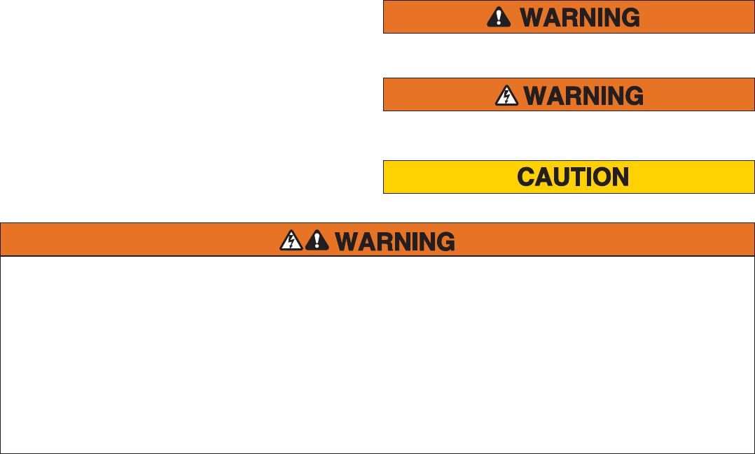
Safety Symbol and Signal Word Review
When you see these Safety Symbols and Signal Words on
the following pages, they will alert you to the possibility of
serious injury or death if you do not comply with the warnings
that accompany them. The hazard may come from something
mechanical or from electric shock. Read the warnings carefully.
When you see this Signal Word on the following pages, it will alert
you to the possibility of damage to your property or product if you
do not comply with the cautionary statements that accompany it.
Read them carefully.
MECHANICAL
ELECTRICAL
3
PRE-INSTALL NETWORK PROGRAMMINGINSTALL ACCESS CONTROLINTRODUCTION
INTRODUCTION
Carton Inventory ..................................................................... 4
Tools Needed .......................................................................... 4
Dimensions ............................................................................. 5
System Specifi cations ............................................................. 5
Wire Specifi cations ................................................................. 6
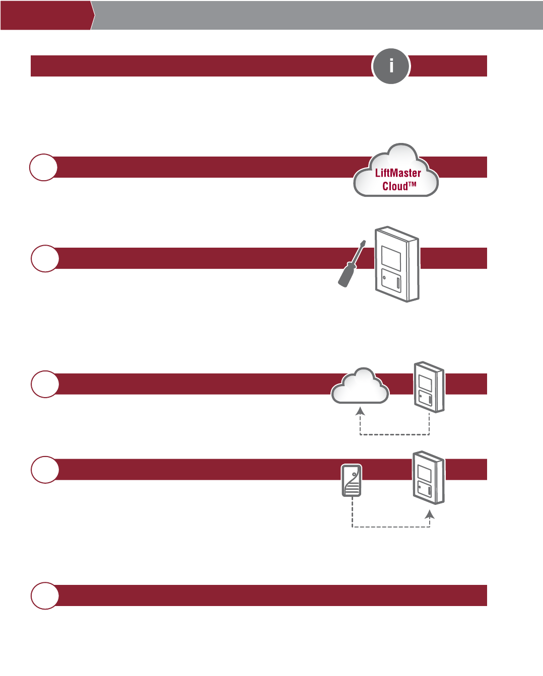
PRE-INSTALL
1
Internet Service ....................................................................... 7
SIP Provider ............................................................................ 7
Setup a LiftMaster Cloud Account ........................................... 7
INSTALL
2
Remove Knockouts ................................................................. 8
Mount the Controller ............................................................... 9
Controller Overview ............................................................... 10
Power/Internet Board Overview ............................................ 11
Door Board Overview ............................................................ 12
Install the Ground ................................................................. 14
Connect Power ...................................................................... 15
NETWORK
3
Connect Internet ................................................................... 16
Validate Setup ....................................................................... 16
ACCESS CONTROL
4
Gate Access (Wired) ............................................................. 17
Gate Access (Wireless) ......................................................... 18
Door Access .......................................................................... 19
Wiegand Proximity Reader .................................................... 20
Wiegand Output .................................................................... 21
Postal Lock ........................................................................... 22
Loop Detector Board ............................................................. 23
Programming ........................................................................ 24
Wiring Diagram ....................................................................25
Repair Parts .........................................................................26
Accessories .......................................................................... 26
Confi guration Sheet .............................................................27
Legal Disclaimers ................................................................ 28
Warranty ...............................................................................29
PROGRAMMING
5
4
Tools Needed
• Assorted Screwdrivers
• Precision Screwdrivers
• 1/4" Nut Driver
• Multimeter
• Wire Fish Tape
• Bits for Hammer Drill Bits for Drill/Driver
• Drill Screw Bit
• Wire Strippers
• Wire Cutters
• Assorted Pliers
• Flashlight
• Drill/Driver
• RJ45 Crimping Pliers
• Measuring tape
• Work Gloves
• Conduit Bender
• Conduit Cutter/Reamer
• Hack Saw
• Center Punch Tool
• Hammer
• 7/64" Drill Bit
PROVIDED (NOT SHOWN)
• Hardware for Camera Kit
• Installation Manual
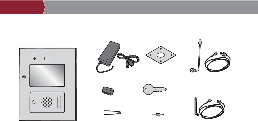
Controller
Carton Inventory
PRE-INSTALL NETWORK PROGRAMMINGINSTALL ACCESS CONTROLINTRODUCTION
Power Supply
Gooseneck Gasket
Keys (2)
Ferrite Core
S10K30MOV
(Metal Oxide Varistor)(4)
1N4005 Diode Kit (4)
Radio Antenna (Security+ 2.0®)
and Cable
Wi-Fi® Antenna and Cable
5
System Capacity People: 50,000 / Activity Buffer: 500,000
Supply Voltage 12Vdc, 5A, Class 2, Level VI (Power Supply 100-240VAC, 50/60Hz, 1.2A,
HK Yinghuiyuan Group YHY-12005000)
Operating Current 2.0 Amps - Without Accessories
Surge Suppression EFT: 2 Kv Power Line, ESD: 15 Kv Hbm / 8Kv Direct / 200V Mm
Controller Operating Temperature Range - 29°C to 54°C (-20°F to 130°F)
- 35°C to 65°C (-31°F to 151°F) Ambient Capability
Enclosure Stainless Steel
Storage and Shipping Temperature Range -40°C To 65°C (-40°F to 149°F)
Wiegand Inputs (4) 26Bit, 30Bit, 12V, 250mA Power Output (Per Input)
4 Primary and 4 Auxiliary Relay Outputs SPDT, Rated Load 3A at 30VDC
Accessory Compatibility Refer to the accessory page for compatible accessories
Network Compatibility RJ-45 Wired Ethernet
Wi-Fi® Compatibility 802.11 a/b/g/n
Wi-Fi® Range Up to 500 feet (152.4 m), Open Air/Line-of-Sight (range will vary depending on
obstructions)
Built-in LiftMaster Passport Receiver Security+ 2.0®
Wireless Communication to Gate Operator Up to 750 feet (228.6 m), Open Air/Line-of-Sight (range will vary depending on
obstructions), Compatible with LiftMaster Security+ 2.0® gate operators
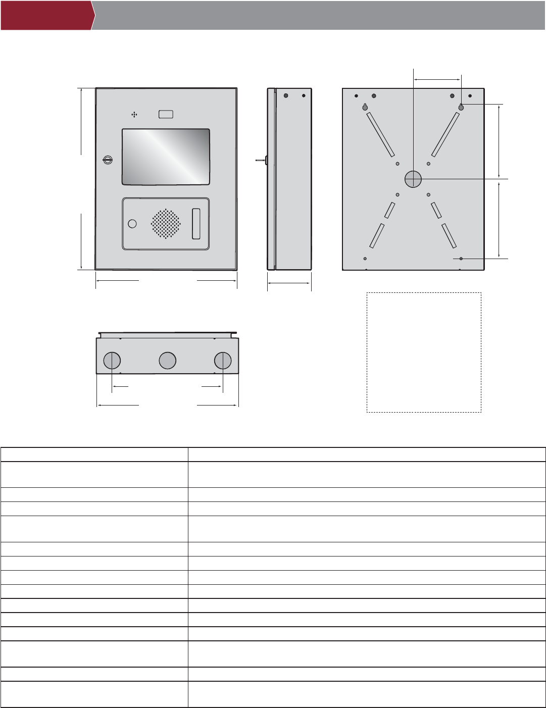
Dimensions
System Specifi cations
18" (45.7 cm)
14" (35.6 cm)
4-1/4" (10.8 cm)
FRONT VIEW SIDE VIEW BACK VIEW
BOTTOM VIEW
10-7/8" (25.4 cm)
14" (35.6 cm)
E = Electrical Wiring
P = Pedestal Mount
S = Surface Mount
R = Radio Antenna
W = Wi-Fi® Antenna
4-3/4" (10.2 cm)
7-13/32" (17.8 cm) 7-11/16" (17.8 cm)
PRE-INSTALL NETWORK PROGRAMMINGINSTALL ACCESS CONTROLINTRODUCTION
RW
RR
WW
SS
SS
PP
PP
E
EE
E

6
Wire Specifi cations
Use this chart to pull wires in preparation of your installation.
DESCRIPTION OF WIRE RUN WIRE SPECIFICATION MAXIMUM RUN DISTANCE
Power Wire, secondary DC output 2-Conductor 14 AWG
2-Conductor 16 AWG
2-Conductor 18 AWG
Up to 60 feet (18.3 m)
Up to 37 feet (11.3 m)
Up to 24 feet (7.3 m)
Local Area Network (LAN)
CAT 5/6 Network Cable
8-Conductor, 24 AWG Twisted pair 328 feet* (100 m)
Grounding the Chassis 12 AWG Copper 12 feet (3.7 m)
Door Strike 2-Conductor 18-22 AWG Shielded 100 - 250 feet (30.5 - 76.2 m)
Magnetic Lock 2-Conductor 18-22 AWG 50 - 125 feet (15.2 - 38.1 m)
Dry Contact Closure (Most Gate Operators) 2-Conductor 18-24 AWG Shielded 500 - 2500 feet (152.4 - 762 m)
Exit Request (REX) 2-Conductor 18-24 AWG 500 feet (152.4 m)
Supervised Input 2-Conductor 18-24 AWG 500 feet (152.4 m)
Wiegand/Proximity Readers 7-Conductor 18-22 AWG Shielded 500 feet (152.4 m)
Postal Lock Box 2-Conductor 18-24 AWG 250 - 1000 feet (76.2 - 304.8 m)
NOTE: Main power supply and control wiring MUST be run in separate conduits. Conduits must be UL approved for low and high
voltage. Refer to the NEC for additional wiring requirements.
Always provide power from a dedicated source. Plug provided transformer into an outlet wired to its own 10 Amp minimum circuit
breaker. This will prevent two problems:
• Other equipment cannot introduce spikes, noise, surges or dips into the power circuit that will affect the system.
• The system’s operation will not be affected if any other equipment develops a short circuit across the power line.
* CAT 5/6 NETWORK CABLE NOTES:
• For outdoor distances exceeding 140 feet (42.7 m), a UL497 compliant primary surge protector MUST be installed at
the controller.
• Distances exceeding 328 feet (100 m) can be accommodated with additional hardware. Contact Technical Support for more
information.
PRE-INSTALL NETWORK PROGRAMMINGINSTALL ACCESS CONTROLINTRODUCTION

7
Phone.com is the preferred SIP provider. Visit Phone.com/liftmaster to set up an account.
SIP service provider:
SIP domain:
SIP port (usually 5060):
SIP username:
SIP password:
CP# for Controller:
1Internet Service
The controller MUST be configured with the proper network settings to operate.
NETWORK
Internet service provider:
Wi-Fi Network Name:
Wi-Fi Password:
Automatic IP addressing: DHCP (preferred setting)
OR
Static IP Addressing: (NOTE: Write down the following for future reference: IP, Netmask, Gateway, Primary, Secondary, Server Port)
(example: sip.phone.com)
(example: 12345)
(example: s98hn&@f!idjs)
PRE-INSTALL NETWORK PROGRAMMINGINSTALL ACCESS CONTROLINTRODUCTION
(located on inside of the controller door and on the display when powered up)
2SIP Provider
3Setup a LiftMaster Cloud Account
NOTE: If you have an existing MyQ® account, your LiftMaster Cloud account will have the same
password.
1. If you do not have a LiftMaster Cloud Account, call LiftMaster Customer Care at 800.323.2276 to
activate a LiftMaster Hosted Cloud Service account.
2. You will get a welcome email from LiftMaster. Accept the invitation and register your account.
3. You will get a second email to activate your account.
4. Login to your account.
5. Set up your site and add residents and credentials (refer to the available Help in LiftMaster Cloud).
6. Continue with the installation of the controller in this manual.
8
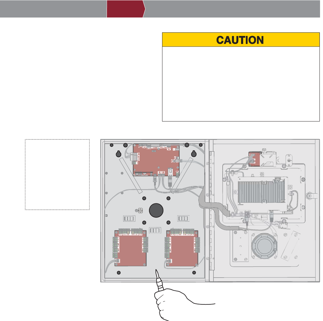
1Remove Knockouts
To prevent damage to the controller from moisture or water:
• DO NOT install during rain. Internal components MUST be
kept free from of water and moisture.
• BEFORE opening the front cover of the controller, remove
ANY accumulated water from the top of the controller.
To prevent damage to ANY internal components:
• DO NOT attempt to remove the knockouts with a hammer.
Banging on the knockouts may result in shock to the circuit
boards, which could cause permanent damage.
1. Turn the key clockwise and open the controller.
2. Identify which knockouts need to be removed
based on your application.
3. Use a center punch tool to remove the knockouts.
NOTE: Be careful when removing the knockouts to
avoid damaging the controller components.
PRE-INSTALL NETWORK PROGRAMMINGINSTALL ACCESS CONTROLINTRODUCTION
E = Electrical Wiring
P = Pedestal Mount
S = Surface Mount
R = Radio Antenna
W = Wi-Fi® Antenna
RR
W
SS
SS
PP
PP
E
W
9
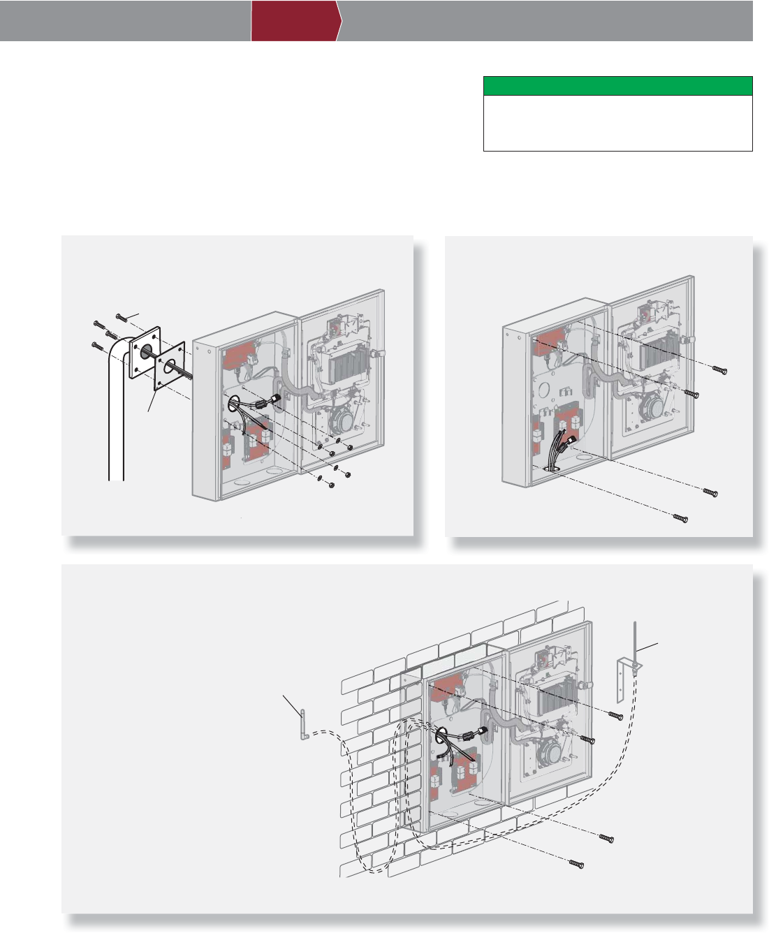
1. Attach the goose-neck gasket (provided) if mounting to a goose-neck.
2. Mount the controller securely to a fl at surface or pedestal with
appropriate hardware taking care to route wiring through appropriate
knockouts. NOTE: Ensure the cover can fully open to allow access after
the installation is complete.
Mount Controller
2DO
Make sure the controller is properly sealed
to prevent damage to the controller from
moisture.
PRE-INSTALL NETWORK PROGRAMMINGINSTALL ACCESS CONTROLINTRODUCTION
Pedestal Mount
1/4" x 1-1/2" Ribbed Neck
Security Bolt (4)
Goose-neck
Gasket
Surface Mount
Flush Mount
Flush Mount
Wi-Fi® Antenna
Radio Antenna
IMPORTANT: For fl ush
mount applications it may
be necessary to mount
the antennas remotely.
Optional antenna cable
kits are available for
remote antenna mounting
(refer to accessories).
Make sure you run the
cables for the remote
antennas before
mounting the controller.
10
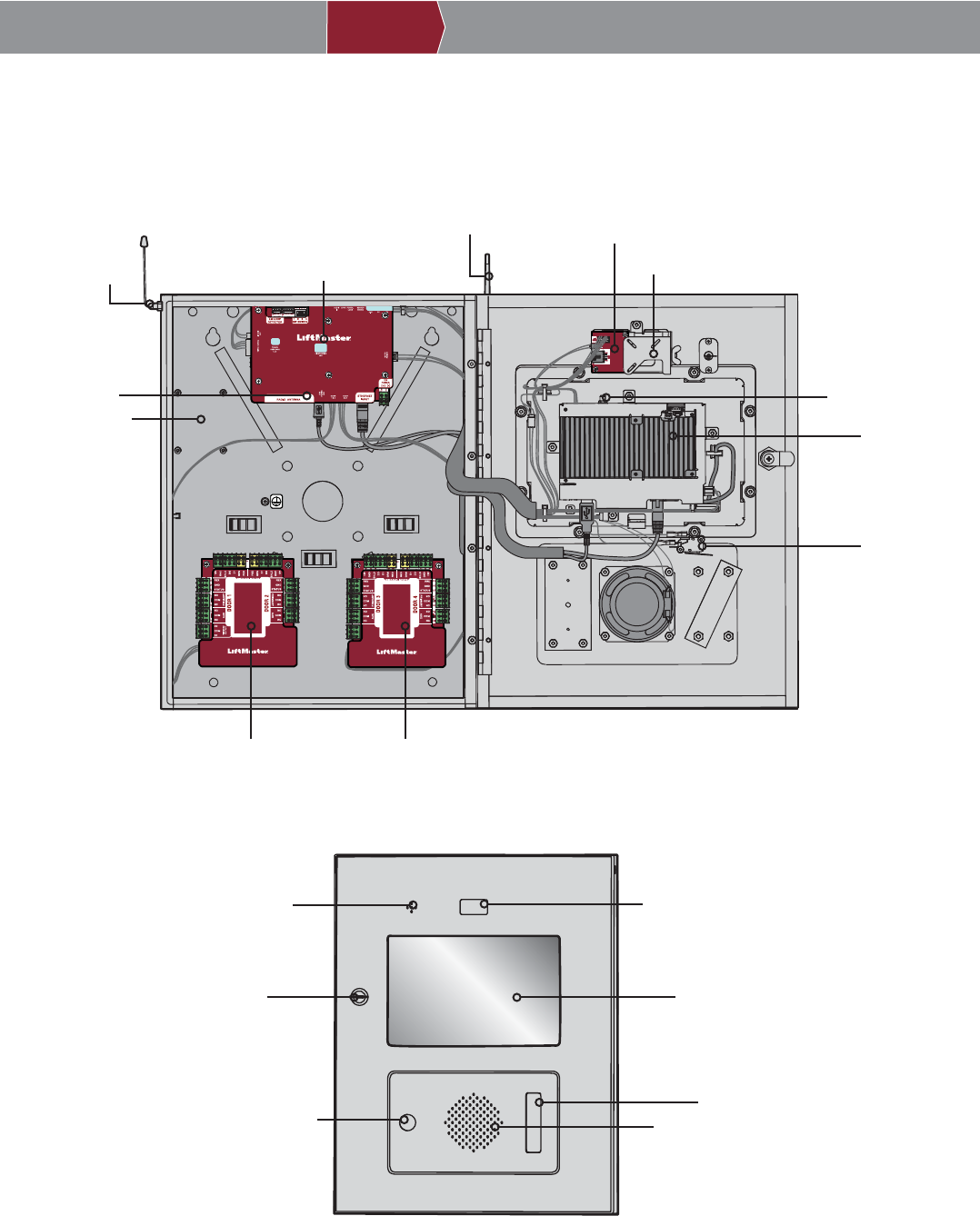
Controller Overview
ON
POWER/INTERNET BOARD
SENSOR BOARD
CONTROL BOARD
DOOR BOARD 1
(Doors 1 & 2)
LOOP DETECTOR
BOARD MOUNTING
LOCATION
CAMERA MOUNTING BRACKET
RADIO ANTENNA
Wi-Fi® ANTENNA
POSTAL LOCK
SWITCH
DISPLAY (TOUCHSCREEN)
SPEAKER
LOCK
POSTAL LOCK
LOCATION
PROXIMITY READER LOCATION
CAMERA LOCATION
MICROPHONE
RADIO ANTENNA
CONNECTION Wi-Fi® ANTENNA
CONNECTION
DOOR BOARD 2
(Doors 3 & 4)
PRE-INSTALL NETWORK PROGRAMMINGINSTALL ACCESS CONTROLINTRODUCTION
3
11
PRE-INSTALL NETWORK PROGRAMMINGINSTALL ACCESS CONTROLINTRODUCTION
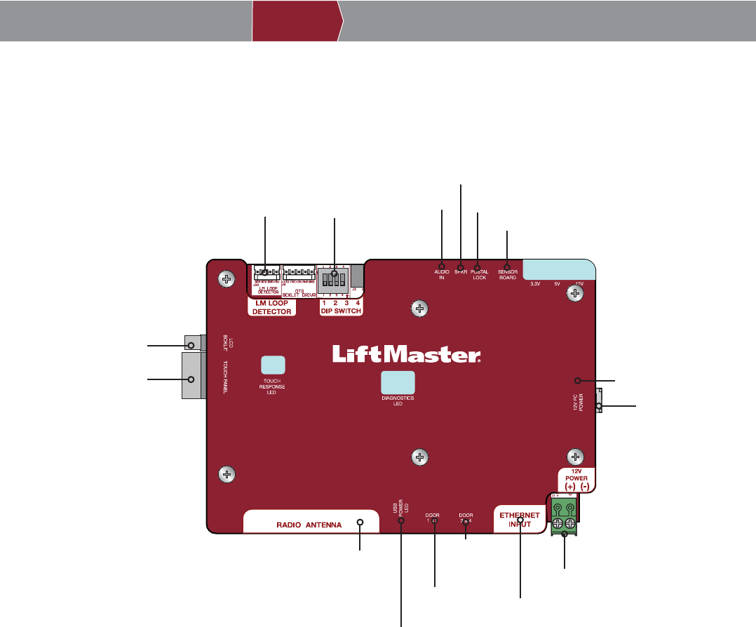
4Power/Internet Board Overview
ON
Display Backlight
Display (Touch)
RADIO ANTENNA
Connection to Control Board
Door Board 1
Door Board 2
ETHERNET
POWER
Power Connection
for Control Board
Auxiliary Power (not used)
Sensor Board
Postal Lock
Speaker
Audio
Dip Switches
(not used)
LOOP BOARD
12
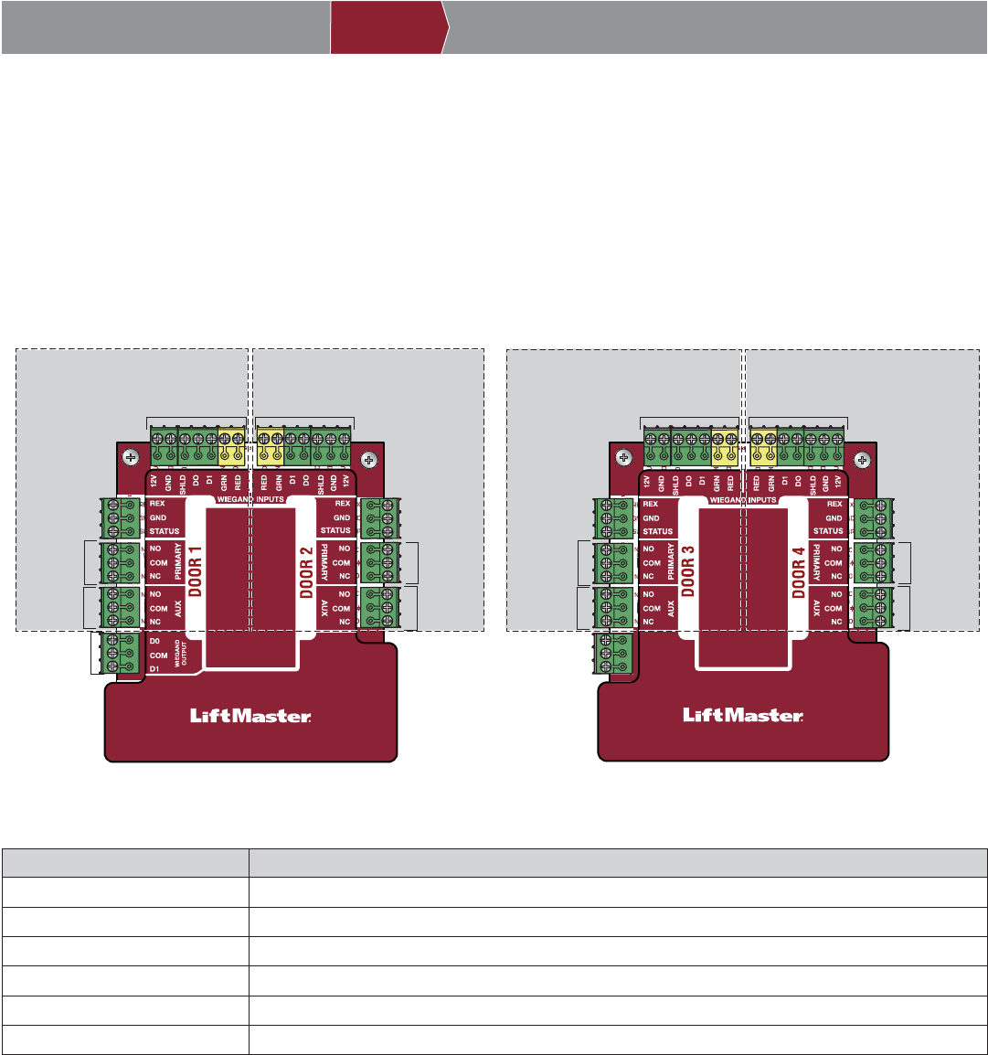
DOOR BOARD 1 DOOR BOARD 2
Door 1 Door 2
WEIGAND INPUT
PRIMARY
RELAY
AUXILIARY
RELAY
PRIMARY
RELAY
AUXILIARY
RELAY
REQUEST
TO EXIT
WEIGAND
OUTPUT
WEIGAND INPUT
REQUEST
TO EXIT
Door 3 Door 4
WEIGAND INPUT
PRIMARY
RELAY
AUXILIARY
RELAY
PRIMARY
RELAY
AUXILIARY
RELAY
WEIGAND INPUT
STATUS STATUS
STATUSSTATUS
NOT USED
REQUEST
TO EXIT
REQUEST
TO EXIT
Door Board Overview
The ACXL has a combination of access control inputs/outputs on the Door Boards that work in conjunction to control up to 4
access points.
INPUT/OUTPUT USED FOR
Wiegand Input Proximity Readers, RFID Receiver, and Keypads
Request to Exit External Free Exit Loop Detectors, Push Buttons, and Proximity Sensors
Status Door Sensors, Supervised Gate Operators, and EOL (End of Line) Wiring
Primary Relay Gate Operators, Door Strikes, and Maglocks
Auxiliary Relay Alarm Bypass, Maglocks, and Lights
Wiegand Output 26 Bit Access Granted Activity for integration with third party systems
PRE-INSTALL NETWORK PROGRAMMINGINSTALL ACCESS CONTROLINTRODUCTION
5
13
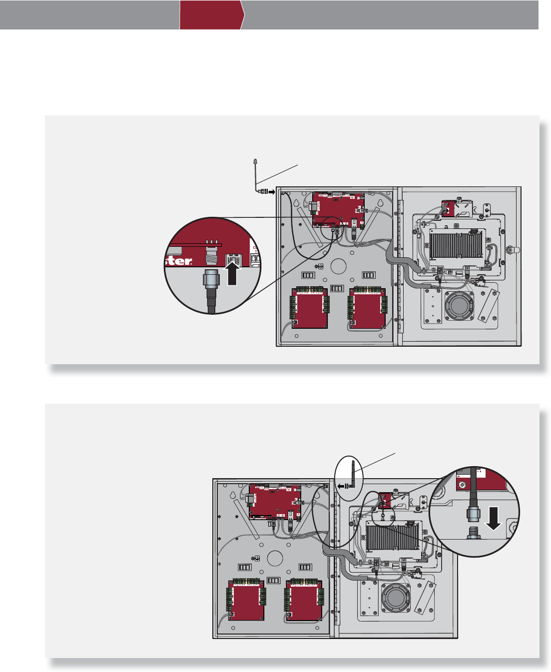
Install Antennas
6
PRE-INSTALL NETWORK PROGRAMMINGINSTALL ACCESS CONTROLINTRODUCTION
The radio antenna and Wi-Fi® antennas must be a minimum of 8 inches (20 cm) apart. Install the antennas on opposite sides
of the controller. Optional antenna cable kits are available for remote antenna mounting (refer to accessories).
Security+ 2.0® Radio Antenna (if applicable)
Used for transmitters and wireless gate communication.
1. Secure the radio
antenna to the desired
knockout on the
controller.
2. Connect the radio
antenna cable to the
Power/Internet Board
as shown.
Wi-Fi® Antenna (if applicable)
Used for Wi-Fi® Internet.
1. Secure the Wi-Fi® antenna to
the desired knockout on the
controller with the provided
gasket, washer, and nut.
2. Connect the Wi-Fi® antenna
cable to the control board as
shown.
ON
Radio Antenna
Power/Internet Board
ON
Wi-Fi® Antenna
Control Board
14
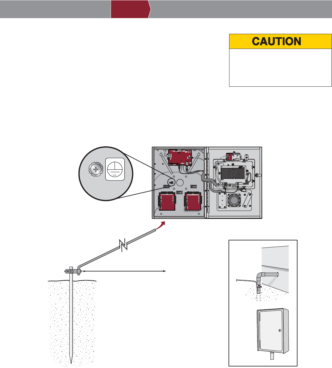
7Install the Ground
IMPORTANT: An earth ground rod is strongly recommended and should be no
further than 12 feet (3.7 m) from the controller and use a minimum of 12 gauge
wire in most cases. The type and length of earth ground rods vary by region.
Contact the AHJ (Authority Having Jurisdiction) in the municipality where you
plan to install the controller for correct grounding materials and installation
procedures.
1. Connect the ground wire (12 AWG or larger) to the controller ground lug.
2. Run the wire from the controller to suitable earth ground.
NOTE: Shield connections on boards should not be connected to ground lug.
ON
Ground wire
12 AWG minimum
Earth ground rod
Other ground sources within
12 feet of access control panel
Ground to
existing
electrical
system
Electrical
panel
Ground to
metallic cold
water pipe
12 feet (3.7 m) maximum
NOTE: Keep ground wire as
straight as possible.
Check national
and local codes
for proper depth
Typical ground
Ground Connection
To AVOID damaging gas, power or
other underground utility lines,
contact underground utility locating
companies BEFORE digging.
PRE-INSTALL NETWORK PROGRAMMINGINSTALL ACCESS CONTROLINTRODUCTION
15
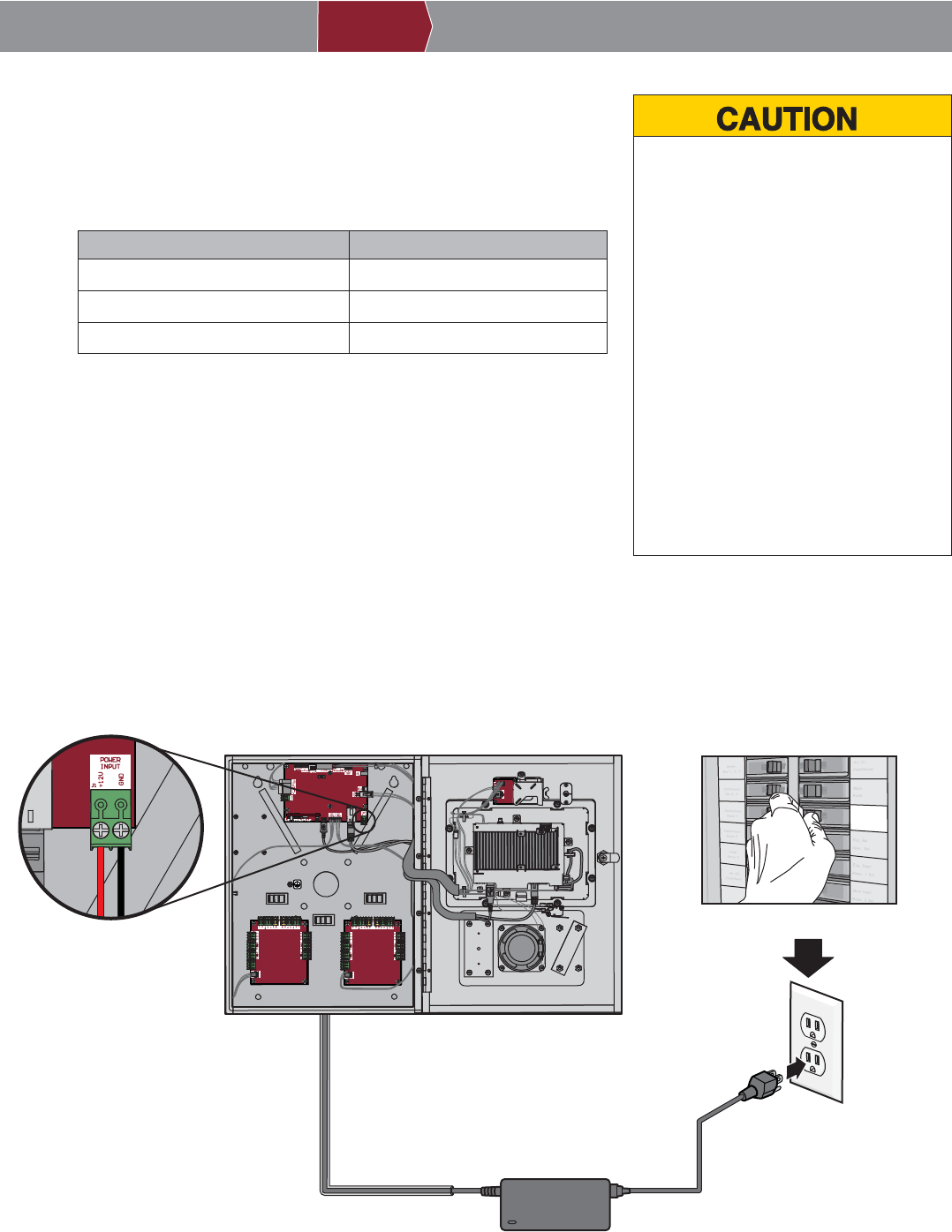
Connect Power
8• DO NOT use ANY power supply other
than those supplied with your controller.
• DO NOT power electronic strikes and
latches with the same power supply
used to power the access control panel;
doing so will cause DAMAGE to the
controller. Use ONLY a UL listed burglar
alarm or access control system to
power electronic strikes and latches.
• DO NOT connect the power supply to a
switched outlet or otherwise controlled
AC outlet.
• DO NOT connect the power supply to
the 120 Vac outlet until ALL wiring is
completed.
• Install the transient noise suppression
device (MOV) supplied with the
controller for AC powered devices and
Diode for DC powered devices.
The outlet for the controller MUST be an external dedicated 120 Vac outlet
located within 60 feet (18.3 m) cable run of the controller. This outlet
should be wired back to its own 10 Amp minimum circuit breaker.
1. Connect 14-18 AWG wire to the stripped secondary DC output wires on
the power supply. Black is negative and red is positive.
2. Remove the PWR INPUT terminal block from the Power/Internet Board.
3. Connect the power supply wires to the PWR INPUT terminal block (red
to +12V and black to GND). Reattach the terminal block to the
Power/Internet Board.
4. Plug the power supply into a 120 Vac outlet after all connections have
been made.
NOTE: The green LED on the door board will blink and the green LED
on the Power/Internet Board will light solid when powered up. The
controller will display the LiftMaster logo while booting up. When boot
up is complete, the user interface will appear.
5. Close the controller door.
PRE-INSTALL NETWORK PROGRAMMINGINSTALL ACCESS CONTROLINTRODUCTION
Dedicated 10 Amp Minimum Circuit
120 Vac
Dedicated Outlet
ON
Power Supply
POWER INPUT
Power/Internet Board
NOTE: If the power supply is installed outdoors,
the power supply must have its own approved
NEMA 4 Rated weatherproof electrical enclosure.
Use conduit from the power supply enclosure to
the controller enclosure.
WIRE SPECIFICATION MAXIMUM RUN DISTANCE
14 AWG Up to 60 Feet (18.3 m)
16 AWG Up to 37 Feet (11.3 m)
18 AWG Up to 24 Feet (7.3 m)