Chamberlain Group The 8439 AXCL Operator User Manual Product Literature 20161004 v1 6 ACXL Manual 2
Chamberlain Group Inc, The AXCL Operator Product Literature 20161004 v1 6 ACXL Manual 2
Contents
- 1. Product Literature_20161004_v1 - 6 ACXL Manual_1
- 2. Product Literature_20161004_v1 - 6 ACXL Manual_2
Product Literature_20161004_v1 - 6 ACXL Manual_2
16
1Connect Internet
The controller can connect to the Internet with LAN (wired) or with Wi-Fi® (wireless). Make sure you are in the Admin Mode
before you connect to the Internet. If you are not in Admin Mode, touch the upper left-hand corner of the display. Follow the
instructions according to your application.
PRE-INSTALL NETWORK PROGRAMMINGINSTALL ACCESS CONTROLINTRODUCTION
On the display, select each tab in Admin Mode to validate setup
(network, inputs, outputs, etc.). Once you have validated the setup,
exit Admin Mode.
Validate Setup
2
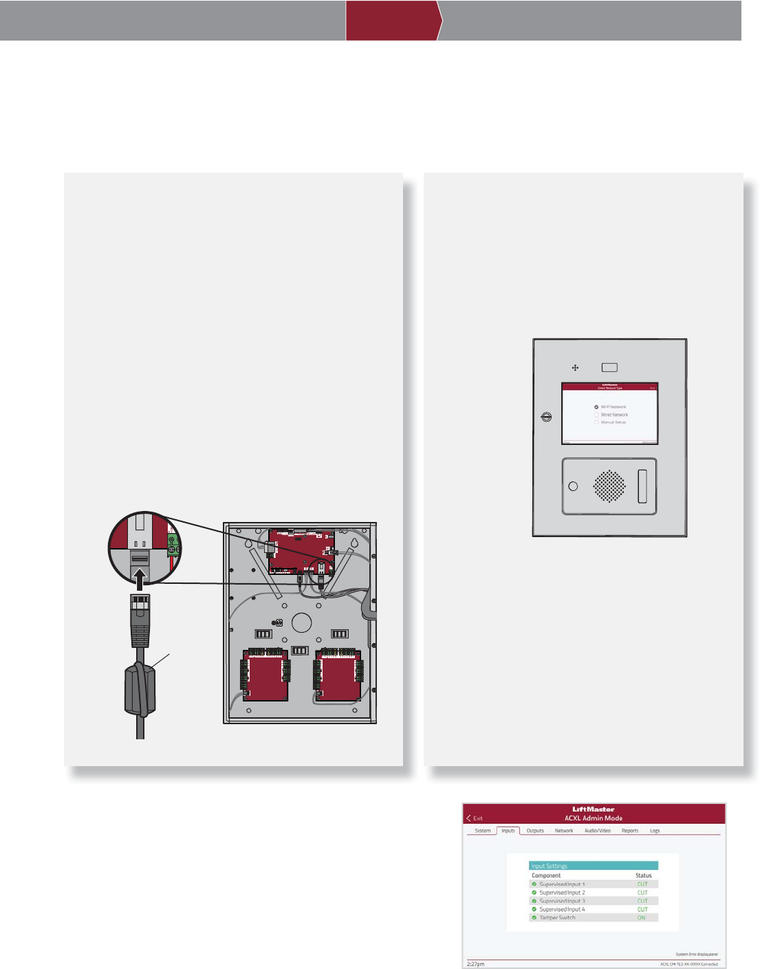
OPTION 1 Connect with LAN (wired)
The Local Area Network (LAN) port is a 10/100 Ethernet
interface with an RJ45 jack for connecting the controller
to a LAN in order for it to gain connectivity to the Internet.
Use a straight, (i.e., non-crossover) cable to connect to
a local hub, switch or router. Connect the Power/Internet
Board to a LAN functionality is a supplementary feature.
1. Connect an Ethernet cable from your LAN to the LAN
port on the Power/Internet Board. When connected
properly, the green and amber LED on the Ethernet
port will light/fl icker. If the green LED is not lit, check
the connections on the controller and the Ethernet
hub.
2. On the display, select Wired Network if dynamic
confi guration (DHCP) is desired or select Manual
Setup for a static IP address.
OPTION 2 Connect through Wi-Fi® (Wireless)
1. On the display select Wi-Fi Network.
2. Select the network the controller will use.
3. Enter the password for the network.
4. Select Login.
ON
LAN
on Internet/Power Board
Ferrite Core
17
PRE-INSTALL NETWORK PROGRAMMINGINSTALL ACCESS CONTROLINTRODUCTION
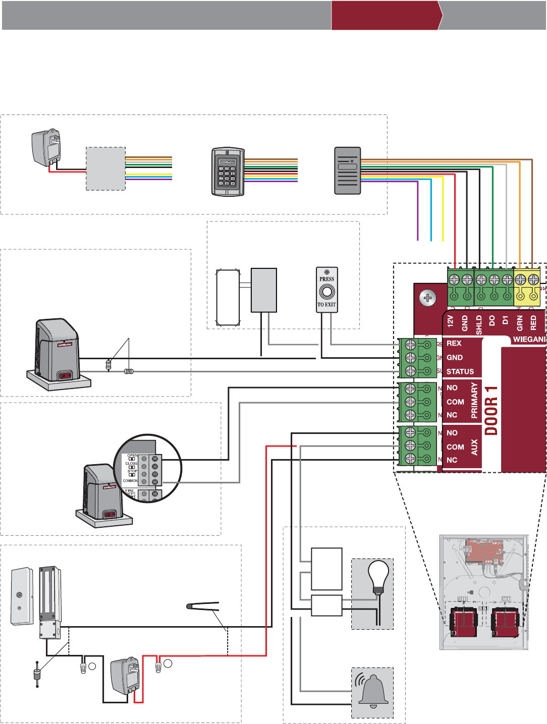
Gate Access (Wired)
Disconnect power BEFORE making electrical connections. Below is an example of a wiring setup for gate access. Gate access can
be wired to Door 1, 2, 3, or 4 on the Door Boards. LiftMaster® Security+ 2.0® gate operators can also be programmed to communicate
wirelessly instead of using a wired connection (refer to the following page).
NOTE: The length of the unshielded
wires should be kept to a minimum to
avoid electrical noise.
PUSH
BUTTON
GATE OPERATOR
(connect to closed limit switch)
MAGLOCK
RED LED - brown
GREEN LED - orange
DATA 1 - white
DATA 0 - green
SHIELD - shield
GROUND - black
12Vdc - red
not used - yellow
not used - blue
not used - purple
PROXIMITY READER
OR
KEYPAD
OR
EOL (End of Line)
Resistor (1k ohm)
EXTERNAL FREE EXIT
LOOP DETECTOR
For DC Power:
Install a 1N4005
diode or equivalent
Use 18-22 AWG
Model MG1300
Power for Maglock
(Not Provided)
DO NOT use the power
supply for the controller
For AC Power:
Install a Siemens S10K30MOV
(Metal Oxide Varistor) or equivalent
REQUEST TO EXIT
GROUND
STATUS
NORMALLY OPEN
COMMON
COMMON
NORMALLY CLOSED
+
–
NORMALLY CLOSED
COMMON
OR
DOOR 1, 2, 3, or 4
REQUEST TO EXIT
WEIGAND
STATUS
PRIMARY RELAY
AUXILIARY RELAY
GATE OPERATOR
COMMON
OPEN
NORMALLY OPEN
ALARM BYPASS
LIGHT
NORMALLY OPEN
COMMON
LOAD
LINE
AUXILIARY RELAY
OR
NEUTRAL
LiftMaster® Security+ 2.0® gate
operators can be programmed
to communicate wirelessly
instead of using a wired
connection. Refer to the
following page.
(Not applicable for wireless gate operator connections.)
RFID RECEIVER
with wiegand output
Power for RFID RECEIVER
(Not Provided)
DO NOT use the power
supply for the controller
NOTE: DO NOT
run high voltage
power within
the ACXL
enclosure.
Isolation
Relay
Low
Voltage
Power
Supply
NOTE: For KPR2000
keypad, wire the pink and
black (ground) wires together.
18
PRE-INSTALL NETWORK PROGRAMMINGINSTALL ACCESS CONTROLINTRODUCTION
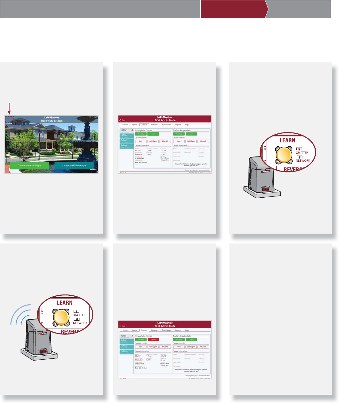
Gate Access (Wireless)
For use with LiftMaster® Security+ 2.0® gate operators.
1 Enter Admin Mode
Touch the upper left-hand corner of
the controller display to enter Admin
Mode.
2 Select Outputs and Relay
Select the Outputs tab. Then select the
desired relay on the left-hand side (1
through 4).
3 Press LEARN button on gate
operator
Press and release the LEARN button
on the primary operator. The green
XMITTER LED will light. NOTE: The
operator will time out of programming
mode after 180 seconds.
4 Press LEARN button on gate
operator again
Press and release the LEARN button
again on the primary operator. The
yellow NETWORK LED will light.
5 Select LEARN on display
Select the LEARN button on the
display and the Learn button will go
from green to red. The gate operator
and the controller will beep and the
NETWORK LED on the gate operator
will turn off indicating programming is
successful.
6 Validate
Validate functionality by selecting Test
Relay on the controller display.
19
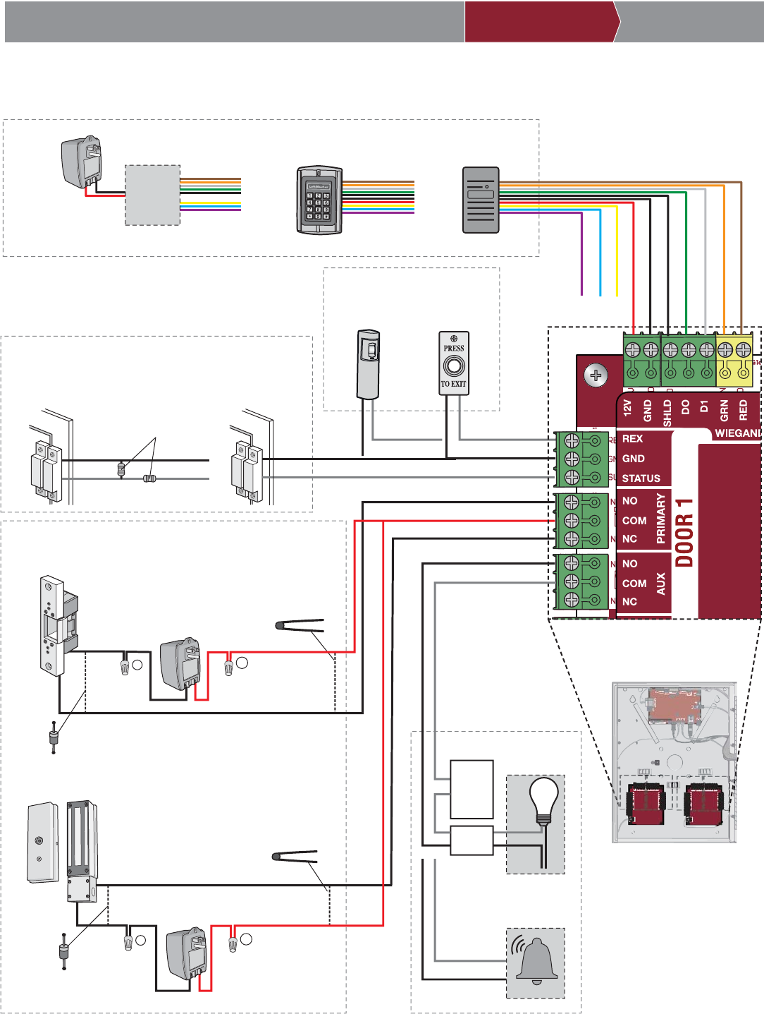
PUSH
BUTTON
DOOR SENSOR
(SUPERVISED)
DOOR STRIKE
MAGLOCK
DOOR SENSOR
(NON-SUPERVISED)
OR
EOL (End of Line) Resistor
(1k ohm)
PROXIMITY
SENSOR
For DC Power:
Install a 1N4005
diode or equivalent
Use 18-22 AWG
Model MG1300
Power for Maglock
(Not Provided)
DO NOT use the power
supply for the controller
For AC Power:
Install a Siemens S10K30MOV
(Metal Oxide Varistor) or equivalent
Use 18-22 AWG
For AC Power:
Install a Siemens S10K30MOV
(Metal Oxide Varistor) or
equivalent
For DC Power:
Install a 1N4005
diode or equivalent
Power for Door Strike
(Not Provided)
Model HES(R) 1006CLB(R)
REQUEST TO EXIT
GROUND
SUPERVISED
NORMALLY OPEN
COMMON
NORMALLY CLOSED
NORMALLY OPEN
COMMON
+
–
NORMALLY OPEN
COMMON
+
–
NORMALLY CLOSED
COMMON
OR
OR
REQUEST TO EXIT
SUPERVISED (DOOR STATUS)
PRIMARY RELAY
ALARM BYPASS
NORMALLY OPEN
COMMON
AUXILIARY RELAY
OR
DOOR 1, 2, 3, or 4
NOTE: The length of the unshielded
wires should be kept to a minimum to
avoid electrical noise.
RED LED - brown
GREEN LED - orange
DATA 1 - white
DATA 0 - green
SHIELD - shield
GROUND - black
12Vdc - red
not used - yellow
not used - blue
not used - purple
PROXIMITY READER
OR
KEYPAD
OR
WEIGAND
RFID RECEIVER
with wiegand output
Power for RFID RECEIVER
(Not Provided)
DO NOT use the power
supply for the controller
LIGHT
LOAD
LINE
NEUTRAL
NOTE: DO NOT
run high voltage
power within
the ACXL
enclosure.
Isolation
Relay
Low
Voltage
Power
Supply
NOTE: For KPR2000
keypad, wire the pink and
black (ground) wires together.
Door Access
Disconnect power BEFORE making electrical connections. Below is an example of a wiring setup for door access. Door access can be
wired to Door 1, 2, 3, or 4 on the Door Boards.
PRE-INSTALL NETWORK PROGRAMMINGINSTALL ACCESS CONTROLINTRODUCTION
20
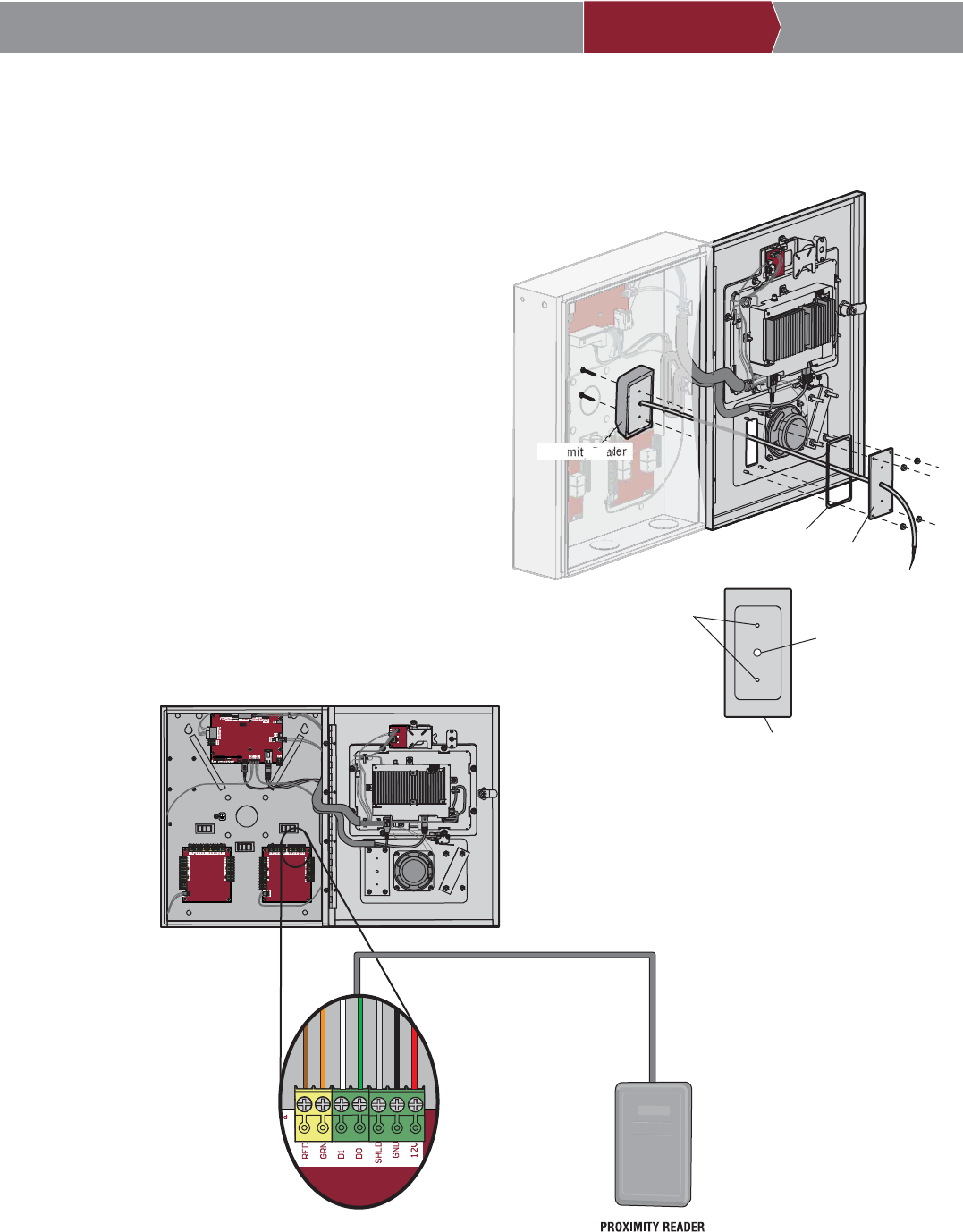
Wiegand Proximity Reader
The controller is designed specifi cally for the HID PROX-POINT+ MINI READER proximity reader to be mounted on the faceplate.
1. Disconnect power.
2. Remove the mounting plate and gasket from the controller.
3. Use a bench vise with soft jaws to hold the mounting plate and
drill a hole for the cable with a 5/16" drill bit.
4. Drill two mounting holes with a 7/64" drill bit. Make the
threads using the self-tapping screws provided with the
HID reader. NOTE: Thread the screw and remove. Clean the
mounting hole thoroughly until the entire thread is made.
5. Reinstall the gasket and mounting plate onto the controller.
6. Install the proximity reader and secure with the screws.
7. Apply silicon around the cable hole.
8. The proximity reader can be wired to any of the 4 Wiegand
Inputs on the door control boards. Insulate any unused wires
from the controller to prevent a short. (Refer to instructions
supplied with your Wiegand device for more information.)
9. Connect power.
10. Refer to LiftMaster Cloud for programming.
PRE-INSTALL NETWORK PROGRAMMINGINSTALL ACCESS CONTROLINTRODUCTION
Gasket Mounting Plate
Proximity Reader
Mounting
Holes Cable
Hole
Mounting Plate
ON
WEIGAND
INPUT
brown
orange
white
green
shield
black
red
Card Reader is wired to WEIGAND INPUT
NOTE: The length of the unshielded
card reader wires should be kept to
a minimum to avoid electrical noise.
Use 18-24 AWG
21
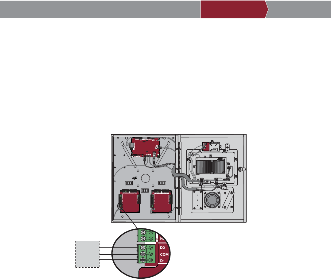
Wiegand Output
ON
Data 0
Common
Data 1
DOOR BOARD 1
Third Party Access System
Wiegand Input
Disconnect power BEFORE making electrical connections. The controller offers a Wiegand output capable of 26 bit transmission of the
following data:
• Success Call with access granted by the resident. The controller will provide a LMC specifi ed facility code followed by the Directory
Code of the resident that granted access.
And/Or
• Successful access through Entry Code. The controller will provide a LMC specifi ed facility code followed by the successful Entry
Code.
The two facility codes should be different to prevent duplicate code transmission with the Wiegand Output.
PRE-INSTALL NETWORK PROGRAMMINGINSTALL ACCESS CONTROLINTRODUCTION
22
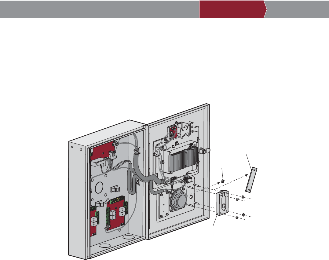
Postal Lock
PRE-INSTALL NETWORK PROGRAMMINGINSTALL ACCESS CONTROLINTRODUCTION
1. Remove the nuts, retainer bracket, and plug. Discard the retainer bracket and plug.
2. Install the postal lock reusing the nuts previously removed.
The postal lock switch is wired from the factory.
Postal Lock
Plug
Retainer Bracket
23
PRE-INSTALL NETWORK PROGRAMMINGINSTALL ACCESS CONTROLINTRODUCTION
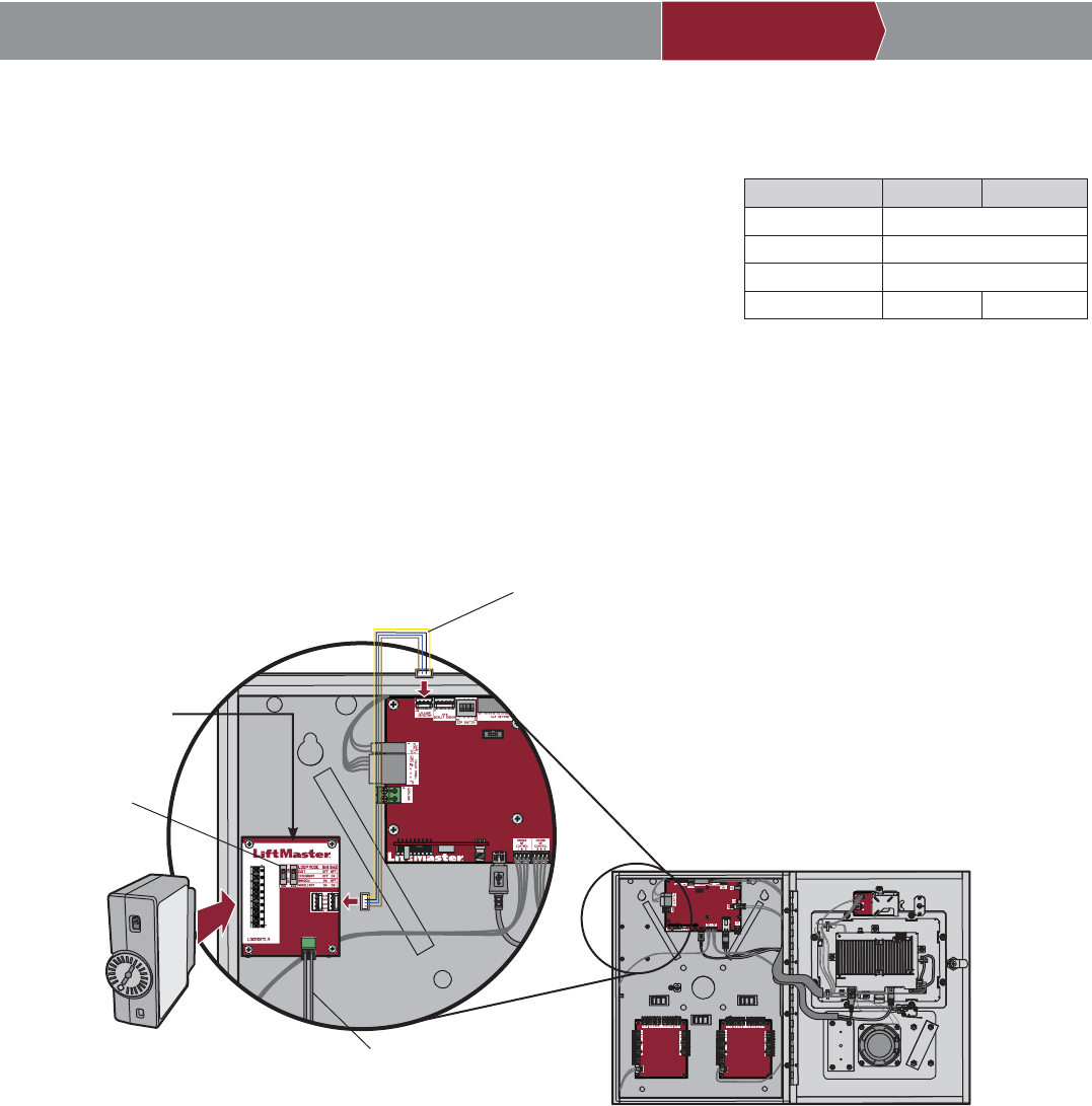
Loop Detector Board
Disconnect power BEFORE making electrical connections. The Loop Detector Board
provides Auto Call functionality that is available through the auxiliary switch setting.
1. Secure the Loop Detector Board to the standoffs in the controller with the provided
screws.
2. Connect the wire harness from the Loop Detector Board to the Power/Internet Board.
3. Connect the loop wires to the input on the Loop Detector Board.
4. Plug in the loop detector (model LOOPDETLM).
5. Set both switches on the Loop Detector Board to ON (auxiliary setting).
Refer to LiftMaster Cloud for programming.
ON
ON
Plug-in Loop Detector
Model LOOPDETLM
Wire Harness
Loop Wiring
LOOP MODE SW1 SW2
EXIT Not supported
INTERRUPT Not supported
SHADOW Not supported
AUXILIARY ON ON
Switches
LOOP DETECTOR BOARD
24
PRE-INSTALL NETWORK PROGRAMMINGINSTALL ACCESS CONTROLINTRODUCTION
1Create a Facility
1. On the left navigation bar, click
Facilities, and click Add facility.
2. Enter the following information:
• Facility name
• Directory code length
(required fi eld)
• Address
• City/town
• State
• Zip code
• Country (required fi eld)
• Time zone (required fi eld)
• Contact information- This
is required. The contact
is typically the property
manager
3. Click Save.
3 Add Door(s)
NOTE: Door 1 is automatically
created and associated to the Door
1 relay. This step is to confi gure
Relay 2.
1. On the left navigation bar, click
Facilities or Dashboard.
2. Select the facility.
3. Click on the Controllers tab
and select the controller you
want to add the door to.
4. Click on the Doors tab next to
the Controller Settings.
5. Select Relay 2 to control the
door.
6. Click Add Door.
7. Enter the name of the door.
8. Click Save and Close.
2 Add New Controller(s)
The Control Panel # is required to
add a controller to a facility. The
Control Panel # is located on the
product label.
1. On the left navigation bar, click
Facilities or Dashboard.
2. Select the name of the facility
where the new controller will be
added.
3. Click on the Controllers tab.
4. Click Add New Controller.
5. Enter the Control Panel # (CP#)
and the name of the controller.
6. Click Save. The Controller will
appear on the list, a browser
refresh may be necessary.
4 Add Schedule(s)
1. On the left navigation bar, click
Schedules.
2. Select the name of the facility.
3. Click Add Schedule and enter
schedule information:
• Name of schedule
• Description of schedule
• Do not select an Enabling
Group unless you want a
member of the enabled group
to activate the schedule
when they enter their entry
code. NOTE: The schedule
is not applied or activated
until a member of the group
accesses the property using a
credential or pin.
4. To select a range of hours and
days, click on the hour and day
and drag to create the schedule
or you may click on individual
hours and days.
5. Add holidays and exceptions.
6. Click Save.
5 Create Group(s)
1. On the left navigation bar, click
Groups.
2. Select the facility you are
creating a group for.
3. Click Add Group.
4. Enter a name for the new
group.
5. Select the Status (active or
suspended).
6. Click People and click Add
users+.
7. Select the people for the group
by clicking on the + next to the
name of the person.
8. Add the zones for this group
by, click Zones and click Add
Zones+.
9. Select the zones by clicking on
the + next to the name of zone.
10. Click Save.
24
7 Add a Credential
1. On the left navigation bar, click Credentials.
2. Select the facility.
3. Click Add credential.
4. Select the Type: Card or transmitter.
5. Select the Format: Standard 26 bit or 30-Bit Wiegand.
6. Enter the card or transmitter information:
• Card number
• Offset
• Facility code
• Vendor code (30-Bit Wiegand ONLY)
7. Click Save.
NOTE: If adding multiple credentials, click Bulk load, enter the fi rst and last number in the series, the offset of the fi rst
card, and the facility code.
8 Add People
1. On the left navigation bar, click
People.
2. Select the facility.
3. Click Add Person.
4. From the Profi le tab, Personal,
enter the following information:
• Email (optional)
• First and last name
• Role (use -- in most cases)
5. In Contact, select the Do not
disturb schedule check box if
desired.
6. In Contact, enter the following
information:
• Phone numbers
• Address, city, state, and zip
code
7. Click, Save.
8. Click the Vehicle Information
tab, enter vehicle information if
desired.
9. Click Add a new vehicle.
10. Enter the vehicle information:
• Year
• Make
• Model
• State
• License plate number
• Color
11. Click Add vehicle to add another
vehicle to the person’s profi le.
12. Click, Save.
13. Setup Facility Access. If the
person is to be called by the
system you will need to set up the
Facility Access Directory.
a. From the add people screen,
click the Facility Access tab.
b. Enter the directory information,
click Verify. If you want the
system to automatically
assign a directory code, click
Generate Code.
c. Enter a PIN, click Verify.
If you want the system to
automatically assign a PIN,
click Generate PIN. Select
Credentials for this person by
clicking in the blank space in
the Cards/Transmitters fi eld
and select one a credential.
14. Set Access
a. If you want to set activation
and expiration dates, click the
Calendar icon for activation,
select the date for activation.
Click the Calendar icon for
expiration, select the date you
want their access to expire.
b. Select the Groups(s) for this
person, click in the blank
space in the Access Groups
fi eld.
15. Click Save.
6 Create Zone(s)
1. On the left navigation bar,
click Facilities or Dashboard.
2. Select the facility.
3. Click on the Zones tab.
4. Click Add New Zone.
5. Enter name of the zone.
6. Click Doors.
7. Click Add doors+ and click on
the + next to the name of the
door.
8. Click on Groups.
9. Click on Add Groups+ and
select the Groups for the new
zone.
10. Select the schedule from the
drop-down list.
11. Click Save.
Login to your LiftMaster Cloud Account then follow the steps below.
25
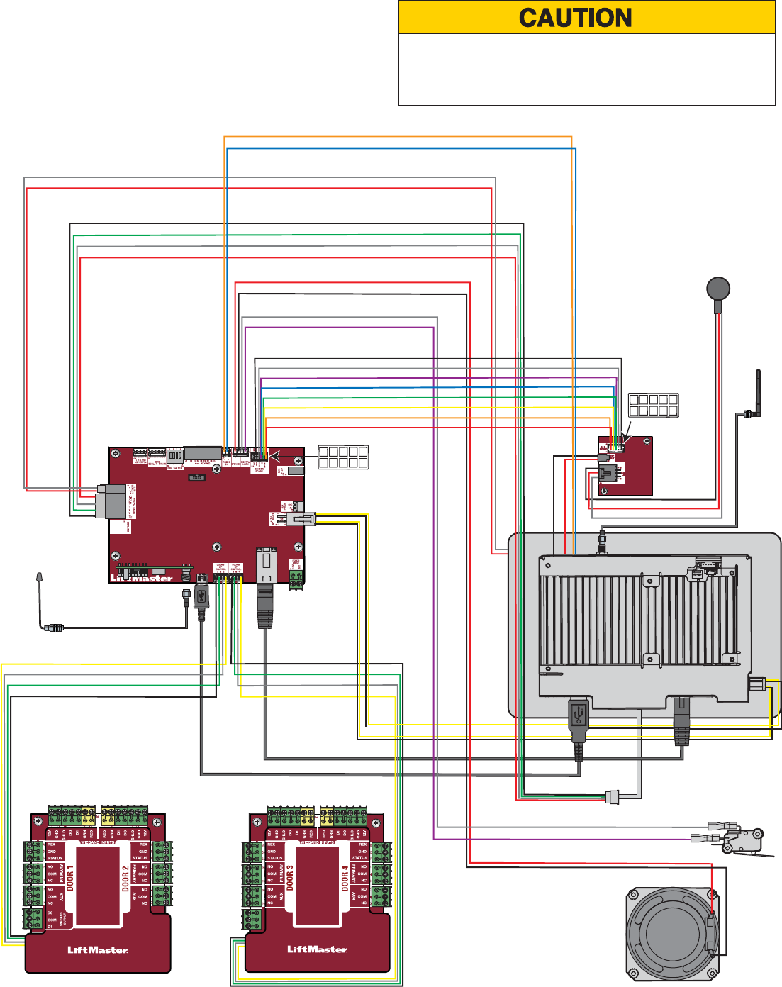
ON
POWER/INTERNET BOARD
DOOR BOARD DOOR BOARD
SENSOR
BOARD
SPEAKER
yellow
white
green
black yellow
white
green
black
black
green
white
red
black
red
purple
white
red
white
black
white
purple
blue
green
yellow
orange
red
red
blue
orange
1 - Red
2 - Orange
3 - Yellow
4 - Green
5 - Blue
6 - Purple
7 - Not used
8 - White
9 - Black
10 - Not used
1
2
3
4
5
6
7
8
1 - Red
2 - Orange
3 - Yellow
4 - Blue
5 - Green
6 - Purple
7 - Not used
8 - White
9 - Black
10 - Not used
1
2
3
4
5
6
7
8
9
10
MICROPHONE
black
red
black
white
POSTAL LOCK SWITCH
Wi-Fi®
ANTENNA
RADIO ANTENNA
9
10
Wiring Diagram
Not responsible for conflicts between the information listed in
the wiring diagram and the requirements of your local building
codes. The information is for suggested use ONLY. Check your
local codes BEFORE installation.

26
Accessories
ITEM PART NUMBER
Back Box and Trim Kit ACXLTK
ACXL Hood Kit ACXLHOOD
Card Reader Multi-class SE RP10 Mini Mullion LMMC-MINI
Radio Antenna Extension (15 foot) 86LM
Wi-Fi Antenna Extension (15 foot) WIFIEXT
Wiegand Keypad/Proximity Reader KPR2000
Wiegand Proximity Reader PPLX
Loop Detector Kit (Complete with: Loop Detector Board, Plug-In Loop
Detector [model LOOPDETLM], and wire harness) TBD
All LiftMaster® MyQ®/UL325 compatible gate operators
Passport 3-Button Visor Remote Control MAX PPV3M
Passport 3-Button Mini Remote Control MAX PPK3M
Passport 3-Button Mini Proximity Remote Control MAX PPK3PHM
Passport Lite 1-Button Visor Remote PPLV1-X*
Passport Lite 1-Button Key Chain Remote PPLK1-X*
Passport Lite 1-Button Mini Proximity Remote PPLK1PH-X*
Repair Parts
* Available in 10 and 100 packs, replace X with 10 or 100
COMING SOON
PLEASE CONTACT LIFTMASTER FOR ALPHA TEST REPAIR PART INFORMATION:
1.877.232.7987

27
Confi guration Sheet
Record device information and confi guration settings below.
Controller Name:
NOTE: Any user of the system is subject to the terms outlined in the product EULA.
Notes:
DEVICE CONFIGURATION:
DOOR 1 DOOR/GATE NAME:
INPUTS WIEGAND REX STATUS
EOL (Y / N)
OUTPUTS
PRIMARY RELAY AUXILIARY RELAY
N.O. N.C. N.O. N.C.
Notes:
DOOR 2 DOOR/GATE NAME:
INPUTS WIEGAND REX STATUS
EOL (Y / N)
OUTPUTS
PRIMARY RELAY AUXILIARY RELAY
N.O. N.C. N.O. N.C.
Notes:
DOOR 3 DOOR/GATE NAME:
INPUTS WIEGAND REX STATUS
EOL (Y / N)
OUTPUTS
PRIMARY RELAY AUXILIARY RELAY
N.O. N.C. N.O. N.C.
Notes:
DOOR 4 DOOR/GATE NAME:
INPUTS WIEGAND REX STATUS
EOL (Y / N)
OUTPUTS
PRIMARY RELAY AUXILIARY RELAY
N.O. N.C. N.O. N.C.
Notes:

28
Legal Disclaimers
Federal Communications Commission (FCC) Compliancy
This equipment has been tested and found to comply with the limits for a Class B digital device, pursuant to Part 15 of the FCC
Rules. These limits are designed to provide reasonable protection against harmful interference in a residential installation or when the
equipment is operated in a commercial environment. This equipment generates, uses and can radiate radio frequency energy and, if
not installed and used in accordance with the instruction manual, may cause harmful interference to radio communications. However,
there is no guarantee that interference will not occur in a particular installation. If this equipment does cause harmful interference to
radio or television reception, which can be determined by turning the equipment off and on, the user is encouraged to try to correct the
interference by one or more of the following measures:
• Increase the distance between the equipment and receiver.
• Connect the equipment to a circuit other than the one to which the receiver is connected.
• Consult the dealer for help.
Canada-Underwriters Laboratories (C-UL) Compliancy
For C-UL Listed applications, the controller shall be installed in accordance with Part 1 of the Canadian Electrical Code.
Documentation Disclaimer and Restrictions
Information in this document is subject to change without notice and does not represent a commitment on the part of LiftMaster. For the
most up-to-date information, visit www.LiftMaster.com.
This document and the data herein shall not be duplicated, used or disclosed to others for procurement or manufacturing, except
as authorized with the written permission of LiftMaster. The information contained within this document or within the product itself
is considered the exclusive property of LiftMaster. All information in this document or within the hardware and software product
themselves is protected by the copyright and/or other intellectual property laws of the United States.
UL 294 Access Control Unit Level 1
NOTICE: To comply with FCC and/or Industry Canada (IC) rules, adjustment or modifi cations of this digital device are prohibited. THERE ARE NO USER SERVICEABLE PARTS. Any changes or modifi cations not expressly
approved by the party responsible for compliance could void the user’s authority to operate the equipment.
This device complies with Part 15 of the FCC rules and IC License-Exempt RSS Standard(s). Operation is subject to the following two conditions: (1) this device may not cause harmful interference, and (2) this device must
accept any interference received, including interference that may cause undesired operation.
This Class B digital apparatus complies with Canadian ICES-003.
This device has been tested and found to comply with the limits for a Class B digital device, pursuant to part 15 of the FCC rules. These limits are designed to provide reasonable protection against harmful interference in
a residential installation. This equipment generates, uses and can radiate radio frequency energy and, if not installed and used in accordance with the instructions, may cause harmful interference to radio communications.
However, there is no guarantee that interference will not occur in a particular installation. If this equipment does cause harmful interference to radio or television reception, which can be determined by turning the equipment off
and on, the user is encouraged to try to correct the interference by one or more of the following measures:
- Reorient or relocate the receiving antenna.
- Increase the separation between the equipment and receiver.
- Connect the equipment into an outlet on a circuit different from that to which the receiver is connected.
- Consult the dealer or an experienced radio/TV technician for help.
- This device must be installed in a way where a minimum 8" (20 cm) distance is maintained between users/bystanders and device.
AVIS : Les règles de la FCC et/ou d’Industrie Canada (IC) interdisent tout ajustement ou toute modifi cation de ce récepteur. IL N’EXISTE AUCUNE PIÈCE SUSCEPTIBLE D’ÊTRE ENTRETENUE PAR L’UTILISATEUR. Tout
changement ou toute modifi cation non expressément approuvé par la partie responsable de la conformité peut avoir pour résultat d'annuler l'autorité de l’utilisateur de faire fonctionner l’équipement.
Ce dispositif est conforme à la partie 15 des règles de FCC et des normes Permis-Exemptes d’IC RSS. Son utilisation est assujettie aux deux conditions suivantes : (1) ce dispositif ne peut causer des interférences nuisibles, et
(2) ce dispositif doit accepter toute interférence reçue, y compris une interférence pouvant causer un fonctionnement non souhaité.
Cet appareil numérique de la classe B est conforme à la norme NMB-003 du Canada.
Ce dispositif a été mis à l’essai et déclaré conforme aux limites établies pour les dispositifs numériques de classe B, conformément à l’article 15 des règles de la FCC. Cette conformité a pour but de fournir une protection
raisonnable contre les interférences nuisibles dans une installation résidentielle. Cet équipement génère, utilise et peut émettre des fréquences radio et, s’il n’est pas installé et utilisé conformément aux instructions, causer des
interférences nuisibles aux communications radio. Cependant, il n’existe aucune garantie que des interférences ne se produiront pas dans une installation particulière. Si cet équipement provoque des interférences nuisibles à la
réception d’une diffusion sonore ou visuelle, ce qui peut être déterminé en l’allumant et en l’éteignant, l’utilisateur est invité à essayer de résoudre ce problème en prenant une ou plusieurs des mesures suivantes :
- Réorienter ou déplacer antenne de réception.
- Augmenter la distance entre l’équipement et le récepteur.
- Brancher l’appareil à une prise sur un circuit différent de celui du récepteur.
- Pour obtenir de l’aide, consulter le détaillant ou un radiotechnicien expérimenté.
- Ce dispositif doit être installé de manière à ce qu’une distance d’au moins 20 cm (8 po) soit maintenue entre les utilisateurs/passants et le dispositif.
29
Warranty
LiftMaster (“Seller”) warrants to the fi rst purchaser of this product, for the structure in which this product is originally installed, that it is
free from defect in materials and/or workmanship for a period of two years from the date of purchase.
The proper operation of this product is dependent on your compliance with the instructions regarding installation, operation,
maintenance and testing. Failure to comply strictly with those instructions will void this limited warranty in its entirety.
If, during the limited warranty period, this product appears to contain a defect covered by this limited warranty, call 1-800-528-2806
before dismantling this product. Then send this product, pre-paid and insured, to our service center for warranty replacement. Products
returned to Seller for warranty replacement, which upon receipt by Seller are confi rmed to be defective and covered by this limited
warranty, will be replaced (at Seller’s sole option) at no cost to you and returned pre-paid. Defective parts will be replaced with new or
factory-rebuilt parts at Seller’s sole option.
THIS LIMITED WARRANTY IS IN LIEU OF ANY OTHER WARRANTIES, EXPRESS OR IMPLIED, INCLUDING ANY IMPLIED WARRANTY
OF MERCHANTABILITY OR FITNESS FOR A PARTICULAR PURPOSE OR OTHERWISE, AND OF ANY OTHER OBLIGATIONS OR LIABILITY
ON SELLER’S PART. THIS LIMITED WARRANTY DOES NOT COVER NON-DEFECT DAMAGE, DAMAGE CAUSED BY IMPROPER
INSTALLATION, OPERATION OR CARE (INCLUDING, BUT NOT LIMITED TO ABUSE, MISUSE, FAILURE TO PROVIDE REASONABLE
AND NECESSARY MAINTENANCE, UNAUTHORIZED REPAIRS OR ANY ALTERATIONS TO THIS PRODUCT), LABOR CHARGES FOR
REINSTALLING A REPAIRED OR REPLACED UNIT, PROBLEMS RELATED TO INTERFERENCE, OR REPLACEMENT OF BATTERIES.
UNDER NO CIRCUMSTANCES SHALL SELLER BE LIABLE FOR CONSEQUENTIAL, INCIDENTAL OR SPECIAL DAMAGES ARISING
IN CONNECTION WITH USE, OR INABILITY TO USE, THIS PRODUCT. IN NO EVENT SHALL SELLER’S LIABILITY FOR BREACH OF
WARRANTY, BREACH OF CONTRACT, NEGLIGENCE OR STRICT LIABILITY EXCEED THE COST OF THE PRODUCT COVERED HEREBY.
NO PERSON IS AUTHORIZED TO ASSUME FOR US ANY OTHER LIABILITY IN CONNECTION WITH THE SALE OF THIS PRODUCT.
Some states do not allow the exclusion or limitation of consequential, incidental or special damages, so the above limitation or exclusion
may not apply to you. This limited warranty gives you specifi c legal rights, and you may also have other rights which vary from state to
state.

© 2016 LiftMaster
ALPHA All rights reserved.
Wi-Fi® is a registered trademark of Wi-Fi Alliance.