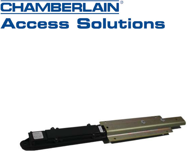
Chamberlain Group The OVX1 Radio activated locking device User Manual 114A3885 OverlockManual indd
Chamberlain Group Inc, The Radio activated locking device 114A3885 OverlockManual indd
User Manual

For Technical Support Please Call:
1-888-528-7826
www.chamberlainaccess.com
ACCESSMASTER OL1010 OVERLOCK
INSTALLATION MANUAL

Warning: Changes or modifi cations not expressly approved by the party responsible for
compliance could void the user’s authority to operate the equipment.
This equipment has been tested and found to comply with the limits for a Class B digital
device, pursuant to Part 15 of the FCC Rules. These limits are designed to provide reasonable
protection against harmful interference in a residential installation. This equipment generates,
uses, and can radiate radio frequency energy and, if not installed and used in accordance with
the instructions, may cause harmful interference to radio communications. However, there
is no guarantee that interference will not occur in a particular installation. If this equipment
does cause harmful interference to radio or television reception, which can be determined by
turning the equipment off and on, the user is encouraged to try to correct the interference by
one or more of the following measures:
Reorient or relocate the receiving antenna.•
Increase the separation between the equipment and receiver.•
Connect the equipment into an outlet on a circuit different from that to which the •
receiver is connected.
Consult the dealer or an experienced radio TV technician for help.•
This Class B digital apparatus complies with Canadian ICES-003.
Cet appareil numérique de la classe B est conforme à la norme NMB-003 du Canada.
To comply with FCC/IC RF exposure limits for general population/uncontrolled exposure,
the antenna(s) used for this transmitter must be installed to provide a separation distance
of at least 20 cm from all persons and must not be co-located or operating in conjunction
with any other antenna or transmitter.
RF Exposure
To comply with FCC/IC RF exposure requirements for mobile transmitting devices, this
transmitter should only be used or installed at locations where there is at least 20cm
separation distance between the antenna and all persons.
© 2008, The Chamberlain Group, Inc.
All Rights Reserved
114A3885
Overlock
Serial Number Unit Number Transceiver
Serial Number

Overlock
Serial Number Unit Number Transceiver
Serial Number
CARTON INVENTORY
Overlock device
Battery cover
(4) Lithium batteries
(4) Screws
(5) Pop Rivets
Spacers
Installation Kit (?)
CONTENTS
Overview................................................................................................... 1
Specifi cations ........................................................................................... 1
Battery Power .......................................................................................... 2
Tools Required.......................................................................................... 2
Assembly ................................................................................................. 2
Mounting the Overlock.............................................................................. 2
OL1000 Operation .................................................................................. 6
Troubleshooting ........................................................................................ 6
Warranty & Disclaimer ............................................................................. 7
iv
Overview
The Overlock device is a battery-powered, radio-actuated, locking device
that provides a positive stop to control unit access. An actuator is extended
until it sits against a closed door hasp, providing a positive lock that
effectively prevents the door from being opened.
The Overlock provides additional access and security control that integrates
with a Falcon XT access control system. This additional control helps to
protect vacant units from unauthorized use or vandalism and assists in
preventing access to units by delinquent users.
The overlock device provides automated overlocking of commercial doors.
The device offers two modes of operation:
Delinquent payment: Allows manager to overlock the customer’s
●
unit until the delinquent amount has been paid.
Vacant unit: Allows manager to secure a vacant unit to help prevent ●
vandalism and unauthorized use.
An opt-out function is included that allows the site manager to turn off any
or all of these options. Please refer to the Overlock Software Manual for
information on setting up each function.
Specif cations
Battery: 4 AA lithium, 1.5V
Temperature: -40° C to +85° C
Range: 500 ft Open Range maximum
Frequency: 903 to 928 Mhz ISM
Door and Hasp Types Supported: (For Beta)
Door Types: Janus 650
DBCI 2000
US Door 501/502
Hasp Types: Chateau C-DL-1 and
C-DL2 four bolt door latch
The overlock can be installed on both right-hand and left-hand door hasps.
9
Chamberlain Access Solutions shall have no liability for any death, injury,
or damage, however incurred, based on a claim that Chamberlain Access
Solutions Products failed to function. However, if Chamberlain Access
Solutions is held liable, directly or indirectly, for any loss or damage arising
under this limited warranty or otherwise, Chamberlain Access Solutions’s
maximum liability will not in any case exceed the purchase price of the
Product, which will be fi xed as liquidated damages and not as a penalty,
and will be the complete and exclusive remedy against Chamberlain
Access Solutions
Warning: The User should follow all installation, operation,
and maintenance instructions. The User is strongly advised to
conduct Product and systems test at least once each week. Changes
in environmental conditions, electric or electronic disruptions, and
tampering may cause the Product to not perform as expected.
Warning: Chamberlain Access Solutions warrants its Product to
the User. The User is responsible for exercising all due prudence and
taking necessary precautions for the safety and protection of lives and
property wherever Chamberlain Access Solutions Products are installed.
Chamberlain Access Solutions does not authorize the use of its Products
in applications affecting life safety.
Notice. Some Chamberlain Access Solutions products use 900Mhz
wireless technology. Other devices at the site such as cordless telephones
or alarm components may cause interference that will disrupt the operation
of the system or may be interfered with by the system. Chamberlain Access
Solutions assumes no liability for any problems caused by interference. It is
the sole responsibility of the user to identify and correct such problems.
8
WARRANTY & DISCLAIMER
Chamberlain Access Solutions warrants its products and equipment to
conform to its own specifi cations and to be free from defects in materials
and workmanship, under normal use and service, for a period of two
years from the date of shipment. Within the warranty period, Chamberlain
Access Solutions will repair or replace, at its option, all or any part of
the warranted product which fails due to materials and/or workmanship.
Chamberlain Access Solutions will not be responsible for the dismantling
and/or re-installation charges. To utilize this warranty, the customer must
be given a Return Goods Authorization (RGA) number by Chamberlain
Access Solutions The customer must pay all shipping costs for returning
the product.
This warranty does not apply in cases of improper installation, misuse,
failure to follow the installation and operating instructions, alteration,
abuse, accident, tampering, natural events (lightning, fl ooding, storms,
etc.), and repair by anyone other than Chamberlain Access Solutions. This
warranty does not warrant the replacement of batteries that are used to
power our products.
This warranty is exclusive and in lieu of all other warranties, expressed or
implied, including but not limited to the implied warranties of merchantability
and fi tness for a particular purpose. Chamberlain Access Solutions will
not be liable to anyone for any consequential or incidental damages for
breech of this warranty or any other warranties.
This warranty will not be modifi ed or varied. Chamberlain Access Solutions
does not authorize any person to act on its behalf to modify or vary this
warranty. This warranty applies to Chamberlain Access Solutions products
only. All other products, accessories, or attachments used in conjunction
with our equipment, including batteries, will be covered solely by their own
warranty, if any. Chamberlain Access Solutions will not be liable for any
direct, incidental, or consequential damage or loss whatsoever, caused by
the malfunction of product due to products, accessories, or attachments
of other manufacturers, including batteries, used in conjunction with our
products.
The customer recognizes that a properly installed and maintained security
system may only reduce the risk of events such as burglary, robbery,
personal injury, and fi re. It does not insure or guarantee that there will
be no death, personal damage, and/or damage to property as a result.
Chamberlain Access Solutions does not claim that the Product may not
be compromised and/or circumvented, or that the Product will prevent any
death, personal and/or bodily injury and/or damage to property resulting
from burglary, robbery, fi re, or otherwise, or that the Product will in all
cases provide adequate warning or protection.
Chamberlain Access Solutions products should only be installed by qualifi ed
installers. The customer is responsible for verifying the qualifi cations of the
selected installer.
1
Battery Power
Power for the unit is provided by four AA lithium batteries (included). The
lithium batteries supplied are maintenance-free batteries. Under normal
operating conditions these batteries should last for up to 2 years. When
the batteries need to be replaced, the system will alert the administrator.
To replace the batteries:
Remove the old batteries and replace with new lithium batteries.
1.
Dispose of the old batteries per local codes for hazardous waste.
2.
NOTE: Do not use alkaline batteries in the overlock. Alkaline batteries will result
in
greatly reduced battery life and system performance. Lithium batteries last up to
7 times longer than alkaline and will withstand outdoor temperatures that alkaline
batteries will not.
Tools Required
Drill
¼” drill bit
allen wrench (may change if new screw head is used)
Pop riveting tool for ¼” pop rivet
Marking pen
Ruler
Assembly
The only assembly required will be to insert the batteries and fasten the
battery cover after installation.
NOTE: If door alarms are installed on the door, ensure that they are installed on
the opposite side of the door hasp so they do not impede the movement of the
door and overlock after installation.
Set Up the OL1010
To program the overlock, the device must ‘learn’ the devices to
communicate
with. Devices must be manually learned before installation. To manually
learn overlocks to the transceiver:
After the transceiver is connected to the Falcon XT, press the
1.
function button on the transceiver (SW1) to put it into learn mode.
When the red LED is lit (not blinking) the transceiver is in learn
mode.
Insert the batteries in the overlock.
2.
Press the Learn button on the overlock (S2) to be learned. The LED
3.
on both the overlock and the transceiver will pulse while the device
is being learned. When the LED on the overlock goes out, the
device is learned. Learn all overlocks in this manner.
After all overlocks have been learned to the transceiver, press
4.
the function button on the transceiver and the LED will go off. The
transceiver is no longer in learn mode.

2
Mounting the Overlock
After overlocks have been learned they can be installed on the units.
During installation, keep track of the serial number of each overlock, the
unit number on which it is installed, and the serial number of the transceiver
to which it reports. This information will be needed when installing the
software. (The worksheets on pages 9-10 can be copied and used as
needed to keep track of device and unit assignments.)
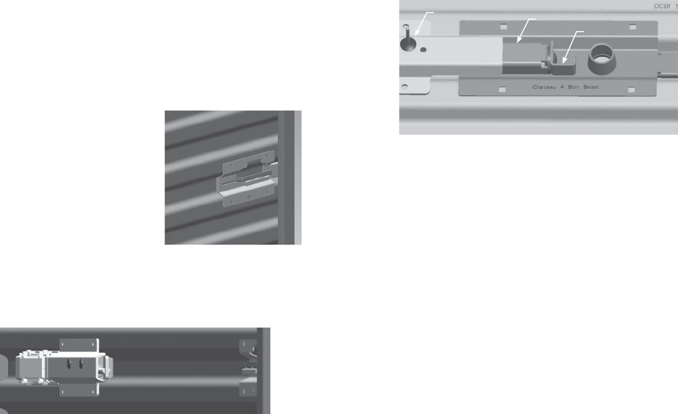
Use the following procedure to install the overlock device on a corrugated
rolling or swing door:
If the unit is unrented, ensure that 1.
the door is closed and the door
hasp is in the locked position.
(The unit may be rented with a
customer lock already installed.)
Test the actuator to ensure that 2.
it extends and retracts properly.
The overlock device should be
delivered from the factory with
the actuator extended and should
be in the extended position
before installation. To operate the
actuator, press the black tamper
switch once to extend and again to retract.
Position the overlock device in the door groove with the door hasp. 3.
(A customer lock may be present on the unit if the unit is currently
rented.)
7
After installation, the overlock and adapter should be positioned as 5.
follows.
Troubleshooting
Overlock service alerts are managed in the overlock management software.
In the software, go to Tools\Manage Overlocks to view and clear alerts.
.
Overlock Cover
Bracket
Lever

6
Add the cover bracket and the nylon or fl ange nut. Tighten until 2.
fi tted snugly using a 1/4”drive ratchet with extension and a 7/16”
socket.
When installation is complete, the adapter should be positioned as 3.
follows.
Install the overlock device using the previous mounting instructions.4.
Nylon or
Flange Nut
Cover
Bracket
Cover
Bracket
Overlock
3
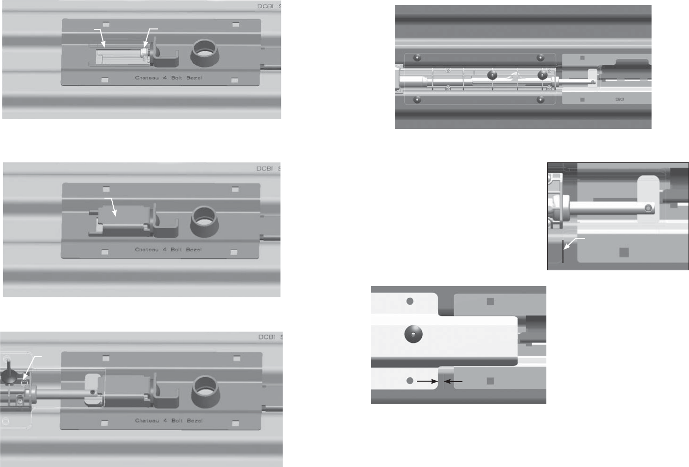
Slide the overlock toward the hasp until the end of the extended 4.
actuator touches the end of the hasp.
NOTE: The actuator will not be visible from the front as the mounting bracket
covers the actuator.
Using the edge of the mounting 5.
bracket as a guide, mark this
position on the door with the
marking pen.
Slide the overlock away from 6.
the hasp until there is a 1/4"
gap between the hasp and the
actuator. Mark this position using
the marking pen.
NOTE: The overlock device may
need to be shimmed to hold the
device tight against the door. If
spacers are used for shimming,
be sure to use them at all fi ve
rivet points. Not shimming a
door that requires it can severely
damage both the overlock and
the door.
Mark edge of mounting
bracket.
1/4"

4
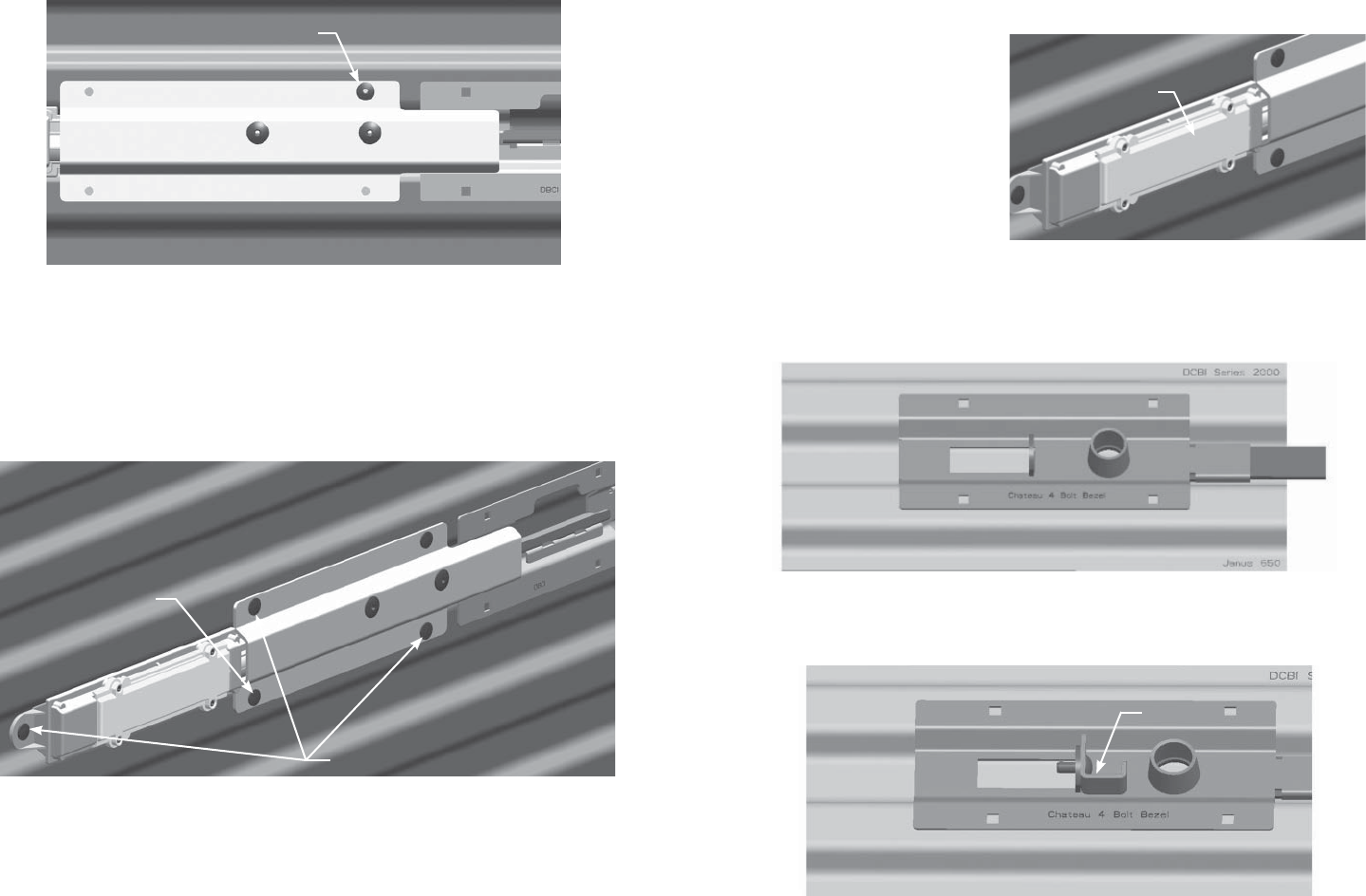
Hold the overlock in position tight against the door and drill a 1/4" 7.
hole in the door through the top right hole.
With the overlock still held tight in position, place a rivet through the 8.
hole and secure it using the pop rivet tool.
Drill a second hole in the door through the bottom left hole on the 9.
metal plate. Place a rivet through the hole and secure it using the
pop rivet tool.
Drill the remaining three holes in the overlock device. Place rivets in 10.
each of the three holes and secure using the pop rivet tool.
Drill hole in bottom left
hole and insert rivet.
Drill remaining 3 holes using the
overlock as a guide. Secure with
rivets.
Drill hole in top right
hole and insert rivet.
5
Test the actuator again after installation. Press the tamper switch 11.
(S3) located to the left of the battery case to retract the actuator
arm. The actuator should be in the retracted position after
installation.
Install the battery cover. 12.
Install all screws just
until each one holds.
Tighten down each
screw using a cross-
hatch pattern to prevent
binding of the screws.
Installing an Adapter
The standard overlock device is designed for use with Chateau C-DL-1 and
C-DL2 four bolt door latch door hasps. An adapter has been designed so that
the overlock can be used with the Chateau 4 bolt bezel latch hasp type.
Use the following procedure to install the adapter.
After installing the bezel latch, add the lever and the 1/4” x 3/4” 1.
carriage bolt.
Install battery cover.
Lever