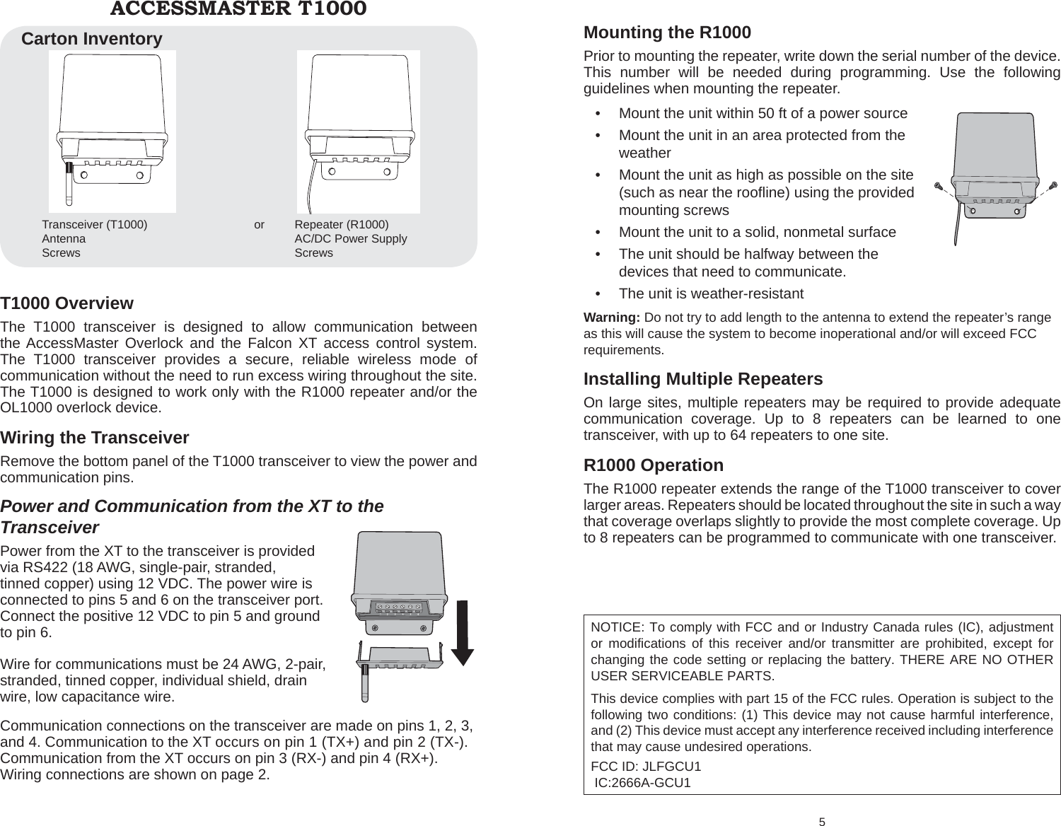
Chamberlain Wireless XCVR The T1000 is a transceiver that facilitates communication User Manual 114A3884 T1000 R1000 indd

Chamberlain Wireless Products Inc. The T1000 is a transceiver that facilitates communication 114A3884 T1000 R1000 indd

User Manual

6 For Technical Support Please Call: 1-888-528-7826www.chamberlainaccess.com© Chamberlain Access SolutionsAll Rights ReservedTroubleshootingRepeater service alerts are managed in the overlock management software. In the software, go to Tools\Manage Repeaters to view and  clear alerts.Low Battery IndicationThe battery power on the R1000 repeater is supervised by the Overlock Management Software. A low battery indication will generate an alert in the software, notifying the administrator.114A3884ACCESSMASTER T1000 TRANSCEIVER AND ACCESSMASTER R1000 REPEATER INSTALLATION MANUALBeta VersionNot for general release
T1000 Overview The T1000 transceiver is designed to allow communication between the AccessMaster Overlock and the Falcon XT access control system. The T1000 transceiver provides a secure, reliable wireless mode of communication without the need to run excess wiring throughout the site.  The T1000 is designed to work only with the R1000 repeater and/or the OL1000 overlock device.Wiring the TransceiverRemove the bottom panel of the T1000 transceiver to view the power and communication pins.Power and Communication from the XT to the TransceiverPower from the XT to the transceiver is provided via RS422 (18 AWG, single-pair, stranded, tinned copper) using 12 VDC. The power wire is connected to pins 5 and 6 on the transceiver port. Connect the positive 12 VDC to pin 5 and ground to pin 6.Wire for communications must be 24 AWG, 2-pair, stranded, tinned copper, individual shield, drain wire, low capacitance wire. Communication connections on the transceiver are made on pins 1, 2, 3, and 4. Communication to the XT occurs on pin 1 (TX+) and pin 2 (TX-). Communication from the XT occurs on pin 3 (RX-) and pin 4 (RX+). Wiring connections are shown on page 2.ACCESSMASTER T1000Transceiver (T1000)   orAntennaScrewsRepeater (R1000)AC/DC Power SupplyScrewsCarton Inventory5 Mounting the R1000Prior to mounting the repeater, write down the serial number of the device. This number will be needed during programming. Use the following guidelines when mounting the repeater.Mount the unit within 50 ft of a power source • Mount the unit in an area protected from the •  weatherMount the unit as high as possible on the site •  (such as near the roofl ine) using the provided mounting screwsMount the unit to a solid, nonmetal surface • The unit should be halfway between the •  devices that need to communicate.The unit is weather-resistant• Warning: Do not try to add length to the antenna to extend the repeater’s range as this will cause the system to become inoperational and/or will exceed FCC requirements.Installing Multiple RepeatersOn large sites, multiple repeaters may be required to provide adequate communication coverage. Up to 8 repeaters can be learned to one transceiver, with up to 64 repeaters to one site. R1000 Operation The R1000 repeater extends the range of the T1000 transceiver to cover larger areas. Repeaters should be located throughout the site in such a way that coverage overlaps slightly to provide the most complete coverage. Up to 8 repeaters can be programmed to communicate with one transceiver. NOTICE: To comply with FCC and or Industry Canada rules (IC), adjustment or modifications of this receiver and/or transmitter are prohibited, except for changing the code setting or replacing the battery. THERE ARE NO OTHER USER SERVICEABLE PARTS.This device complies with part 15 of the FCC rules. Operation is subject to the following two conditions: (1) This device may not cause harmful interference, and (2) This device must accept any interference received including interference that may cause undesired operations.FCC ID: JLFGCU1  IC:2666A-GCU1
4 R1000 Overview The R1000 repeater can be added to the T1000 system to extend the range of the T1000 transceiver up to 500 ft, depending on the conditions of the site. The R1000 repeater provides a secure, reliable wireless mode of communication without the need to run excess wiring throughout the site. The R1000 is designed to work only with the T1000 transceiver and the OL1000 overlock device.R1000 AssemblyRemove cover.1. Insert 4 lithium batteries 2. Replace the cover3. Wiring the RepeaterThe repeater must be connected to an AC/DC power supply. Remove the bottom panel of the repeater to view the power pins. For AC power: Connect the red and black wires to terminals 1 and 2. (With AC power, it doesn’t matter whether the red or black is connected to the + terminal, however, wire color use should be consistent throughout the site) For DC power:Connect the red wire to terminal 1 (DC+) Connect the black wire to terminal 3 (DC-)Set Up the R1000  To program the repeater, the device must ‘learn’ the devices to communicate with. Devices must be manually learned before installation. To manually learn repeaters to the transceiver:After the transceiver is connected to the Falcon XT, press the 1.  function button on the transceiver (SW1) to put it in learn mode. When the red LED is lit (not blinking) the transceiver is in learn mode.Press the Learn button on the repeater to be learned. The LED on 2.  both the repeter and the transceiver will pulse while the device is being learned. When the LED on the repeater goes out, the device is learned. Learn all repeaters in this manner.After all repeaters have been learned to the transceiver, press 3.  the function button on the tranceiver and the LED will go off. The transceiver is no longer in learn mode.ACCESSMASTER R10001 Communication ConnectionsPin Comm1 TX +2 TX -3 RX -4 RX +12 VDC 100 mAPin Power5 12 VDC6 GroundNOTE: Auxiliary power for peripheral devices is NOT provided on the transceiver. These devices must be powered separately.132456RX-RX+TX-TX+Ground+-13245612 VDC
2 Power and Communication from the Transceiver to the XTPower from the controller to the transceiver is provided via RS422 (18 AWG, single-pair, stranded, tinned copper) using 12 VDC. The power wire is connected to pins 5 and 6 on the transceiver port. Connect the positive 12 VDC to pin 5 and ground to pin 6.Wire for communications must be 24 AWG, 2-pair, stranded, tinned copper, individual shield, drain wire, low capacitance wire. Communication connections on the transceiver are made on pins 1, 2, 3, and 4. Communication to the XT occurs on pin 1 (TX+) and pin 2 (TX-). Communication from the XT occurs on pin 3 (RX-) and pin 4 (RX+). Wiring connections are shown on page 2.Set Up the T1000  After wiring is completed, push the learn button once to verify power. The LED will light if power is connected correctly. The LED will go off automatically after a few seconds. This will also automatically learn the transceiver to the Falcon XT.Mounting the TransceiverPrior to mounting the transceiver, write down the serial number of the device. This number will be needed during programming. Use the following guidelines when mounting the transceiver.Mount the unit in an area protected from the weather• Mount the unit as high as possible on the site (such as near •  the roofl ine) using the provided mounting screws or appropriate mounting hardware for the applicationMount the unit to a solid, nonmetal surface • The unit is weather-resistant• Warning: Do not try to add length to the antenna to extend the transceiver’s range as this will cause the system to become inoperational and/or will exceed FCC requirements.3 Installing Multiple TransceiversOn large sites, multiple transceivers may be required to provide adequate communication coverage. Up to 8 transceivers can be installed on one site and learned to one Falcon XT, with up to 1024 overlocks per transceiver (allowing a maximum of 8192 overlocks per site). While 24 AWG wire is the minimum recommended, the wire gauge may need to be increased depending on the length of wire to be run and the number of transceivers to be used. The wire used must ensure that adequate voltage is available at the last device in-line. The minimum allowable voltage at the device furthest from the Falcon XT is 7.5 V. NOTE: Ensure that the wire run does not reduce the voltage to less than 7.5 V at the device furthest from the Falcon XT.T1000 Operation  The transceiver is a bi-directional transmitter that facilitates communication between the Falcon XT access control system and overlock devices used to control individual doors. Communication occurs over multiple RF channels concurrently to ensure constant communication capability. When the transceiver receives input from the XT, it sends that signal to the overlock device to control the overlock function. The transceiver continually scans for a signal from the overlock and if a determined period of time elapses with no signal, the transceiver sends an alert, which shows up on the main screen of the overlock management software.TroubleshootingTransceiver service alerts are managed in the overlock management software. In the software, go to Tools\Manage Transceivers to view and  clear alerts.NOTICE: To comply with FCC and or Industry Canada rules (IC), adjustment or modifications of this receiver and/or transmitter are prohibited, except for changing the code setting or replacing the battery. THERE ARE NO OTHER USER SERVICEABLE PARTS.This device complies with part 15 of the FCC rules. Operation is subject to the following two conditions: (1) This device may not cause harmful interference, and (2) This device must accept any interference received including interference that may cause undesired operations.FCC ID: JLFXCVR  IC:2666A-XCVR

Navigation menu