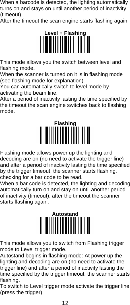
Chamk lnorated 089260831578 IG300BT C1/C2 Area image Barcode Scanner User Manual
Champtek lncorporated IG300BT C1/C2 Area image Barcode Scanner
UserManual.wiki
>
Chamk lnorated
>
089260831578 User Manual
user manual
Navigation menu
Upload a User Manual
Namespaces
Wiki Guide
HTML
PDF
Info
Views
User Manual
Discussion / Help
Navigation

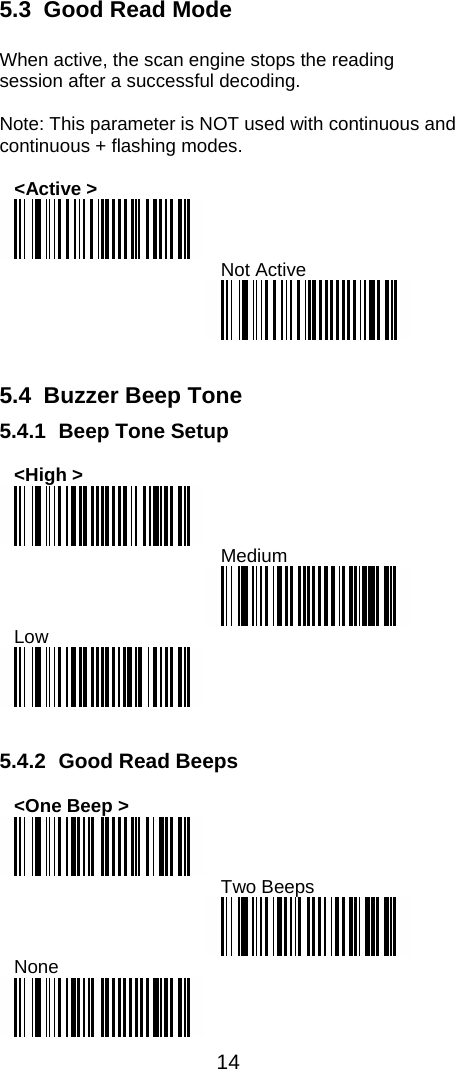
![41 7.14 Code 128 / GSI-128 Settings 7.16.1 Symbology Identifier <UDSI-Code 128-Default"B3"> <UDSI-GS1-128-Default"C9"> <Code Mark-Code 128-Default"D"> <Code Mark-GS1-128-Default"D"> 7.16.2 GS1-128 Identifier <Include ]C1 Identifier> Remove ]C1 Identifier 7.16.3 CIP 128 French Pharmaceutical Codes Active <Not Active > <FNC1 Separator Character (GS1-128 norms)-<GS>(1Dh)>](https://usermanual.wiki/Chamk-lnorated/089260831578/User-Guide-1280757-Page-46.png)

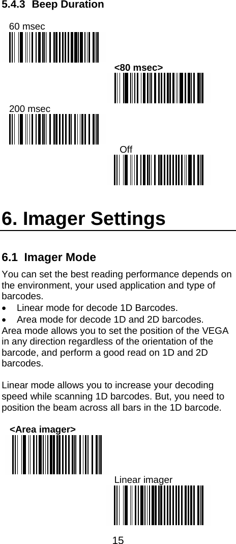
![61 7.36 Miscellaneous Parameters 7.38.1 Symbology Identifier Symbology Identifier Transmitted <Symbology Identifier Not Transmitted> With this function ON, a leading character will be added to the output string while scanning codes, user may refer to the following table to know what kind of barcode is scanned. Please refer to the table below for matching code Symbology Identifier of codes read in. ID Code Type IDAztec * Interleaved 2 of 5 ICodabar D GS1 DataBar Omini *Code 11 * GS1 DataBar Expanded *Code 39 * GS1 DataBar Limited *Code 93 D MSI code *Code 128 D Plessey Code DDataMatrix * PDF417 *EAN-8 FF MicroPDF417 *EAN-13 F UPC-A AEAN-128 D UPC-E E 7.37 Preambles and Postambles 7.39.1 Preamble The scanner can be programmed to output Barcode data according to the following format: [PREAMBLE STRING] [BAR CODE DATA] Example: To send a <STX> in front of the barcode, scan only programming code <STX>. As a result, the scanner will give the following barcode output: [<STX>] [BAR CODE DATA]](https://usermanual.wiki/Chamk-lnorated/089260831578/User-Guide-1280757-Page-66.png)
![62 <Preamble None > <STX> 7.39.2 Postamble The scanner can be programmed to output Barcode data according to the following format: [BAR CODE DATA] [POSTAMBLE STRING] Example: To send a <ETX> after the Barcode, scan only programming code <ETX>. As a result, the scanner will give the following barcode data output: [BAR CODE DATA] [<ETX>] Postamble None <CR+LF > CR LF <ETX>](https://usermanual.wiki/Chamk-lnorated/089260831578/User-Guide-1280757-Page-67.png)