Champion Industries Dl2000 Users Manual
2015-08-26
: Champion-Industries Champion-Industries-Dl2000-Users-Manual-802747 champion-industries-dl2000-users-manual-802747 champion-industries pdf
Open the PDF directly: View PDF ![]() .
.
Page Count: 27
- Model DL2000 Install Manual Rev1 02A_proof
- SPECIFICATIONS
- GETTING STARTED
- OPERATION
- WET SCRAPING
- HAND SCRAPING
- CLEAN SCREEN
- REMOVE SCREEN
- RE-INSTALL WASH ARM
- CLEAN WASH ARM
- REMOVE WASH ARM
- EMPTY SCRAP TRAY
- ADDENDUM FOR MACHINES INSTALLED IN THE CITY OF CHICAGO
- ELECTRICAL DIAGRAM
- Dl2000 Parts Manual Rev1.03A
Owner’s Manual
Keep with machine for reference
2674 N. Service Road, Jordan Station
Ontario, Canada LDR 1SO
905/562-4195 Fax: 905/562-4618
Toll-free:800/263-5798
Low Temp
3 Door Lift Models
Owner’s Manual
Revision 1.02A
3765 Champion Boulevard
Winston-Salem, NC 27105
336/661-1556 Fax: 336/661-1660 Toll-
free:800/858-4477

Title Installation & Operation Rev 1.02A
Page 2
TABLE OF CONTENTS
SPECIFICATIONS .................................................................................................................................. 3
3 Door Lift Model ................................................................................................................................................. 3
GETTING STARTED .............................................................................................................................. 4
Introduction to 3Door Lift Model .......................................................................................................................... 4
Receiving and Installation ..................................................................................................................................... 4
1. Packaging .................................................................................................................................................. 4
2. Plumbing.................................................................................................................................................... 4
3. Electrical .................................................................................................................................................... 4
4. Chemical Feeder ........................................................................................................................................ 4
5. Scrap Trap Accumulator ............................................................................................................................ 5
6. Water Line ................................................................................................................................................. 6
7. Activating Machine ................................................................................................................................... 6
OPERATION ............................................................................................................................................ 7
Starting Instructions ............................................................................................................................................... 7
Operating Instructions ........................................................................................................................................... 8
1. Scraping and Pre-rinse ............................................................................................................................... 8
2. Sorting and Racking .................................................................................................................................. 8
3. Racking dishes ........................................................................................................................................... 8
4. Racking glasses ......................................................................................................................................... 9
5. Racking flatware ........................................................................................................................................ 9
6. Stacking & Storage .................................................................................................................................... 9
Cleaning and Maintenance .................................................................................................................................. 11
1. Cleaning the drain screen......................................................................................................................... 11
2. Cleaning the washer arms ........................................................................................................................ 11
3. Check Operations .................................................................................................................................... 11
4. Cleanup .................................................................................................................................................... 12
5. Empty the Scrap Tray .............................................................................................................................. 12
Quick service guide ............................................................................................................................................. 13
Troubleshooting the 3 Door LiftModel ............................................................................................................... 14
Will Not Start .......................................................................................................................................... 14
Out of Chemical....................................................................................................................................... 14
Dishes/Glasses are Not Clean .................................................................................................................. 14
Machine Will Not Hold Water ................................................................................................................ 14
Water Running on the Floor .................................................................................................................... 14
Water Will Not Drain From the Machine ................................................................................................ 14
Water Coming Out of the Door ............................................................................................................... 14
Machine Will Not Shut Off ..................................................................................................................... 14
Machine Will Not Fill .............................................................................................................................. 14
ADDENDUM FOR MACHINES INSTALLED IN THE CITY OF CHICAGO ................................ 15
ELECTRICAL DIAGRAM .................................................................................................................... 16
Title Installation & Operation Rev 1.02A
Page 3
SPECIFICATIONS
3 Door Lift Model
WATER CONSUMPTION
PER RACK
.93 GAL.
3.53 L
PER HOUR
37 GAL.
139 L
OPERATING CYCLE
WASH TIME-SEC
45
45
RINSE TIME-SEC
30
30
DWELL TIME-SEC
15
15
TOTAL CYCLE
90 Sec
90 Sec
OPERATING CAPACITY
RACKS PER HOUR
40
40
WASH TANK CAPACITY
1.7 GAL.
6.44 L
PUMP CAPACITY
35 GPM
132.5 LPM
WATER REQUIREMENTS
- Minimum
120°F
49°C
- Recommended
140°F
60°C
WATER INLET
½”
-
DRAIN CONNECTION
2”
-
CYCLE TEMPERATURES
WASH-°F (Minimum)
120°F
49°C
FRAME DIMENSIONS
DEPTH
25 ¾”
65.4 cm
WIDTH
25 ¾”
65.4 cm
TABLE HEIGHT
34”
86.0 cm
MAX CLEARANCE FOR DISHES
17”
43.0 cm
ELECTRICAL*
115 VAC
16 AMPS
WASH PUMP MOTOR 1 HP
13.4 AMPS
*Warning: Electrical and plumbing connections need to be made by a qualified
service person who will comply with all available Federal, State and Local Health,
Electrical, Plumbing and Safety codes.
SHIPPING WEIGHT
E (Approximate)
E-EXT (Approximate)
218#
260#
98.7 kg
117.8 kg
Title Installation & Operation Rev 1.02A
Page 4
GETTING STARTED
Introduction to 3Door Lift Model
Dishwashers have been used worldwide for many years. This manual has been written to help you, the operator,
in your job. Your job is one of the “most important” in this restaurant. Why? Your product, the dishes and
glasses, is the first thing the customer notices when he sits down.. Clean, sparkling dishes and silverware will set
the mood for the customer when he observes the table setting.
Receiving and Installation
The dishwasher is shipped from the factory bubble packed on a pallet. The guidelines are listed in a step-by-step
procedure for your reference.
1. Packaging
Unwrap the machine and check for the following component parts:
Scrap accumulator complete with lid and scrap tray. This is normally an integral part of the
machine
Tube stiffeners. Tube stiffeners must be used to prevent the feed tubes from curling inside the
chemical pail and sucking air. These are pre-installed to the chemical pump and attached to the
back of the dishmachine. The ends of the chemical tubing have been flared so that the tubing will
not pull out of the stiffener. Red is for detergent, white for sanitizer, and blue for rinse aid.
2. Plumbing
The machine needs the following:
2” pipe for the drain outlet
½” pipe for the incoming water
A flex hose or quick disconnect union. The water inlet is at the top left corner of the dishwasher
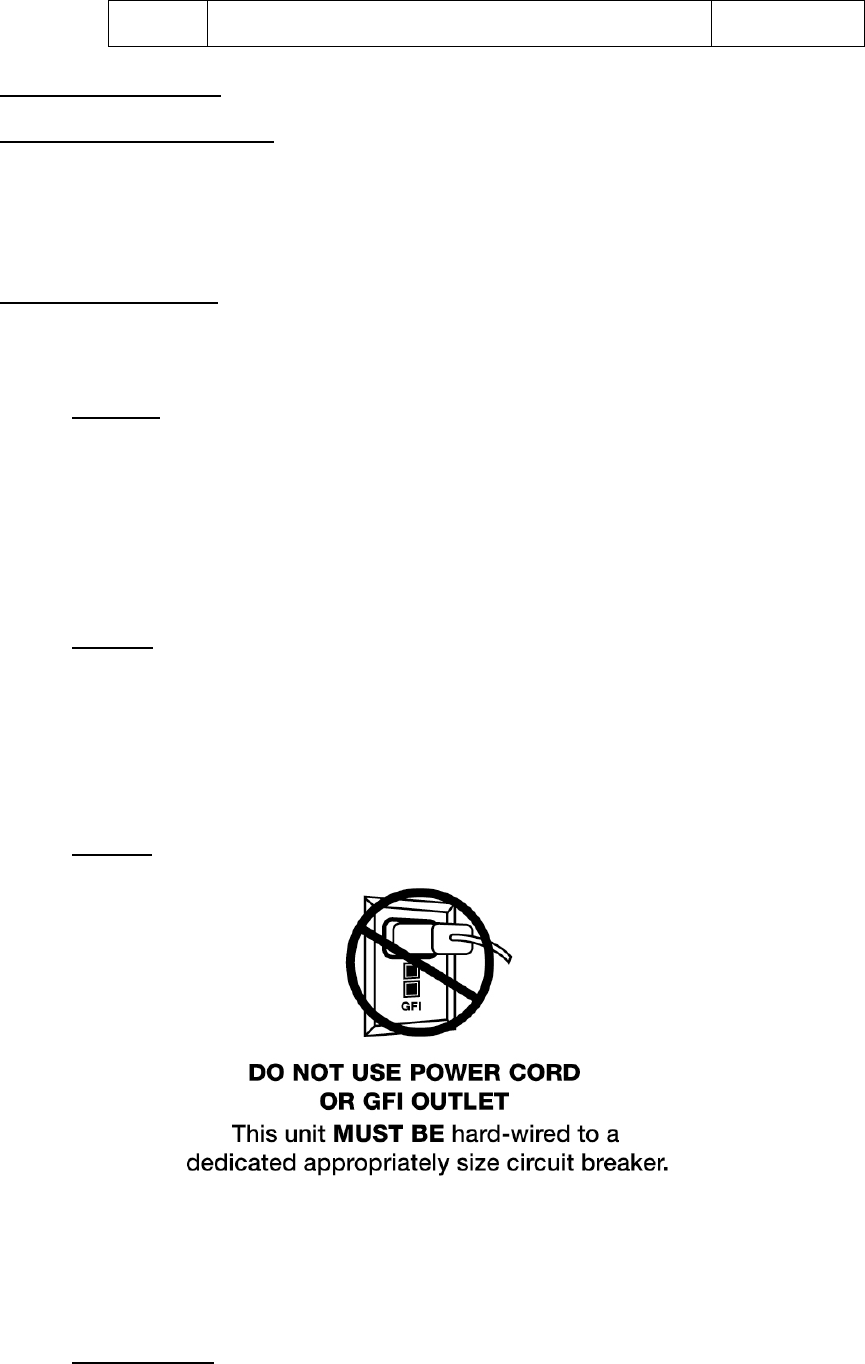
3. Electrical
The machine is 110 volt. The master switch is at the top left side of the control box.
WARNING: Electrical and plumbing connections need to be made by a qualified service person
who will comply with all available Federal, State, and local Health, Electrical, Plumbing Safety
Codes.
4. Chemical Feeder
The peristaltic pumps are assembled and included within the machine.
Title Installation & Operation Rev 1.02A
Page 5
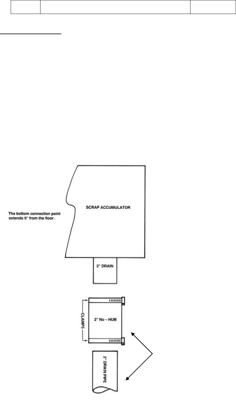
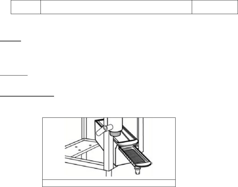
5. Scrap Trap Accumulator
The scrap trap accumulator is designed to perform two basic functions:
It allows a method to discharge all the heavy solids out of the machine with each wash and rinse
cycle.
It provides capacity to drain the contents of one cycle regardless of the ability of the existing drain
to accept the discharge rate.
There is a drain connection sleeve (2”) on the bottom of the scrap accumulator (See drain connection
instruction).
Standard dishwashers operate on 110 volts. Other voltage requirements are available on request. When
installing the single rack units, either model 3 Door Lift, it is recommended that a clean 20 amp circuit
be provided to the machine.
WARNING: Electrical and plumbing connections need to be made by a qualified service person who
will comply with all available Federal, State, and local Health, Electrical, Plumbing Safety Codes.
SCRAP TRAP ACCUMULATOR CONNECTION:
Not supplied with
Machine

Title Installation & Operation Rev 1.02A
Page 6
6. Water Line
The 3 Door Lift model should plumbed with ½” hot water line. The time necessary to deliver water to
the machine is controlled by the number four cam. This cam provides the serviceman with the
opportunity to fine-tune the machine to deliver the proper amount with each cycle. Refer to the service
manual for an in depth discussion of this procedure.
7. Activating Machine
The machine is equipped with a prime switch to activate the peristaltic pump at any time the master
switch is “ON”.
Following the completion of the installation, always fill the machine with water before the machine is
started.
Hold the fill button until the water level is approximately ½” to ¾” below the overflow hole in the
PVC standpipe. This water level should be approximately even with the bottom edge splash guard
in sump area of machine.
Activate the prime switches for the three chemical pumps until the product is discharging into the
sump.
To start the machine, close the doors and the machine will cycle automatically.
The amount of product delivered by each cam is controlled by changing the opening in each cam. When
the micro switch rides down into the cam, the peristaltic pump motor begins to rotate. It will continue to
rotate until it rides up out of the groove. Therefore, to extend the amount of product delivered to the
machine, open the groove. To reduce the amount of product delivered to the machine, close the groove.
Cams are slip fit. A cam adjustment wrench is provided, but the cam can be adjusted with a small
screwdriver or the edge of a table knife.
Technical personnel are available during normal business hours should you, as an installer, have any
questions. We are available to serve you at 800-854-6417.
DISCLAIMER OF LIABILITY OF WARRANTY: COMPANY EXPRESSLY DISCLAIMS ANY AND ALL WARRANTIES, EXPRESS OR IMPLIED, RELATING TO THE INSTALLATION OF ANY AND ALL
EQUIPMENT THAT IS INSTALLED BY CHEMICAL DEALERS, CONTRACTED SERVICERS OR THIRD PARTY SERVICERS TO EQUIPMENT. IF THE INSTALLATION INSTRUCTIONS ARE NOT
FOLLOWED EXACTLY (TO THE LETTER), OR, IF ANY PERSON OR COMPANY CONDUCTING THE INSTALLATION OF THE EQUIPMENT, REVISE THE INSTALLATION PROCEDURES OR ALTER
THE INSTRUCTIONS IN ANY MANNER, THE WARRANTY BECOMES VOID. IF, DUE TO THE IMPROPER INSTALLATION OF EQUIPMENT, THIS EQUIPMENT CEASES TO OPERATE PROPERLY OR
AFFECTS OTHER PARTS OF THE DISHWASHING EQUIPMENT, IN THAT THE OTHER PARTS BECOME DEFECTIVE, THE WARRANTY BECOMES VOID. A WILL NOT BE LIABLE OR RESPONSIBLE
OR WARRANT EQUIPMENT, DUE TO IMPROPER INSTALLATION OF ANY MODEL DISHWASHER.

Title Installation & Operation Rev 1.02A
Page 7
OPERATION
3 Door Lift dishwashers have been used worldwide for many years. This manual has been written to help you, the
operator, in your job.
The manual is divided into three sections. Sections A and B cover start-up and dish handling, and section C
covers troubleshooting.
Starting Instructions
Drain water if it is cold by lifting drain ball until all water is out of the machine.
Check drain screen and clean.
Replace it properly into the sump housing.
Check wash arm spray tips. If clogged, clean with toothpick and rinse at sink.
Check chemical lines to chemical containers
A. Red – detergent line
B. Blue – rinse agent line
C. Clear/White – sanitizer destainer line.
Press fill switch; fill until water is ½” lower than overflow on drain ball shaft or to the bottom of splash
shield.
Hold fill switch in until water level is proper and check temperature (should be approximately 140
degrees Fahrenheit; 60 degrees Celsius).
Insert tray of dishes into machine and close doors. Machine will automatically start when doors are
closed.
After the machine green cycle light turns off, raise doors, remove trays, and allow to dry before stacking.
If the doors are lifted during a wash cycle, the machine will automatically shut off.
3 Door Lift Model will complete the wash and rinse cycle and automatically feed the proper chemical
and turn itself off.
Title Installation & Operation Rev 1.02A
Page 8
Operating Instructions
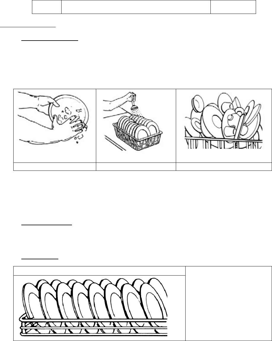
1. Scraping and Pre-rinse
Remove remaining food from utensils. Scrape by hand or by using a cleaning tool such as a sponge or
rubber spatula. For protection of the hands, wear gloves.
Use a pre-rinse hose for wet scraping to remove small particles of soil not removed by the hand scraping
operation. The purpose is to keep excessive garbage from going into the dishwashing machine.
HAND SCRAPING
WET SCRAPING
DON’T PILE DISHES!!
For flatware, it is recommended that they be pre-soaked in a deep pan, generally a bus pan, using a
presoak detergent. This will prevent drying or adhering of soil on flatware and reduce tarnishing. A
presoak detergent is especially useful for the removal of protein soil such as egg, syrup, etc. Allot
approximately 30 minutes for presoaking if possible for better results.
2. Sorting and Racking
Properly placing the utensils in the rack is one of the most important jobs the operator must perform.
Sort out different utensils, separating dishes, bowls, cups, glassware and flatware.
3. Racking dishes
PROPER RACKING
Note in the illustration that the
plates are racked without
overlapping and that the sprays
from the top spray arm will strike
the food contact surfaces of the
dishes (face of the dishes)
Rack all the same sized plates together row by row. The dish rack will hold them just right for proper
washing. The entire surface of the soiled dish must be covered by the spray arm to provide sufficient
scrubbing action when the detergent solution is being sprayed on that dish.
Stacking dishes will not save time because the dishes will not be cleaned during the wash cycle and will
require sorting and rewashing.
Title Installation & Operation Rev 1.02A
Page 9
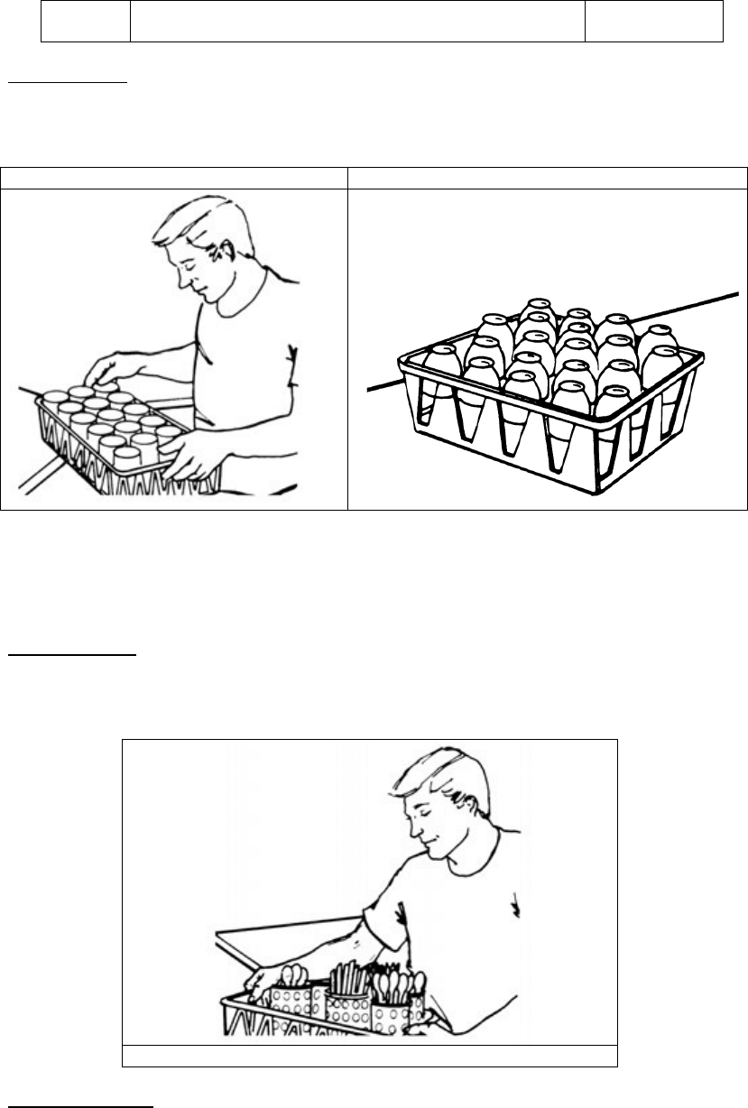
4. Racking glasses
Glasses, cups, bowls and other deep dishes must be racked faced down. This is so as not to carry out
wash water and so the sprays can work on the internal surfaces. Rack glasses and cups in a properly
sized compartmentalized glass rack. Allow to air dry.
GLASS RACKING
CUP RACKING
Glasses should be placed in the racks upside down in each compartment. The rinse additive is injected
into the rinse water to prevent spotting and speed the drying process. (Note: Company’s representative
can help you select the proper glass rack for your glasses.
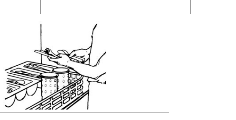
5. Racking flatware
After presoaking, flatware is placed in a wash basket with handles down to prevent them from “nesting”
which provides maximum exposure to the wash process.
WASH BASKET
6. Stacking & Storage
Title Installation & Operation Rev 1.02A
Page 10
SORTING AND STORING FLATWARE
Stacking and storage of dishes being washed and sanitized is very important. A dish may be perfectly
washed but be completely contaminated from the handling after washing. Avoid storing dishes where
they may be soiled. Handling dishes with the hand on the food contact surfaces should be reduced to a
minimum (towel drying is an incorrect procedure). Do not stack plates and dishes higher than 12 inches.
Their combined weight can destroy the porcelain surface on the bottom plates.
Title Installation & Operation Rev 1.02A
Page 11
Cleaning and Maintenance
Certain times of the day should be allotted to cleaning dishwashing machine. Follow the cleaning and inspection
procedures listed below:
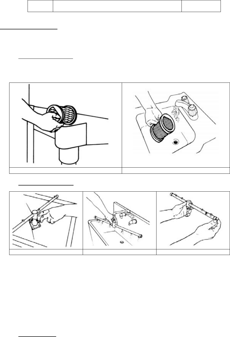
1. Cleaning the drain screen
Remove the drain screen and thoroughly clean all foreign material from screen as shown in the illustration.
DO NOT BANG THE SCREEN ON THE TABLE TO JAR FOOD LOOSE. Use the faucet or the pre-rinse
hose. Re-install drain screen and ensure that it is in the proper position.
REMOVE SCREEN
CLEAN SCREEN
2. Cleaning the washer arms
REMOVE WASH ARM
CLEAN WASH ARM
RE-INSTALL WASH ARM
Inspect the upper and lower spray arms to ensure they are not clogged with food scraps. Otherwise, full
and uniform spray pressures will not be delivered to the soiled dishes.
If there is any question as to the spray arms being clear of food scraps, the spray arms should be
removed and cleaned. Note that water will blow from all jets if they are open. Use toothpick to open
clogged jets and flush to ensure that food scraps are out of the arm. If necessary, the stainless plug in the
end of the arm can be unscrewed and removed to clean the inside of the arm tube at the sink.
After the arm has been thoroughly cleaned, re-install back into the base.
3. Check Operations
Operate the machine for one cycle. Watch detergent, sanitizer and rinse additive “delivery tubes” at the
point where they inject chemical into the machine. Remember: red tube – detergent; blue tube-rinse; and
clear white tube-sanitizer. Check temperature at the end of the cycle for 120
°
F minimum.
Title Installation & Operation Rev 1.02A
Page 12
4. Cleanup
Wipe down the machine and check the chemical level in the containers. Also inspect machine
for leaks or other items that might cause trouble during a rush period. You are now ready to wash
dishes.
Remember: The chemical containers should be saved for pickup by the serviceman during his regular
call. Do not throw them in the trash bin.
5. Empty the Scrap Tray
Remove scrap tray drawer and thoroughly rinse out. Clean tray after each meal, or once every hour if
very busy.
EMPTY SCRAP TRAY

Title Installation & Operation Rev 1.02A
Page 13
Quick service guide
TECHNICAL ISSUE
CAUSE
SOLUTION
Starts with doors open Faulty #1 micro switch (start/stop) Replace micro switch
Faulty door switch Replace switch
Faulty #1 micro switch (start/stop) Replace micro switch
Continues cycle Faulty start/fill switch Replace switch
Faulty door switch Replace door switch
Wash motor will not shut off Delimer switch in wrong position Switch to
NORMAL
position
Faulty motor contactor Replace contactor
Faulty # 6 micro switch Replace micro switch
Sanitizer pump does not run Delimer switch in wrong position Switch to
NORMAL
position
Faulty sanitizer pump motor Replace sani motor
Debris inside water solenoid valve Clean and replace diaphragm
Water solenoid leaking High water pressure on supply line Decrease water pressure
Faulty water solenoid valve Replace valve
Leaking drain ball Replace drain ball
Does not fill or hold water in tank
Faulty #4 micro switch (Fill) Replace micro switch
Debris inside water solenoid valve or
Faulty valve
Clean and replace diaphragm/valve
Worn internal vac. Brkr parts
Replace or clean parts
Vacuum breaker leaks Faulty check valve Replace check valve
Low incoming water pressure Increase water pressure
Only runs when start/fill switch is
depressed Faulty #1 micro switch (start/stop) Replace micro switch
Faulty Door switch Replace door switch
Will not start/ nothing works Wall breaker tripped Reset breaker
Master on/off switch on machine turned
off, or faulty
Reset or replace master switch
Faulty #2 Micro switch (cycle reset) Replace micro switch
Runs, but none of the other functions
engage Faulty ice cube relay (yellow relay) Replace relay
Faulty motor contactor Replace contactor

Title Installation & Operation Rev 1.02A
Page 14
Troubleshooting the 3 Door LiftModel
Will Not Start
1. Check master switch on the control box to make sure that it is “ON”.
2. Check circuit breaker that services the dishwasher. Make sure it is “ON”.
3. After (ONLY after) checking steps 1 and 2, call the service technicians.
Out of Chemical
Check backup supply of chemicals. REMEMBER! Red product label to red tube, blue product label to blue
tube, and clear/white product label to clear/white tube. Note that sometimes extra product is left in storage
area at the direction of the restaurant manager. Before calling service technicians, check with the manager
for backup supplies.
Dishes/Glasses are Not Clean
1. Before you call service technician, check your temperature gauge on the machine. Check to insure water
temperature is at least 120
°
F. The 3Door dishwasher must have hot water delivered from the primary
heater at 120
°
to 140
°
F. If temperature is okay, then…
2. Check that your water softener contains salt and is operating properly. Your service agreement from
company calls for hot/soft water.
3. Check that dishes are racked properly. Check the screen and wash arm tips. If they are clear, call the
service technicians.
Machine Will Not Hold Water
Check the drain actuator for a knife, spoon, fork or foreign material then remove.
Water Running on the Floor
If water is overflowing, the scrap accumulator or the scrap drawer may need to be cleaned. If not, call your
plumber- the drain may be clogged.
Water Will Not Drain From the Machine
Check the drain solenoid. Call the service technician.
Water Coming Out of the Door
End plugs may be missing or lose. Check inside the scrap accumulator drawer. If the end plug came off
during operation, it will be inside the scrap trap tray. Simply replace. If end plug is lost, call your service
technician.
Machine Will Not Shut Off
You can turn off the machine in an emergency by turning off the master switch located on the back of the
control box. After turning off the master switch, call service technician.
Machine Will Not Fill
Check gate valve on the top of the machine. Make sure “handle” has been opened. If it is, call your service
technician.

Title Installation & Operation Rev 1.02A
Page 15
ADDENDUM FOR MACHINES INSTALLED IN THE CITY OF CHICAGO
All food dispensing establishments using chlorine or other approved chemical sanitizers shall at all times
maintain an adequate testing device.
Dishes and other eating and drinking utensils to be washed in a dishwashing machine shall be properly scraped
and pre-rinsed and shall be stacked in racks or trays so as to avoid overcrowding and so as to permit wash and
rinse waters to rinse waters to reach all surfaces of each utensil.
In machine washing, multi-use eating and drinking utensils shall be washed in water containing suitable
detergent at a temperature from 120 degrees F. to 140 degrees F. or other method approved by the Department of
Health.
The water in the wash tank shall be changed during operation as often as necessary to keep it reasonably clean.
An effective concentration of detergent in the wash water shall be maintained at all times.
Bactericidal treatment shall consist of exposure of all surfaces of dishes and utensils being washed to a rinse of
clean water, at a temperature of not less than 180 degrees F. or other method approved by the Department of
Health.
All dishwashing machines shall maintain a flow pressure not less than 15 or more than 25 pounds per square inch
on the fresh water line at the machine and not less than 10 pounds per square inch at the rinse nozzles. A suitable
gauge cock shall be provided immediately upstream from the final rinse sprays to permit checking the flow of the
final rinse water. An easily readable thermometer accurate to
±
2 degrees F. shall be provided on both the wash
and rinse water lines of the dishwashing machine which will indicate the temperature of the water solution
therein.
Dishwashing machines shall be thoroughly cleaned at least once each day. The pumps and the wash and rinse
sprays or jets shall be so designed that a forceful stream of water will reach all surfaces of the utensils when they
are properly racked. These parts shall be thoroughly cleaned at least once each day. The pumps and the wash and
rinse sprays or jet shall be so designed that a forceful stream of water will reach all surfaces of the utensils when
they are properly racked. These parts shall be readily accessible for inspection and cleaning.
After bactericidal treatment, utensils and containers shall be stored at a sufficient height above the floor in a
clean, dry place protected from flies, splash, dust, overhead leakage and condensation, and other contamination
until used for serving.
Drain racks, trays and shelves shall be made of non-corrodible material and shall be kept clean.
In handling containers and utensils the surface thereof which come in contact with food or drink shall not be
touched by hands, except during the process of washing.
Tables for clean and dirty dishes and food shall be so arranged that the dirty dishes will be as far removed from
the food and clean dishes as may be possible.
All single-service articles and utensils shall be purchased in sanitary cartons and stored therein in a clean, dry
place until used, and after removal from the cartons, these articles shall be handled in such a manner to prevent
contamination.
Please note the following procedures must be followed for City of Chicago Approval:
1. All low energy models must have low-level sani alarms, both visual and audio.
2. All models must have a City of Chicago approval data label affixed to the machine.
3. Chlorine sanitizer must be a minimum of 100 PPM.
Title Installation & Operation Rev 1.02A
Page 16
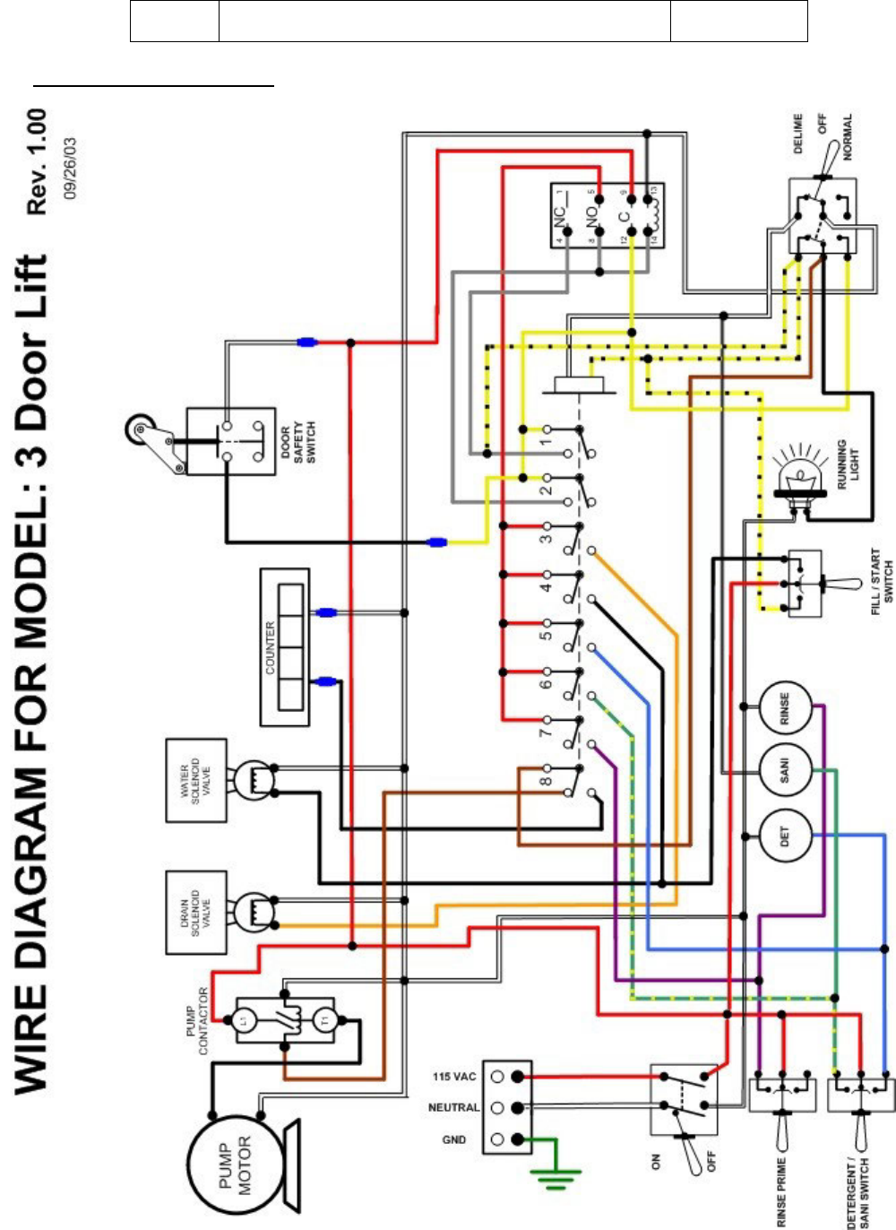
ELECTRICAL DIAGRAM
2674 N. Service Road, Jordan Station
Ontario, Canada LDR 1S 0
905/562-4195 Fax: 905/562-4618
Toll-free:800/263-5798
Low Temp
3 Door Lift Models
Parts Manual
Revision 1.03A
3765 Champion Boulevard
Winston-Salem, NC 27105
336/661-1556 Fax: 336/661-1660 Toll-
free:800/858-4477

Title Parts Manual Rev 1.03A
Page 2
TABLE OF CONTENTS
PARTS MANUAL .................................................................................................................................... 3
Initial Parts Kit (Part # 01100.85).......................................................................................................................... 3
Exploded View Drawings ...................................................................................................................................... 4
Cabinet Assembly .............................................................................................................................................. 4
Control Box ....................................................................................................................................................... 5
Plumbing System ............................................................................................................................................... 6
Pump Assembly ................................................................................................................................................. 7
Spray System Assembly .................................................................................................................................... 8
Drain System Assembly .................................................................................................................................... 9
Door Actuator Assembly ................................................................................................................................. 10
Peristaltic Pump Assembly .............................................................................................................................. 11

Title Parts Manual Rev 1.03A
Page 3
PARTS MANUAL
Initial Parts Kit (Part # 01100.85)
PART NO.
D E S C R I P T I O N
QTY
00100.00
Drain Ball Solenoid 120V
1
00115.08
Drain Sump Screen (A/C)
1
00120.02
Thermometer (Bi Metal)
1
00121.25
Drain Ball
1
00200.10
Pump Assy. 110/220V 60Hz (Open)
1
00206.30
Pump Seal Kit
1
00307.30
Spray Arm Assy. ES Long w/bearing &plug
1
00404.82
Motor Contactor 115V/60HZ
1
00411.00
Micro Switch
1
00415.00
Peristaltic Pump Assy. 120V/60hz
1
00418.00
Peristaltic Pump Cover
1
00425.51
Chemical Tubing Blue
50
00425.53
Chemical Tubing Red
50
00425.54
Chemical Tubing White
50
00433.10
Master Switch (20 Amp)
1
00435.10
Squeeze Tube Orange 8"
1
00500.00
Timer Motor 90 Sec 110V/60Hz
1
00562.00
Roller Door Switch
1
00602.00
Door Spring
1
00631.00
Ice Cube Relay 120V
1
00955.00
5/16-18 X 5/8 Thumbscrew
1
01550.00
Solenoid Stop
1
03470.01
Toggle Switch(Moment) .25 Flat Term
1
Title Parts Manual Rev 1.03A
Page 4
Exploded View Drawings
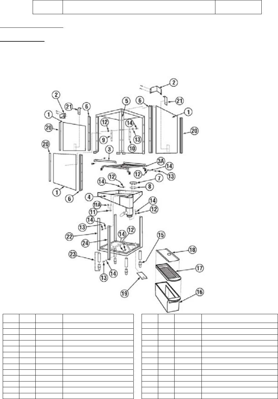
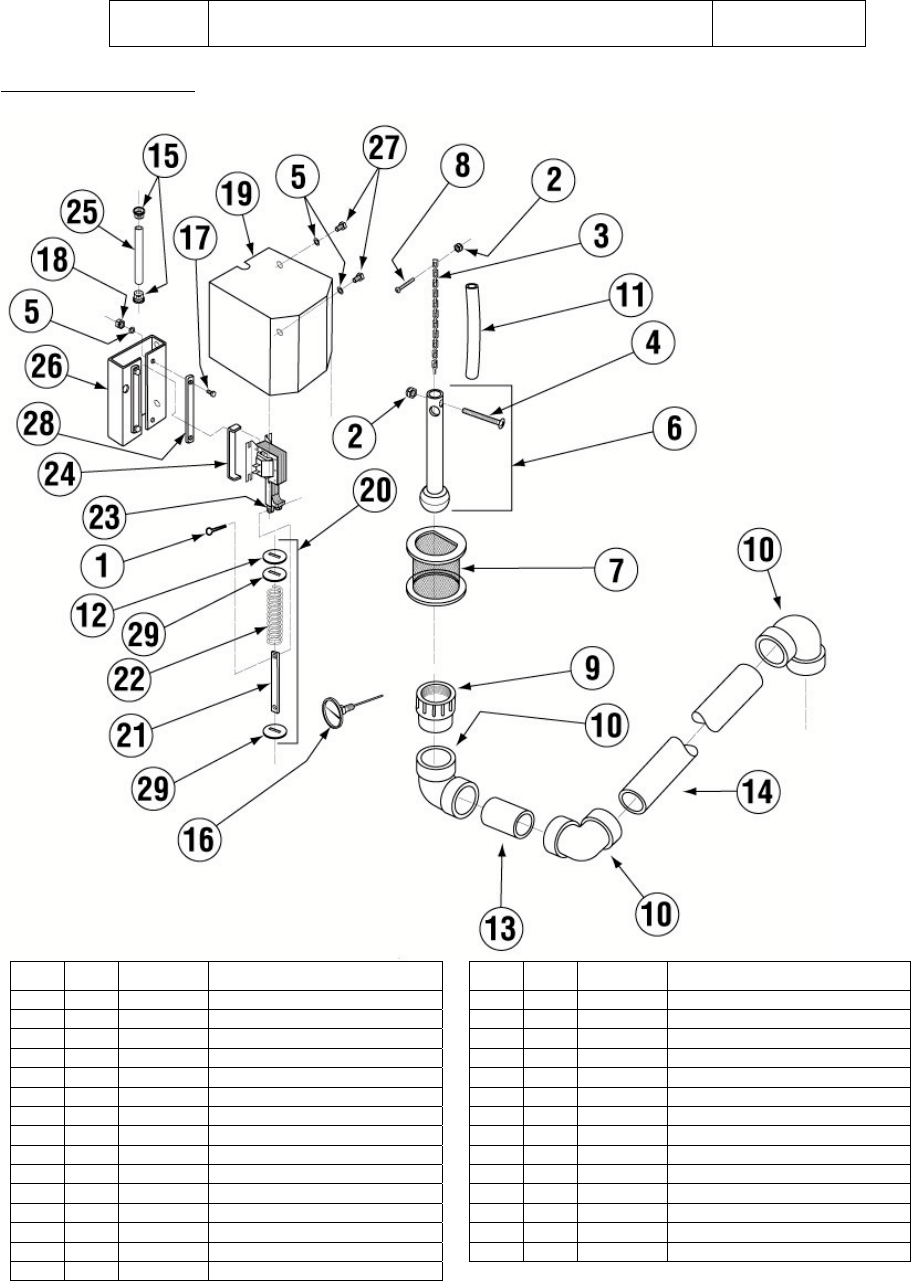
Cabinet Assembly
Item Qty Part No Description
Item Qty Part No Description
01
3
01506.45
Door Standard (Blanks)
12
31
00912.00
1/4-20 Nylon Lock Nut
02
2
01516.50
3-Door Bracket outside Style
13
4
00906.00
1/4-20 X 1/2 Hexhead Bolt
03
1
01505.16
Corner Tray Track Bolt On Rail
14
9
00924.00
1/4 SS Washer
03a
1
01505.10
Tray Track
15
4
01310.20
Bullet Foot Plastic
04
1
01502.70
Pan - Bolt On No Legs
16
1
01577.10
Molded Scrap Trap Body - New
05
1
01510.40
Wrapper
17
1
01577.21
S/S Scrap Trap Drawer
06
6
01554.30
EZ Glide Door Guide SS 21 1/8"
18
1
01577.30
Molded Scrap Trap Lid - SS
07
1
00124.65
Drain Ball Seat
19
1
01577.50
Molded Scrap Trap-Mount Bracket
08
1
00125.10
Drain Sump Gasket
20
6
00636.10
EZ Glide Door Guide Sq 21 7/8”
09
1
00101.20
Solenoid Bracket C LH
21
2
17552.00
Door Stop
10
1
00101.10
Solenoid Bracket C RH
22
1
01502.75
E Stand - Bolt On No Legs
11
1
01558.20
Chem. Support Bracket
23
4
01145.00
Leg Assy. w\Adjustable Socket
11a
3
00427.00
Snap Bushing 375-4
24
1
01570.24
Pan Support Bracket - C long
Title Parts Manual Rev 1.03A
Page 5
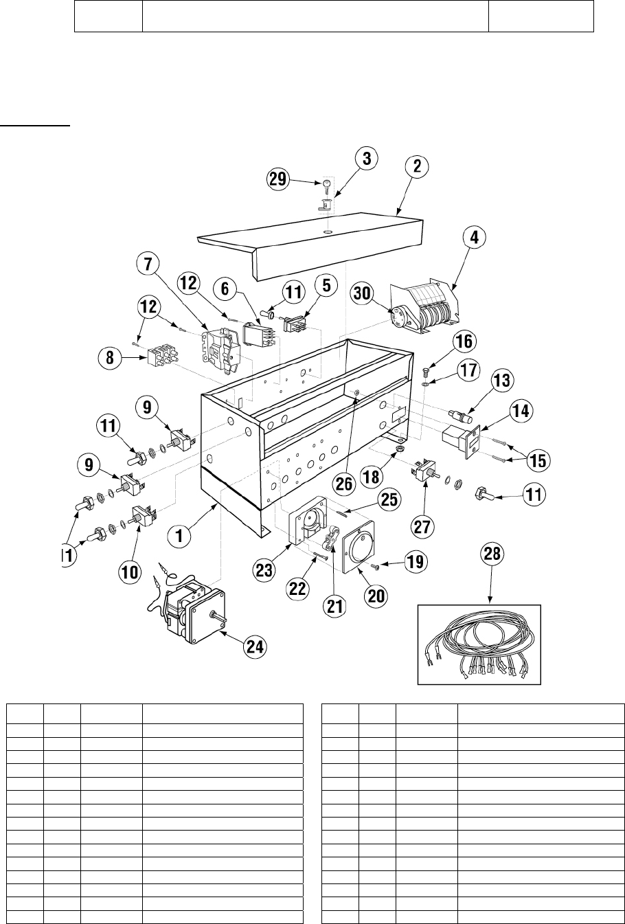
Control Box
Item Qty Part No Description
Item Qty Part No Description
1
1
01503.09
Control Box Body
16
4
00906.00
1/4-20 X 1/2 Hexhead Bolt
2
1
01504.09
Control Box Lid
17
4
00924.00
1/4 SS Washer
3 1 00449.00 Lock And Key 18 4 00912.00 1/4-20 Nylon Lock Nut
4*
1
00407.80
Timer 90 Sec 8 Cam 120/60Hz
19
12
00911.00
8-32 X 1/2 Panhead Screw
5
1
00475.00
Toggle Sw dpdt 5 amp/Delimer
20
3
00418.00
Peristaltic Pump Cover
6
1
00631.00
Ice Cube Relay 120V
21
3
00419.00
Peristaltic Pump Rotor Assy
7
1
00404.82
Motor Contactor 115V/60HZ
22
6
00919.00
10-32 X 1 1/2 Panhead Bolt
8
1
00454.10
3 Pole Socket Terminal Block
23
3
00417.00
Peristaltic Pump Block
9
2
03470.00
Toggle Sw Momentary ScTerm
24
3
00416.00
Peristaltic Pump Motor 120/60
10 1 00471.10 Toggle switch DPST 20AMP 25 3 00918.00 10-32 X 1 1/2 Filister Bolt
11
5
00470.10
Toggle Switch Rubber Boot
26
4
00917.00
8-32 PM Nut
12
4
00911.50
8-32 X 3/8 Pan Head Screw
27
1
03470.01
Toggle Sw Moment 25 Flat Term
13 1 00406.00 Control Box Light .5" Dia Red 28 1 00414.86 Wiring Harness
14
1
03408.50
Counter (Panel Mount) 120/60
29
1
00450.00
Key Only
15
2
00907.00
6-32 X 1/2 SS Panhead Screw
30
1
00500.00
Timer Motor 90 Sec 115V/60Hz
*00411.00 –Microswitch only.
Title Parts Manual Rev 1.03A
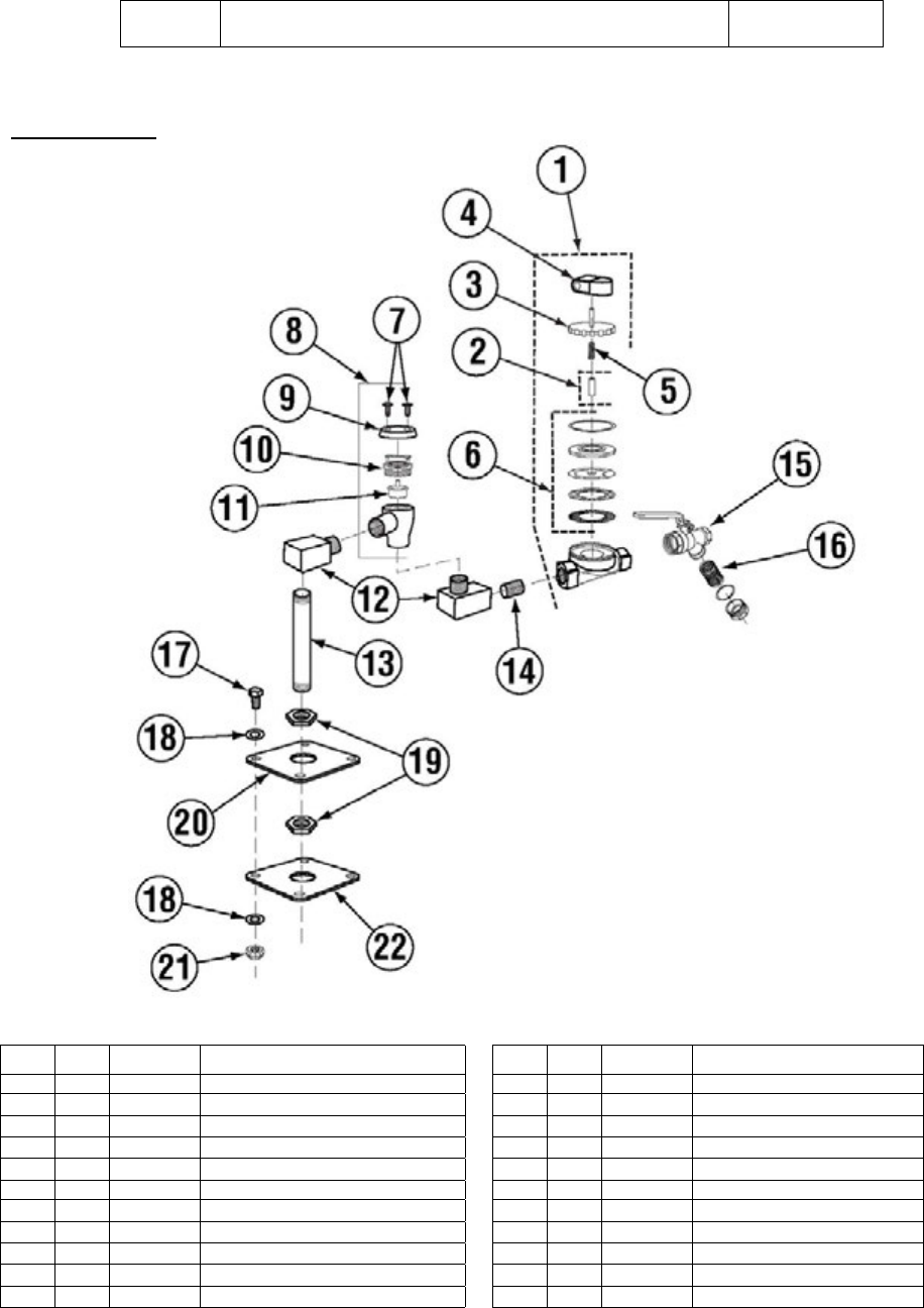
Page 6
Plumbing System
Item Qty Part No Description Item Qty Part No Description
01
1
03603.10
½” Water Sol Valve 120v/60hz
12
2
00745.00
½” 90 Deg Street Elbow
02 1 00786.00 Water Sol Plunger G JE ¾ & ½ 13
1
00747.10
Nipple Brass ½” x5
03
1
03603.20
½ “Water Solenoid Bonnet
14
1 00742.00 ½”x1-1/2” Brass Nipple
04 1 00738.10 Solenoid Coil JE 120V (¾ & ½) 15 1 41062.00 ½” Strainer Ball Valve
05 1 00706.10 ¾” Solenoid JE Spring Only 16
1
41062.10
½” Ball Valve Strainer Only
06
1
00707.00
1/2" Water Solenoid Repair Kit JE
17
4
00914.10
1/4-20 X 5/8 Hexhead Bolt
07
2 00421.51 6-32 x 1/4" Pan Head Screw
18
8
00924.00
1/4 SS Washer
08
1
03624.00
Vacuum Breaker Assembly, Watts**
19 2 00721.00 ½” Jamb Nut
09
1
00739.50
Vacuum Breaker Cap, SS (fits ½/ ¾)
20 1 13302.17 Flange Sq (3/4 Dia.)
10
1 03624.25 ½” Vacuum Breaker Bonnet, Brass
21
4
00912.00
¼-20 Nylon Lock Nut
11 1 03623.00 ½” Vacuum Breaker Repair Kit 22 1 04306.00 Square Manifold Gasket
Title Parts Manual Rev 1.03A
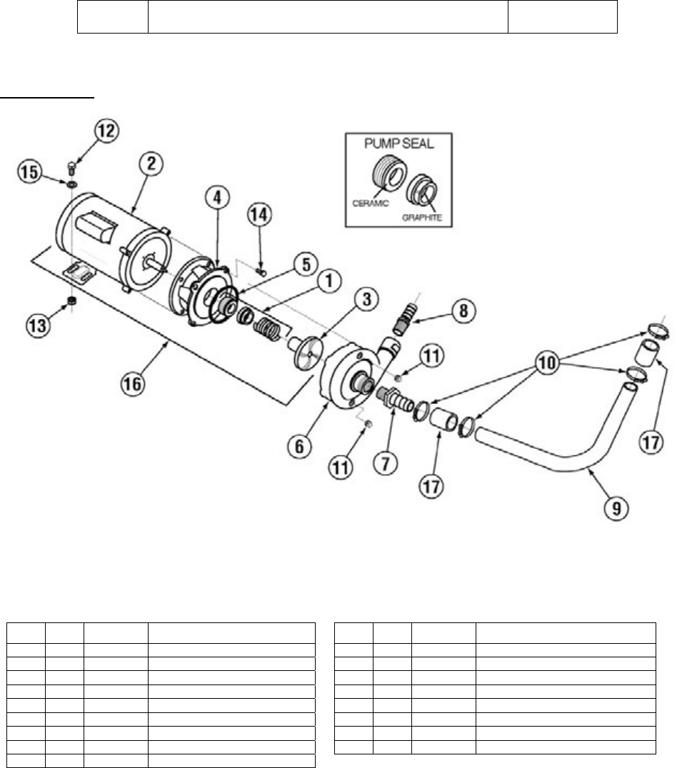
Page 7
Pump Assembly
Item Qty Part No Description Item Qty Part No Description
01
1
00206.30
Pump Seal Kit
10
2
03101.00
Hose Clamp # 16 1"
02
1
00201.00
Pump Motor 1Hp 115/208-230V
11
2
00238.00
3/8 Male Plug
03
1
03222.10
Impeller (Universal) Open
12
1
00906.00
1/4-20 X 1/2 Hexhead Bolt
04
1
03224.00
Pump Base
13
1
00912.00
1/4-20 Nylon Lock Nut
05
1
03226.00
Pump O Ring Gasket
14
4
00921.00
3/8-16 X 3/4 SS Hexhead Bolt
06
1
04206.00
Pump Cover
15
1
00924.00
1/4 SS Washer
07
1
50302.40
1 ¼ MIP X 1" Barb Fitting
16
1
00200.10
Pump Assy. 110/ 220V 60Hz
08
1
50302.06
1" MPT X 1" Barb PVC Sch 80
17
2
03108.67
Transfer Hose 1" Reinforced 2"
09 1 00246.40 Motor Suction Tube
Title Parts Manual Rev 1.03A
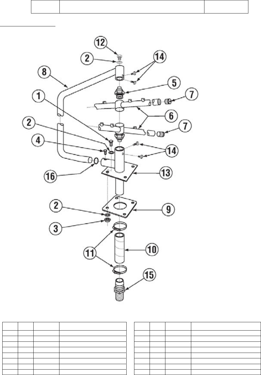
Page 8
Spray System Assembly
Item Qty Part No Description Item Qty Part No Description
01
4
00914.00
1/4-20 X 3/4 Hexhead Bolt
09
1
04306.00
Square Manifold Gasket
02
9
00924.00
1/4 SS Washer
10
1
03108.10
Transfer Hose 10"
03
4
00912.00
1/4-20 Nylon Lock Nut
11
2
03101.00
Hose Clamp # 16 1"
04
1
00966.10
10-32 X 1/4 Hexhead SS Bolt
12
1
00905.82
1/4-20 X 3/8 Truss Head Bolt
05
2
00342.00
Spray Arm Bearing
13
1
00357.10
Lower Spray Base EAH
06
2
00310.00
Spray Arm
14
4
00955.00
5/16 -18x 5/8 Thumbscrew
07
4
00308.50
Spray Arm End Plug SS
15
1
50302.06
1" MPT X 1" Barb PVC Sch 80
08
1
00305.03
Spray Manifold
16
1
00302.84
Spray Base O ring
Title Parts Manual Rev 1.03A
Page 9
Drain System Assembly
Item Qty Part No Description Item Qty Part No Description
01
1
00900.10
Cotter pin 1/8" X 1"
16
1
00120.02
Thermometer (Bi Metal)
02
2
00927.00
8-32 Nylon Lock Nut
17
4
00914.00
1/4-20 X 3/4 Hexhead Bolt
03
1
00110.07
Drain Ball Chain-12 Link
18
4
00915.00
1/4-20 SS Nut
04
1
00902.00
8-32 X 1 1/4 Panhead Bolt
19
1
01507.50
Solenoid Cover TM A/B/C
05
6
00922.00
1/4 Lock Star Washer
20
1
00122.00
Drain Solenoid Spring Assy.
06
1
00121.25
Drain Ball Assy
21
1
01551.00
Solenoid Link
07 1 00115.08 Drain Sump Screen 22 1 00105.00 Solenoid Spring
08
1
03812.00
8-32 X 5/8 Panhead Screw
23
1
00100.00
Drain Ball Solenoid 120V
09
1
01313.20
2" Spg X Fip Adapter
24
1
01550.00
Solenoid Stop
10 3 01312.20 2" Vent ELL Hub X Hub 25 1 00464.07 3/8 SS Tubing(TM A/B Sol Wire)
11
1
41019.11
1/2 ID X 11/16 OD Hose 9"L
26
1
00102.00
Solenoid Base
12
1
00105.20
Drain Solenoid Linkage Washer
27
9
00906.00
1/4-20 X 1/2 Hexhead Bolt
13
1
05030.22
Tubing 2" X 3 3/4"
28
2
00103.00
Solenoid Bar
14
1
05030.24
Tubing 2" X 13 ¾"
29
2
00106.00
Slot Washer Large-SS
15
2
00936.00
312-250 Shorty Bushing
Title Parts Manual Rev 1.03A
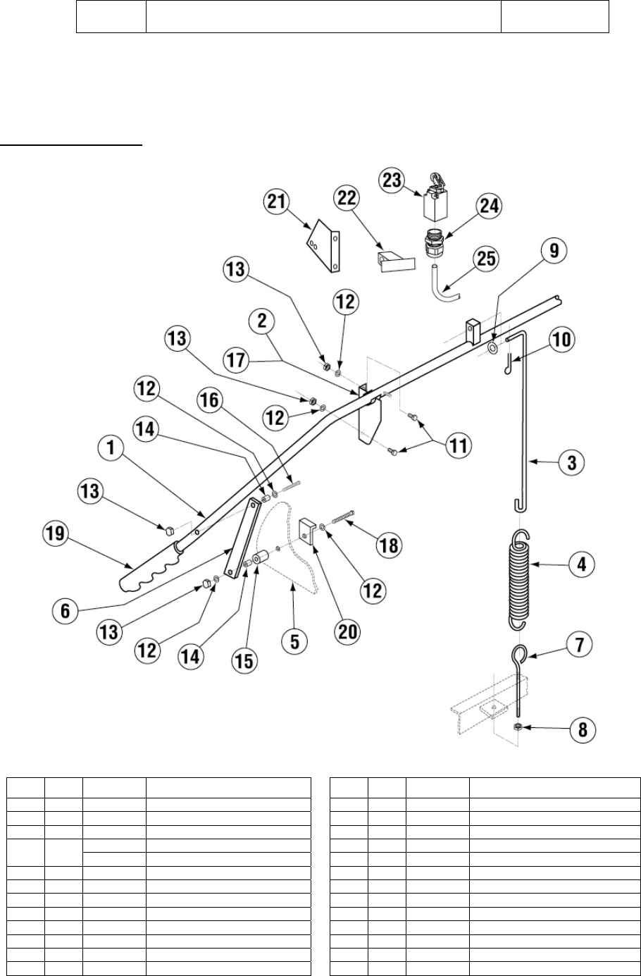
Page 10
Door Actuator Assembly
Item Qty Part No Description Item Qty Part No Description
01
1
00613.09
Door Handle EAH
13
8
00912.00
1/4-20 Nylon Lock Nut
02
1
01556.50
RH Door Handle Support Brckt
14
4
00610.00
Door Handle Spacer Small
03
1
00603.07
Door Spring Extension Rod AB
15
4
00611.00
Door Handle Spacer (Lg)
04 1 00602.00 Door Spring 16 2 00910.00 1/4-20 X1 1/2 SS Hexhead Bolt
00602.20
Door Spring –Heavy Duty
17
1
01555.50
LH Door Handle Support Brckt
05
2
01506.30
Door A B C M CMA-44
18
2
00903.00
1/4-20 X 1 3/4 SS Hexhead Bolt
06
2
01553.00
Door Handle Link
19
2
00607.04
Door Handle Cap 1"
07
1
00606.00
Eye Bolt 5/16-18 X 8 1/2
20
2
01552.00
Door Stop
08
1
00913.00
5/16-18 SS Nut
21
1
00563.40
Door Switch Bracket (8-08)
09
1
00926.00
5/16 SS Washer
22
1
00563.42
Door Switch Actuator (8-08)
10
1
00900.00
Cotter Pin
23
1
00562.00
Roller Door Switch
11
4
00906.00
1/4-20 X 1/2 Hexhead Bolt
24
1
00562.60
Connector Door Roller Switch
12
6
00924.00
1/4 SS Washer
25
1
00546.00
18 AWG Switch Cord
Title Parts Manual Rev 1.03A
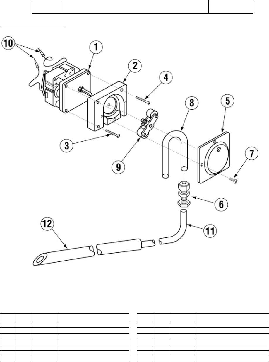
Page 11
Peristaltic Pump Assembly
Item Qty Part No Description Item Qty Part No Description
01
1
00416.00
Peristaltic Pump Motor 120v/60hz
08
1
00435.10
Squeeze Tube 8" Orange
02
1
00417.10
Peristaltic Pump Block
09
1
00419.00
Peristaltic Pump Rotor Assy.
03
2
00919.00
10-32 X 1 1/2 Panhead Bolt
10
2
00448.00
Male Barrel connector 14-16 gauge
04
1
00918.00
10-32 X 1 1/2 Filister Bolt
11
1
00425.51
Chemical Tubing Blue
05
1
00418.00
Peristaltic Pump Cover
11
1
00425.53
Chemical Tubing Red
06
1
03415.40
Liquid Tight Fitting 1/4"
11
1
00425.54
Chemical Tubing White
07
4
00911.00
8-32 X 1/2 Panhead Screw
12
1
00443.00
Tube Stiffener
