Champion Pumps Cpg Users Manual
2015-08-26
: Champion-Pumps Champion-Pumps-Cpg-Users-Manual-802857 champion-pumps-cpg-users-manual-802857 champion-pumps pdf
Open the PDF directly: View PDF ![]() .
.
Page Count: 11
Submersible Grinder Pump
CPG 2HP Grinder
Series
235651
Rev 11/12

Page 3
USER GUIDE
Congratulations on your purchase of a Champion Pump grinder pump system. With proper care and by following a
few simple guidelines, your grinder pump will give you many years of dependable service.
USE & CARE
The Champion grinder pump station is designed to handle routine, domestic sewage. Solid waste materials should
be thrown in the trash. While you station is capable of accepting and pumping a wide range of materials, regulatory
agencies advise that the following items should not be introduced into any sewer either directly or through a kitchen
waste disposal:
Glass; Metal; Diapers; Socks, rags or cloth; Plastic objects (e.g., toys, utensils, etc.) Sanitary napkins or tampons.
In addition you must never introduce into any sewer: Explosives; flammable material; lubricating oil and or grease;
strong chemicals; gasoline.
GENERAL INFORMATION
Your home wastewater disposal service is part of a low pressure sewer system. The key element in this system is
the grinder pump station. The basin collects all wastewater from the house. The solids in the sewage are then
ground to a small size suitable for pumping in the slurry. The grinder pump generates sufficient pressure to pump
this slurry from your home to the wastewater plant.
POWER FAILURE
This Pump cannot dispose of wastewater or provide an alarm signal without electrical power. If electrical power
service is interrupted, keep water usage to a minimum.
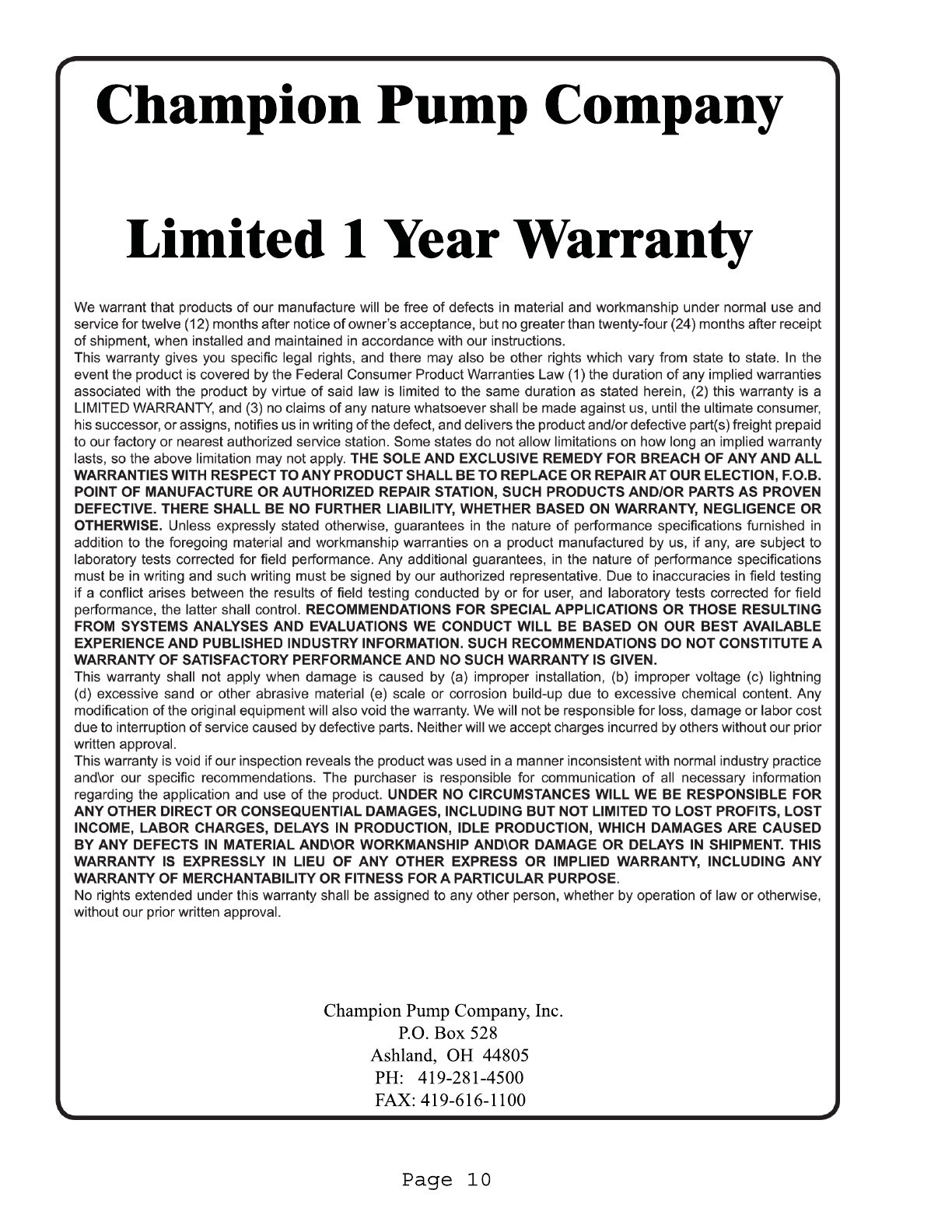
WARRANTY
Your pump is furnished with a warranty against defects in material or workmanship. A properly completed Start-
Up/Warranty Registration form must be on file at the Champion factory in order to activate your warranty. In
addition your pump must be installed in accordance with the installation instructions. If you have a claim under the
provisions of the warranty, contact your installer.
NOTE: ON CPG2022DSL MODELS, CAPACITOR KIT #28-0009-0000 MUST BE USED OR WARRANTY IS
VOID.
For future reference, record the following information:
Pump Model #____________________Pump Serial # ______________________
Installer_________________________Installer Phone #____________________
Date Installed____________________
RECEIVING / UNPACKING
Upon receiving the pump, it should be inspected for damage or shortages. If damage has occurred, file a claim
immediately with the company that delivered the pump. Unpack pump and record pump serial and model number
before installing. If the manual is removed from the packaging, do not lose or misplace.
SHORT TERM STORAGE
For best results, pumps can be retained in storage, as factory assembled, in a dry atmosphere with constant
temperatures for up to six (6) Months.
LONG TERM STORAGE
Any length of time exceeding six (6) months, but not more than twenty-four (24) months. The units should be
stored in a temperature controlled area, a roofed over walled enclosure that provides protection from the elements
(rain, snow, wind-blown dust, etc.), and whose temperature can be maintained between +40 deg. F and +120 deg.F.
If extended high humidity is expected to be a problem, all exposed parts should be inspected before storage and all
surfaces that have the paint scratched, damaged, or worn should be recoated with an air dry enamel paint. All
surfaces should then be sprayed with a rust-inhibiting oil. Pump should be stored in its original shipping container.
On initial start up, rotate shaft by hand to assure seal and motor rotate freely.

Page 4
USER GUIDE
INSTALLATION
The pump is provided with a leg kit in case a rail lift out system is not used. A minimum of 3” clearance must be maintained
between the pump and the basin bottom. If the feet are to be used, install the rubber threaded feet and lock with nut to ensure
3” clearance under pump for proper clearance of solids to enter pump inlet.
Assemble discharge piping or hose assembly to the pump. Discharge piping should be as short as possible. Both a check
valve and a shut off valve are required for each pump being used. The check valve is used to prevent backflow into the sump.
Excessive backflow can cause flooding and /or damage to the pump. The shut-off valve is used to stop system flow during
pump or check valve servicing. If pump is installed with a discharge hose rather than a moveable fitting assembly, make sure
the discharge pipe has a 1/8” hole approximately 5” from tend neatest volute and oriented towards the pump body.
ELECTRICAL CONNECTIONS
Breaker Recommendations: 25 AMP (208V-230V Single Phase) : 20AMP (208V-230V Three Phase) :15AMP (460V Three
Phase). The quick connect cord assembly mounted to the pump must not be modified in any way except for shortening to a
specific application. Any supply cables connections between the pump and the control panel must be made in accordance with
the National Electric Code or the Canadian Electric Code and all applicable state, province and local electric codes. It is
recommended that a junction box, be mounted outside the sump or be of at least Nema 4 (EEMAC-4) construction if located
within the wet well. The Ground Wire of pump is marked with an “E” for earth ground and is a Blue-Green Color. DO NOT
USE THE POWER OR CONTROL CABLES TO LIFT PUMP!
Check winding resistance of pump power cable before installation. The OHM readings should be approximately: CPG2022DS
Models: Black to White or across blades -1.3ohms; GPG2022DSL Models: Black to White – 1.3ohms; Red to White –
3.7ohms; Black to Red – 2.4ohms.
THREE PHASE GRINDER INSTALLATION: Check proper rotation. Improper motor rotation can result in poor pump
performance and pump failure. The power leads are the red, black and white wires. There should be approximately an equal
ohm resistance between these leads of approximately 1.6ohms for 230 Volt connection and 6.2 ohms for 460Volt. The blue-
green color lead is the ground wire. Once the leads are connected to the power terminals then you are ready to check the
rotation. Momentarily apply power to the pump with it laying on its side and impeller clear from obstruction. Observe
“kickback” as it should always be in counter-clockwise direction as viewed from top of the motor housing or opposite to
impeller rotation. If rotation is incorrect when power is supplied, then reverse two of the leads at the power terminal and try
again. This should correct the rotation. Once pump is in operation the amperage of each leg of the power connection should be
checked and recorded on the start up sheet. They should be close to the same value for each leg (within 5% of the average leg
to leg value). If they are not, try advancing the connections to balance the readings, but do not lose proper rotation.
If additional cord is required, consult a qualified electrician for proper wire size. On single phase models, the type of in-
winding overload protector used is referred to as an inherent overheating protector and operates on the combined effect of
temperature and current. This means that the overload protector will trip out and shut the pump off if the winding becomes too
hot, or the load current passing through them becomes too high. It will then automatically reset and start the pump up after the
motor cools to a safe temperature. All three phase models are not automatically protected. They do have on winding thermal
sensors accessed through the sensor cord (Black and Green wires) that need to be connected to an approved protection and or
alarm circuitry in the panel for winding thermal protection. Thermal protection shall not be used as a motor overload
device. A separate motor overload device must be provided in accordance with NEC codes. In the event of an overload,
the source of this condition should be determined and rectified immediately. DO NOT LET THE PUMP CONTINUE TO
RUN IF AN OVERLOAD CONDITION OCCURS. Full load amps are 15 amps for 230 Volt single phase; 17amps for 208
Volt single phase; 11.0, 9.0, & 4.5 amps for 208V, 230V, & 460V three phase models.
OPTIONAL MOISTURE SENSOR A detector is installed in the pump seal chamber which will detect any moisture present. It
is recommended that this detector (Black & White wires) be connected in series to an alarm device or the motor starter coil to
alert the operator that a moisture detect has occurred. In the event of a moisture detect, check the individual moisture sensor
probe leads for continuity and the junction box/control box for moisture content. This situation may induce a false signal in
the moisture detecting circuit. Normal resistance between leads is 33,000 OHMS indicating normal connection. When the
resistance drops well below 33,000 OHMS, then moisture is present and the pump seals should be serviced. If none of the
above tests prove conclusive, the pump(s) should be pulled and the source of the failure identified and repaired. IF A
MOISTURE DETECT HAS OCCURRED, SCHEDULE MAINTENANCE AS SOON AS POSSIBLE.

USER GUIDE
SERVICE
Lubrication: Anytime the pump is removed from operation, the cooling oil in the motor housing should be
checked visually for oil level and contamination.
Checking Oil: To check oil in the motor housing, set pump upright. Remove plug from motor housing.
With a flashlight, visually inspect the oil in the motor housing to make sure it is clean and clear, light
amber in color and free from suspended particles. Milky white oil indicates the presence of water. Oil
level should be just above the motor when pump is in the vertical position.
Testing Oil: Place pump on it’s side, remove plug from motor housing and drain oil into a clean, dry
container. Check oil for contamination using an oil tester with a range to 30 Kilovolts breakdown. If oil is
found to be clean and uncontaminated (measuring above 15KV. Breakdown), refill the motor housing. (See
Replacing Oil below) If oil is found to be dirty or contaminated, the pump must be carefully inspected for
leaks at the shaft seals, cord assemblies, O-rings, and plugs before refilling with oil. To locate the leak,
perform a pressure test. After leak is repaired, dispose of old oil properly, and refill with new oil.
Replacing Motor Housing Oil: Drain all oil from motor housing and dispose of properly per local and
environmental standards. Set unit upright and refill with new cooling oil. Fill to just above motor
(approximately 66oz) as an air space must remain in the top of the motor housing to compensate for oil
expansion. Apply pipe thread compound to threads on plug and insert and tighten into housing.
Replacing Seal Chamber Oil: Drain all oil from seal chamber and dispose of properly per local and
environmental standards. Set unit on its side, with plug upward, and refill with new oil. (approximately
13oz) Apply pipe thread compound to threads on plug and insert and tighten into housing.
WARNING! Do not overfill oil. Over filling of oil can create excessive and dangerous hydraulic pressure
which can destroy the pump and create a hazard. Overfilling oil voids warranty.
DIELECTRIC COOLING OIL : BP – Enerpar SE100: Conoco – Pale Paraffin 22; Mobile – D.T.E. Oil
Light; G&G Oil – Circulating 22; Imperial Oil – Voltesso-35; Shell Canada – Transformer-10; Texaco –
Diala-oil-AX; Woxo – Premium 100.
Pressure Test for pumps that have been disassembled.: If the pump has been disassembled, the oil should
be drained before a pressure test. Remove plug from motor housing. Apply pipe sealant to a pressure
gauge assembly and tighten into hole. Pressurize motor housing to 10 P.S.I. Use soap solution around the
sealed areas and inspect joints for “air bubbles”. If, after five minutes, the pressure is holding constant, and
no signs of leaks are observed, slowly bleed the pressure and remove the gauge assembly. Replace oil. If
the pressure does not hole, then the leak must be located and repaired.
CAUTION! Pressure builds up extremely fast. Too much pressure will damage seal.
Pressure Test for pumps that have not been disassembled.: The pressure test may be done with the oil at its
normal level. Remove plug from motor housing. Apply pipe sealant to a pressure gauge assembly and
tighten into hole. Pressurize motor housing to 10 P.S.I. Use soap solution around the sealed areas above
the oil level and inspect joints for “air bubbles”. For sealed areas below the oil level, leaks will seep oil. If,
after five minutes, the pressure is holding constant, and no signs of leaks are observed, slowly bleed the
pressure and remove the gauge assembly. Replace oil. If the pressure does not hole, then the leak must be
located and repaired.
Seal Chamber Pressure Test: Set unit on its side with fill plug downward, remove plug and drain all oil
from seal chamber. Apply pipe sealant to pressure gauge assembly and tighten into hole in seal plate.
Pressurize seal chamber to 10 P.S.I. and check for leaks as outlined above.
Page 5
NOTE: CPG2022DSL MODELS MUST HAVE
CAPACITOR KIT # 28-0009-0000
OR WARRANTY IS VOID
NOTE: All 3 Phase Models Check Proper Rotation - Cause Low Performance, Noise, and Vibration
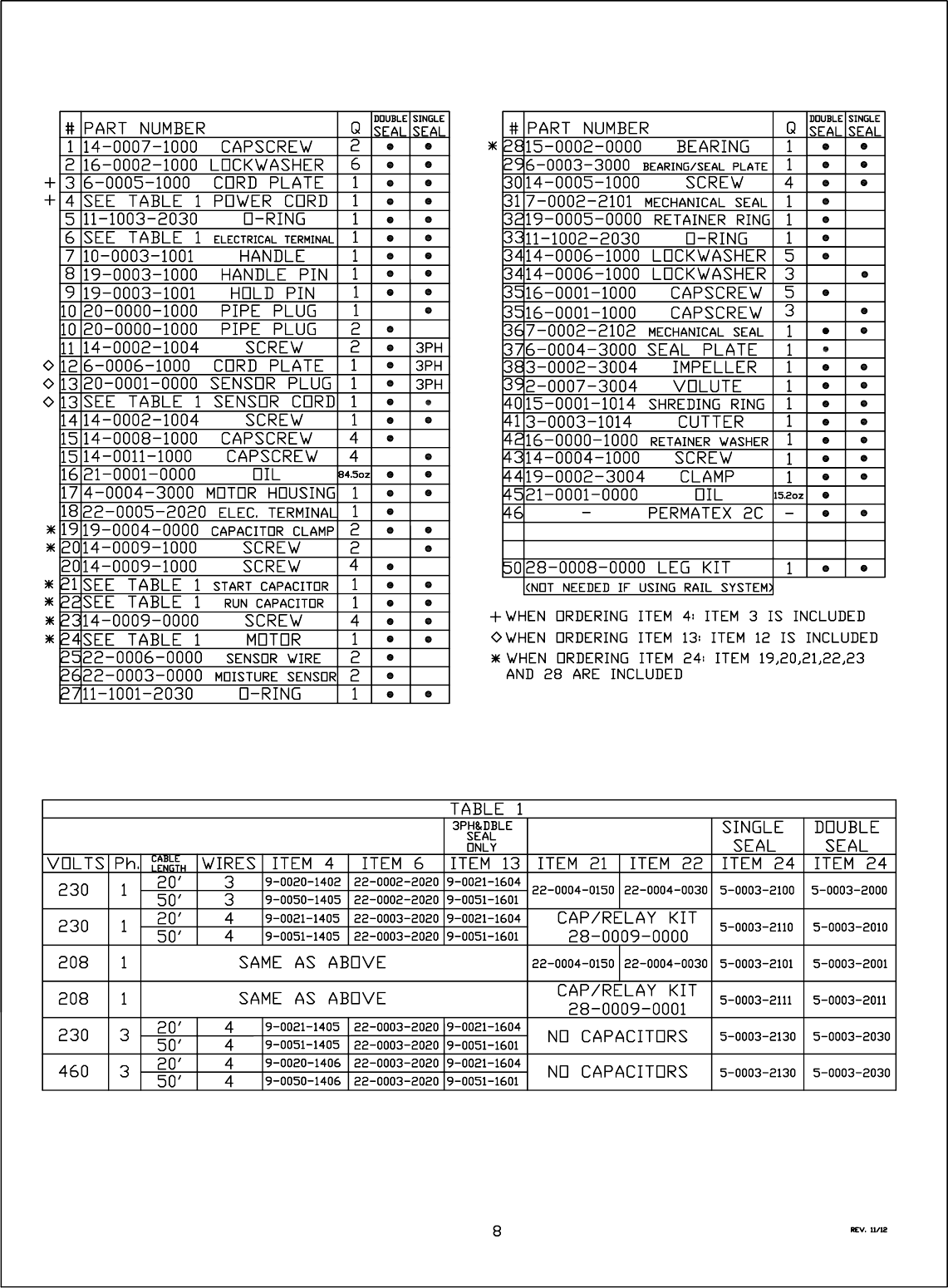
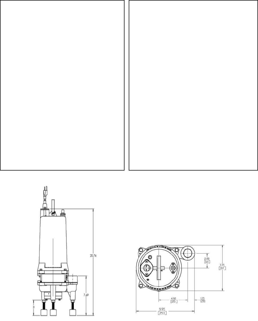
Specifications
Page 9
DISCHARGE………………………..1-1/4" NPT. Vertical
SOLIDS HANDLING……………………………………3”
LIQUID TEMP……..……150 DEG. F. INTERMITTENT
MOTOR HOUSING…………………………….Cast Iron
VOLUTE…………………………………………Cast Iron
SEAL PLATE……………………………………Cast Iron
IMPELLER……………………………………… Cast Iron
SHAFT……………………………….416 Stainless Steel
MOTOR……. ( 1 PHASE) 3450 RPM. 60 Hz NEMA L
Includes Overload Protection In The Motor
Oil Filled, Class F Insulation
Capacitor Start / Capacitor Run
CPG-DSL Models – Capacitors & Protection
In Control Panel
(3 PHASE) 3450 RPM 60Hz NEMA B
Requires Overload Protection In Panel
OPTIONAL SEAL FAILURE……20’ Length Standard
UL / CSA (SJTW) 16/3 (.330OD)
WEIGHT………………….85 lbs Manual (Double Seal)
……………………75 lbs Manual
(
Sin
g
le Seal
)
SHAFT SEAL - (SINGLE SEAL)
Silicon Carbide-Silicon Carbide
Buna-N- Elastomer
300 Series Stainless Steel - Hardware
SHAFT SEAL - (DOUBLE SEAL)
Tandem Double Mechanical
Upper / Carbon-Ceramic
Lower/ Silicon Carbide-Silicon Carbide
Buna-N- Elastomer
300 Series Stainless Steel - Hardware
BEARING (UPPER & LOWER
Single Row, Ball. Oil Lubricated
HARDWARE…………………316 Series Stainless Steel
O-RINGS……………………………………………..Buna-N
CORD…............................................20' Length Standard
UL / CSA (SJOW) 14ga (.375OD)
UL / CSA (SO) 14ga (.60 OD) 460Volt
CORD ENTRY………….Quick Disconnect Pin Terminals

Page 11
Start-Up Report / Warranty Registration
Please fill out the following questions as completely and accurate as possible. Please
mail to Champion Pump Company, Inc. – P. O. Box 528 – Ashland, OH 44805.
REPORTS THAT ARE NOT RETURNED CAN DELAY OR VOID WARRANTY.
Pump Owner’s
Name:__________________________________________________________________
Address:________________________________________________________________
Location of installation:____________________________________________________
Phone:__________________________________________________________________
Purchased from:__________________________________________________________
Pump Model_______________Serial #__________________Date Code:_____________
NOTE: CPG2022DSL MODELS MUST HAVE CAPACITOR KIT #28-0009-0000 OR
WARRANTY IS VOID.
Date Installed:____________________________________________________________
Does impeller turn freely by hand? YES____________NO___________________
Condition of cord jacket? Good________Fair________________Poor_____________
Was equipment stored?___________How long?_________________________________
Liquid being pumped______________________________________________________
Debris in bottom of station?________Was debris removed in your presence?__________
Discharge pipe size?___________ Length of pipe?_________Static lift?_____________
Does station appear to operate at the proper rate?_______Pump down time?___________
Voltage At Wiring Terminal L1-L2___________L2-L3___________L1-L3___________
Run Amps L1_______________L2_______________L3_______________
3 Phase Models – Check Proper Rotation? Yes / NO
Difficulties during start up: _________________________________________________
________________________________________________________________________
________________________________________________________________________
________________________________________________________________________
________________________________________________________________________
I certify this report to be accurate (start up person)_______________________________
Employed by___________________________________ Date: ____________________
