Chantry Networks BP100 BP100S AND BP100E User Manual Chantry Installation BP July4
Chantry Networks Inc. (a Siemens Company) BP100S AND BP100E Chantry Installation BP July4
USERS MANUAL

Chantry
BeaconWorks
Installation Guide
BeaconPoint
In this document
Unpacking and Mounting the BeaconPoint.... 2
Connecting and Powering the BeaconPoint .. 3
Caution ………………………………………….4
Unpacking and Mounting the BeaconPoint
Chantry Networks Inc. BeaconPoint Installation Guide Page 2
Copyright 2003. All rights reserved.
Unpacking and Mounting the BeaconPoint
Unpack the BeaconPoint from its carton.
Also in the carton are the following:
• one wall bracket
• one allen key (to depress security latch)
• one plastic spreading rivet and matching
plastic screw (to secure BeaconPoint to
bracket
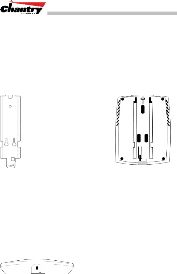
1. Mount the BeaconPoint
wall bracket, using 3 screws. For
a typical dry wall mounting, use #6
X 1 inch pan head sheet metal
screws with # 6 plastic wall
anchors.
Make sure the top of the bracket
is near the LAN ethernet cable
plug coming from the wall.
2. Press the back of the
BeaconPoint onto the
bracket, aligning it
with the open notches
in the bracket.
Then slide it downwards
until it click into place.
↑
Channel for allen key to
spring clip
Security Note #1: A small spring clip on the BeaconPoint case has now
snapped into an opening in the bracket. To remove the BeaconPoint
from the bracket, insert the allen key (provided) into a small hole at the
bottom of the bracket. Use the allen key to depress the spring clip. Then
you can slide the case up the bracket and lift off the BeaconPoint.
Opening for rivet
↓
↑
Opening for allen key
3. Insert the plastic spreading rivet
through the hole at the bottom of the
bracket and into the BeaconPoint
case. Then screw in the plastic screw.
This spreads the rivet and locks the
case to the bracket.
Security Note #2: The spreading rivet prevents casual removal of the
BeaconPoint. You will need a screwdriver to remove it.

Connecting and Powering the BeaconPoint
Chantry Networks Inc. BeaconPoint Installation Guide Page 3
Copyright 2003. All rights reserved.
Connecting and Powering the BeaconPoint
[Optional].
Connect an
AC/DC power
supply (if PoE
is not being
used in your
network)
↑ ↑
power LAN ethernet
connector port connector
In the top of the
BeaconPoint, connect
the LAN ethernet
cable to the ethernet
port.
Power by AC Adaptor
If you wish to use an AC power adaptor, the specified adaptor is Ault:
PW117RA0503B01 [Input: 120-240 VAC, Output Voltage DC 5 V, max
amps 2.00, max watts 10]. The adaptor is not provided with the
BeaconPoint.
Install the adaptor within six feet of a wall outlet, attach it to the
BeaconPoint and then plug the adaptor into a wall outlet.
Power Over the Ethernet
If your network is already set up with PoE, attach the LAN ethernet
cable to RJ45 ethernet connector in the top of the BeaconPoint.
Power Over the Ethernet: Adding PoE Injector
To provide power for a BeaconPoint using the ethernet cable (if this is
not set up on your LAN network), you will need a PoE injector (Ault:
PW130RA480N01) that provides power to the ethernet cable. The PoE
injector is not provided with the BeaconPoint.

Caution
Chantry Networks Inc. BeaconPoint Installation Guide Page 4
Copyright 2003. All rights reserved.
Caution
This equipment has been tested and found to comply with the limits for
a Class B digital devices, pursuant to Part 15 of the FCC Rules. These
limits are designed to provide reasonable protection against harmful
interference in a residential installation. This equipment generates,
uses, and can radiate radio frequency energy and, if not installed and
used in accordance with the instruction manual, may cause harmful
interference to radio communications. However, there is no guarantee
that interference will not occur in a particular installation. If this
equipment does cause harmful interference to radio or television
reception, which can be determined by turning the equipment off and
on, the user is encouraged to try to correct the interference by one of
more of the following measures:
• Reorient or relocate the receiving antenna
• Increase the separation between the equipment and receiver
• Connect the equipment into an outlet on a circuit different from
that to which the receiver is connected.
• Consult the dealer or an experienced radio/TV technician for
help.
WARNING: Changes or modifications not expressly approved
by Chantry Networks could void the user’s authority to operate the
equipment
WARNING: To satisfy FCC RF exposure requirements for mobile
transmitting devices, a separation distance of 20 cm or more should be
maintained between the antenna of this device and persons during
device operation. To ensure compliance, operations at closer than this
distance is not recommended. The antenna used for this transmitter
must not be co-located in conjunction with any other antenna or
transmitter.