ChargePoint CT21002000-01 CT2100/2000 ChargePoint Networked Charging Station User Manual CT2000 Installation Guide
ChargePoint, Inc. CT2100/2000 ChargePoint Networked Charging Station CT2000 Installation Guide
Contents
- 1. Users Manual CT2000
- 2. Users Manual CT2100
Users Manual CT2000

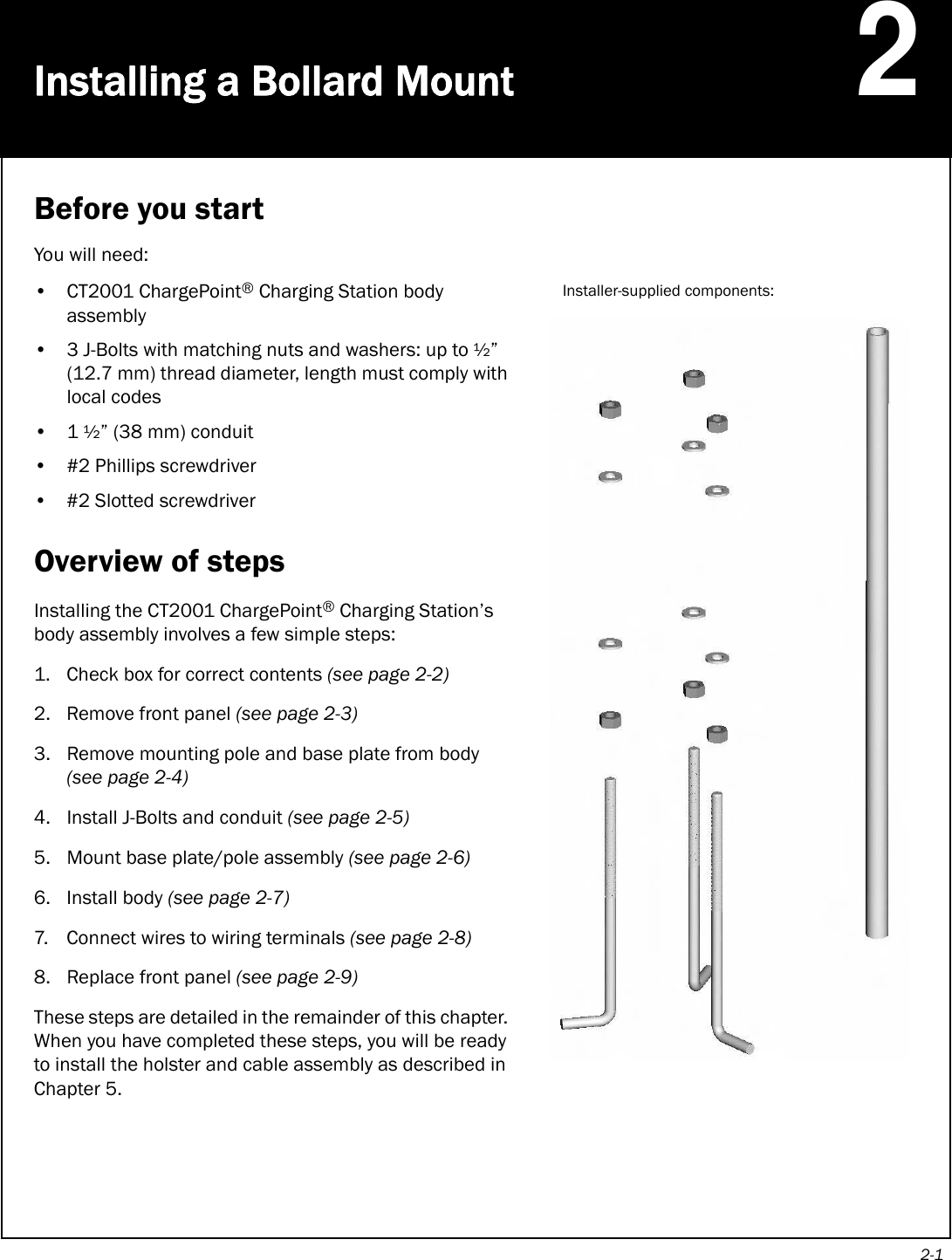
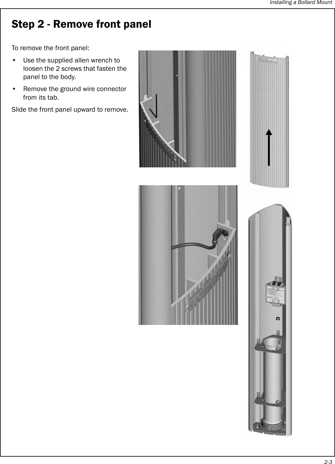
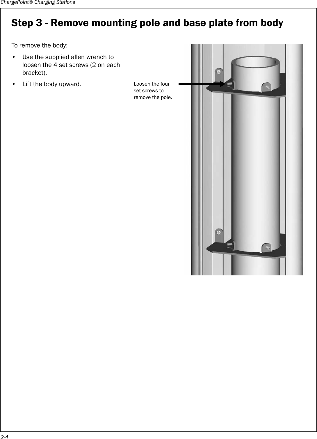
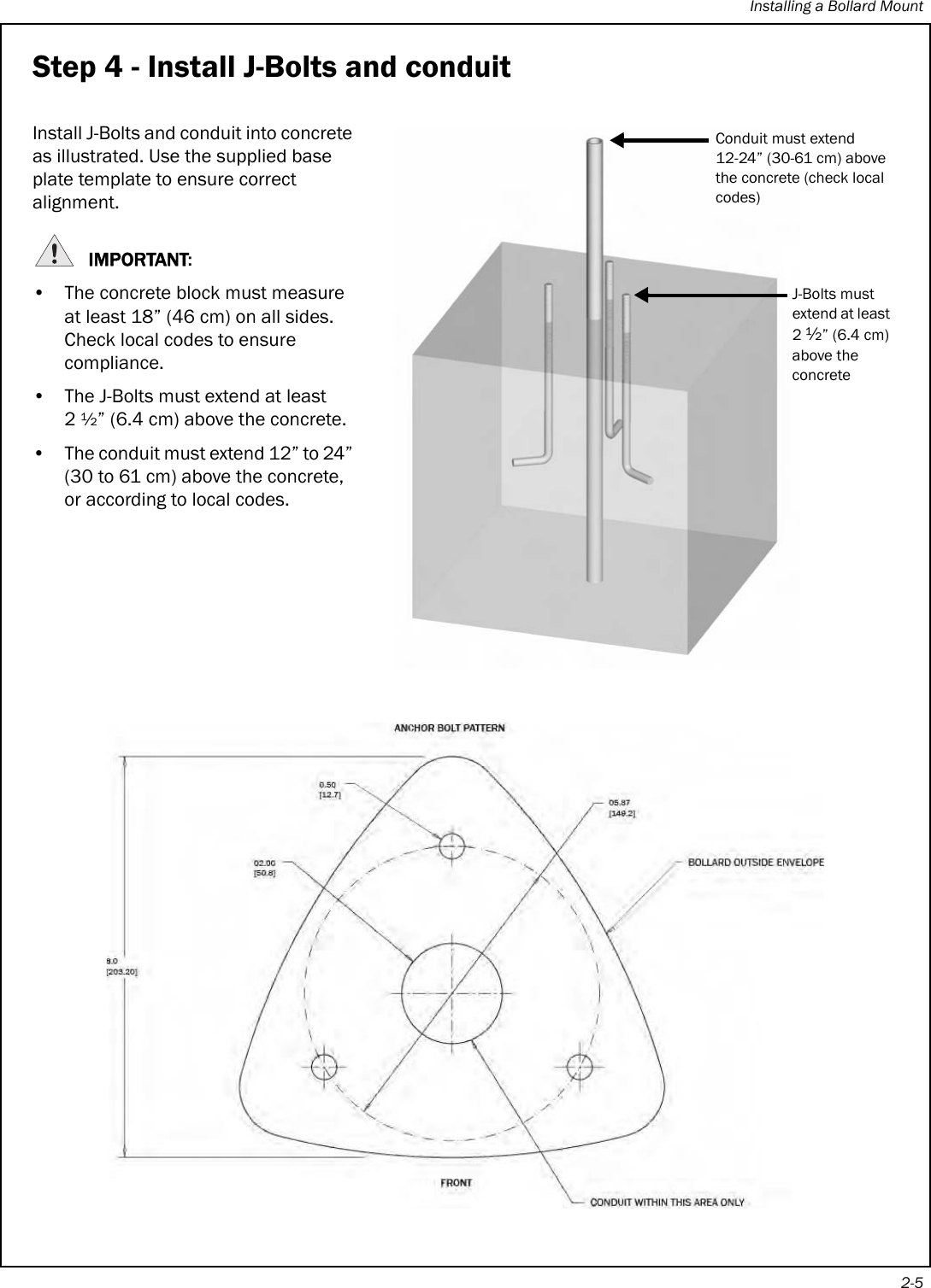
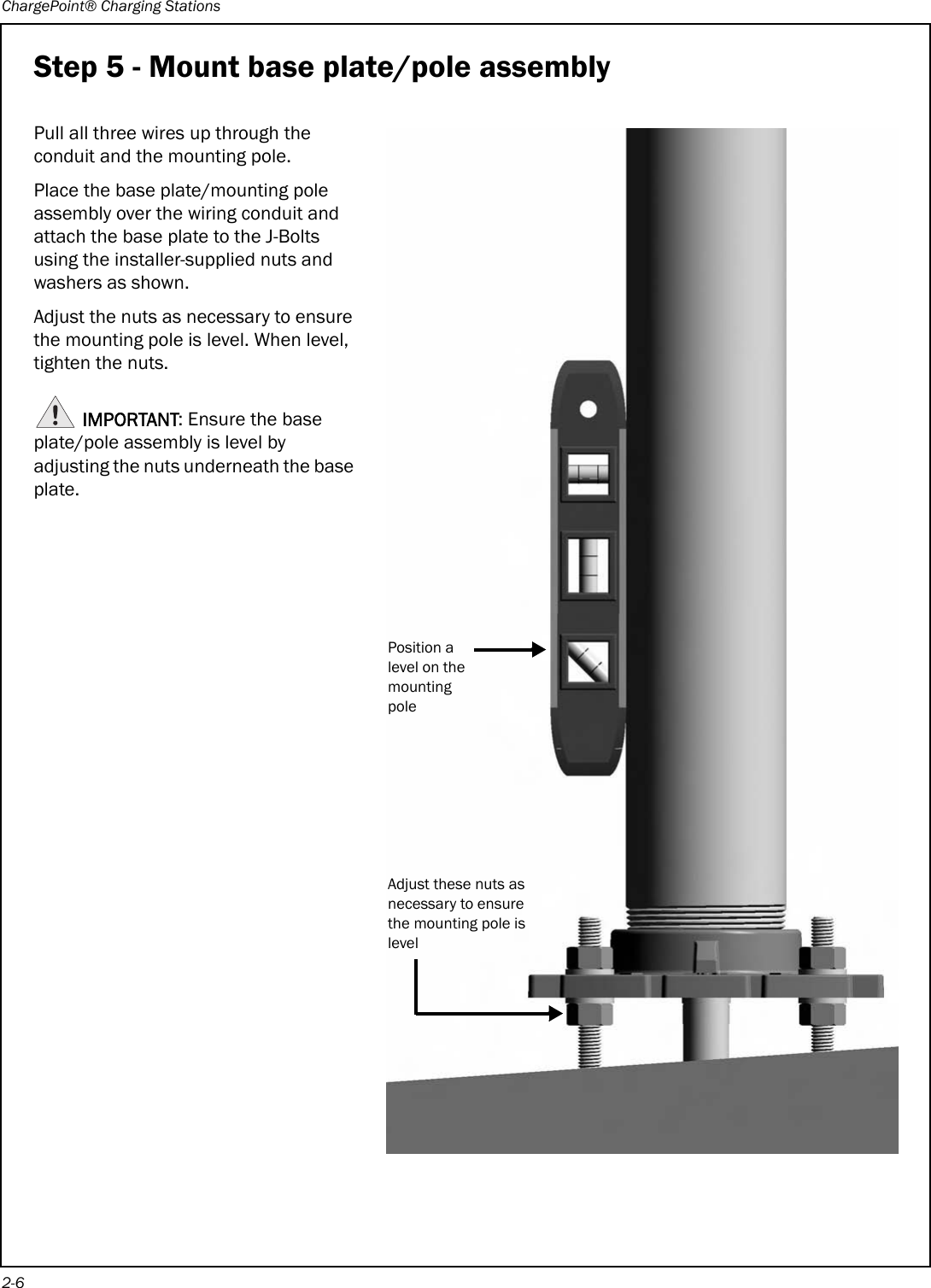
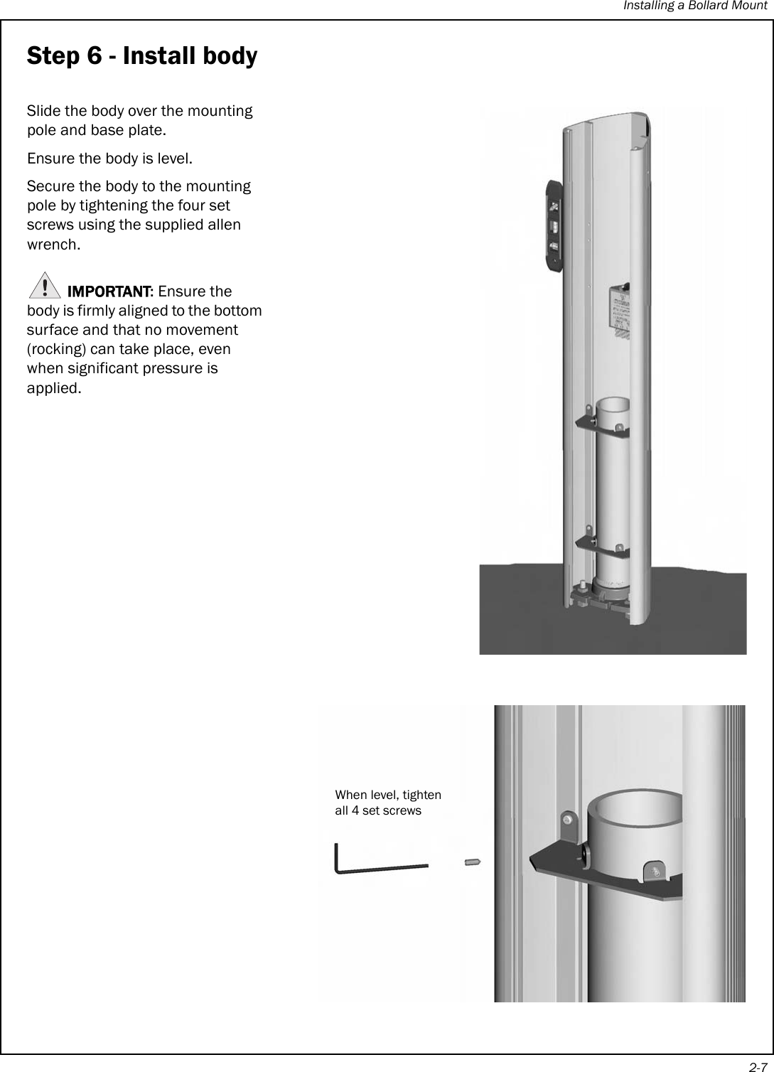
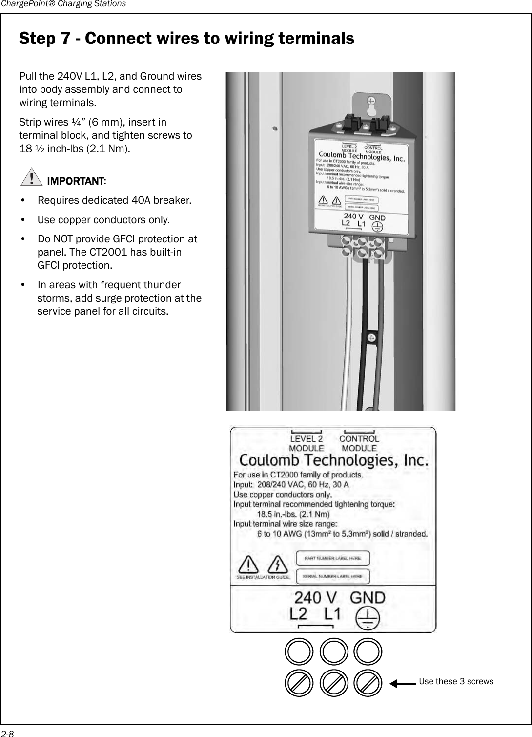
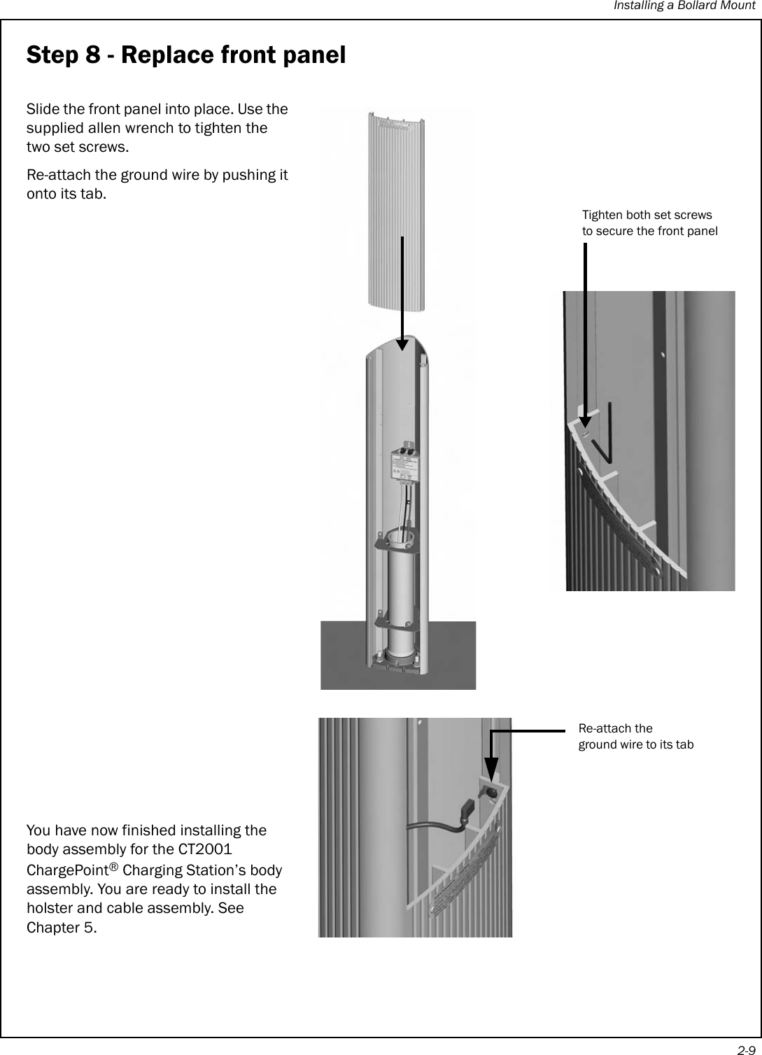
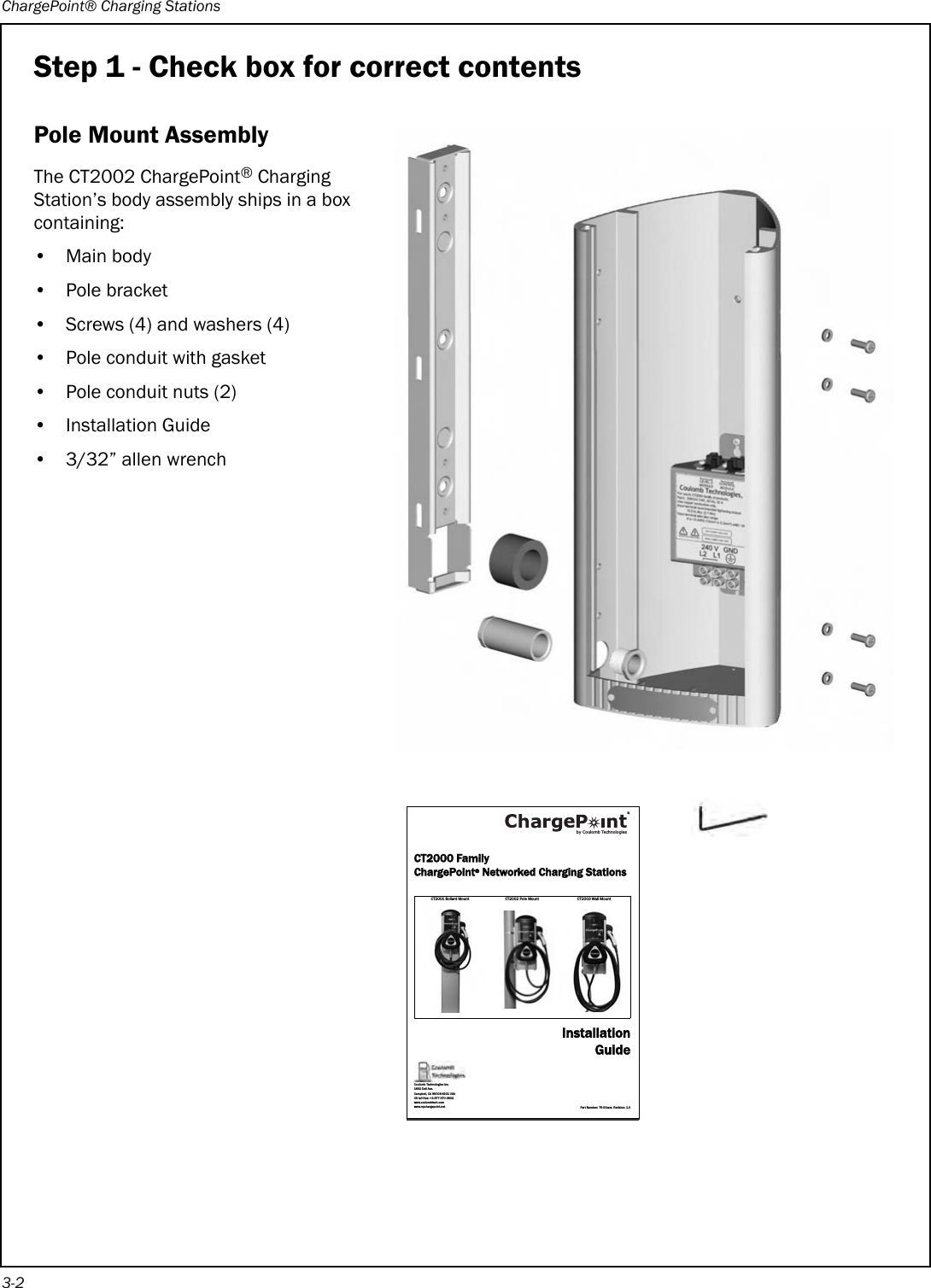
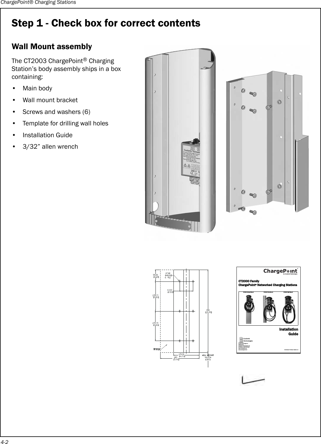
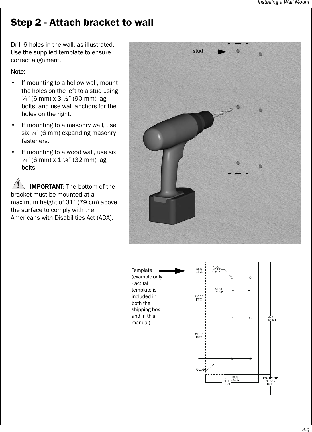
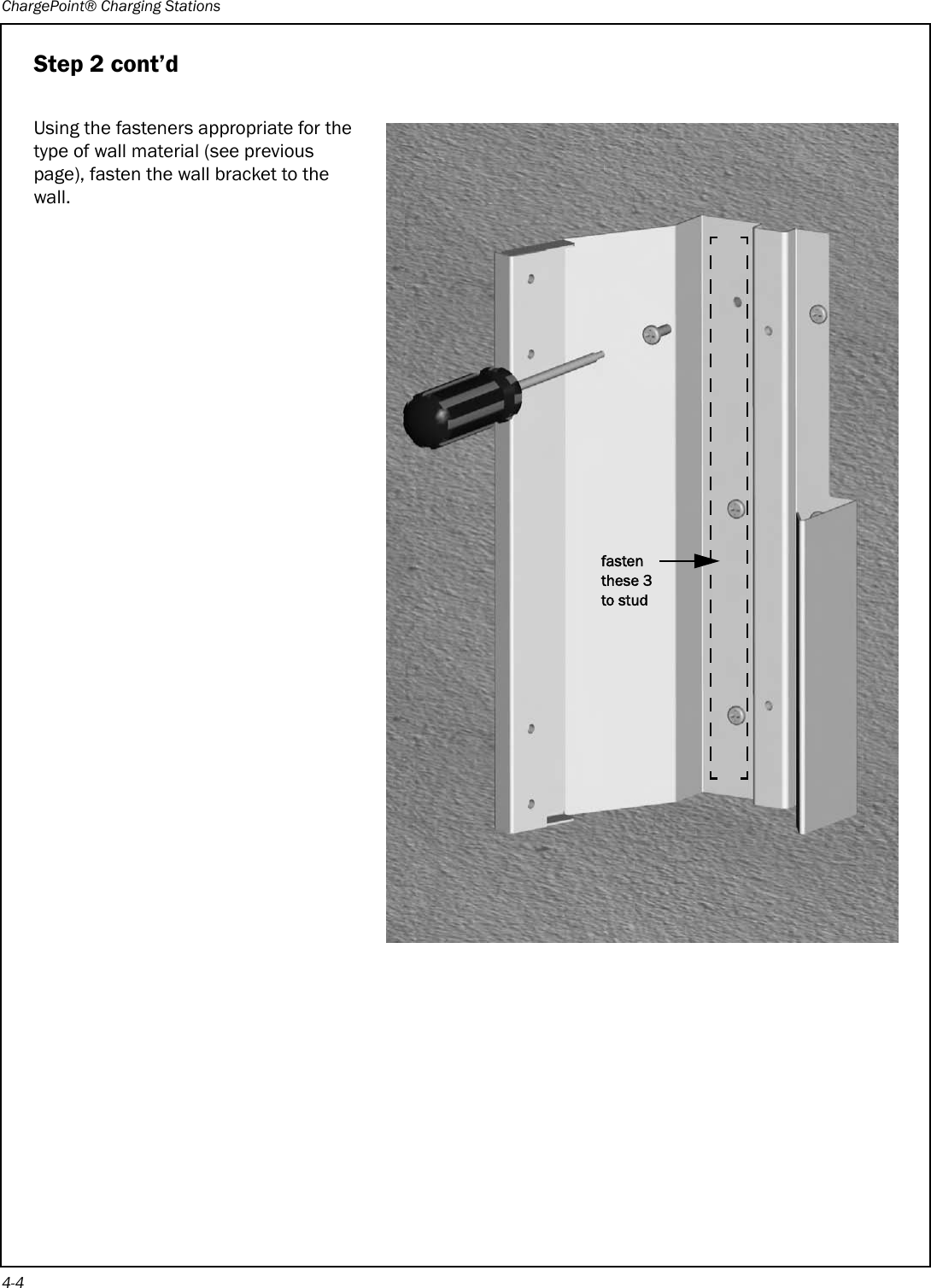
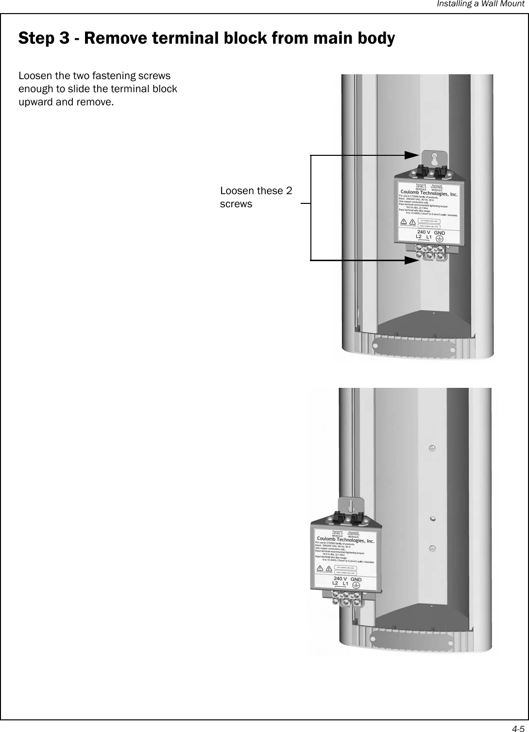
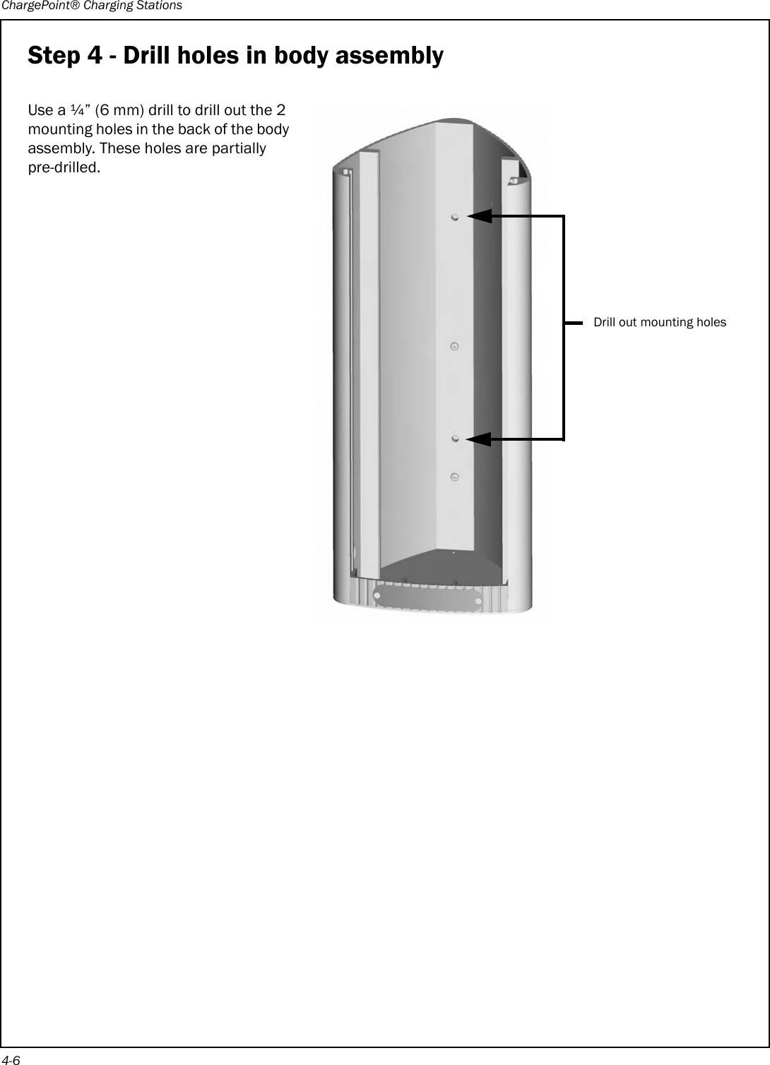
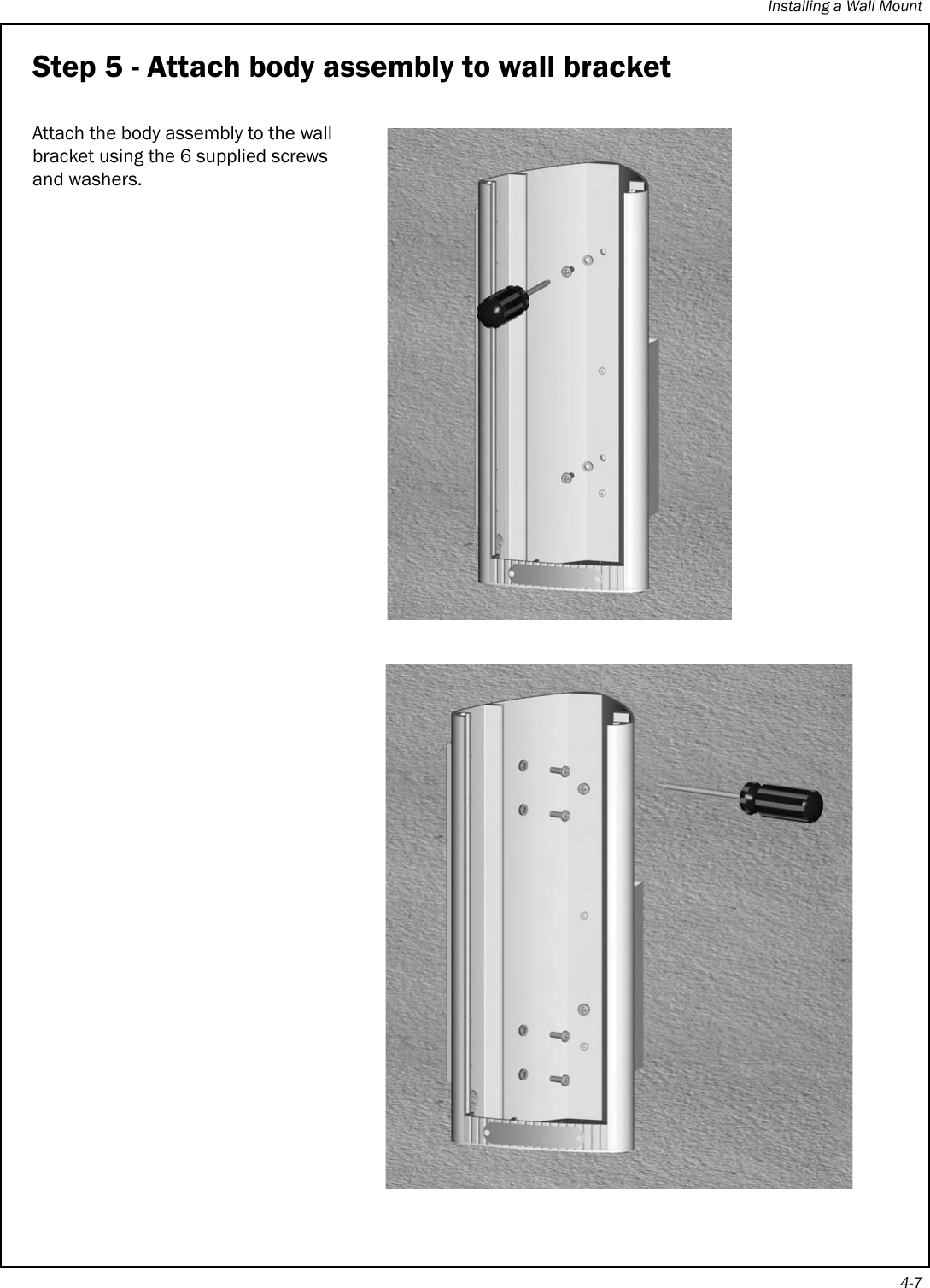
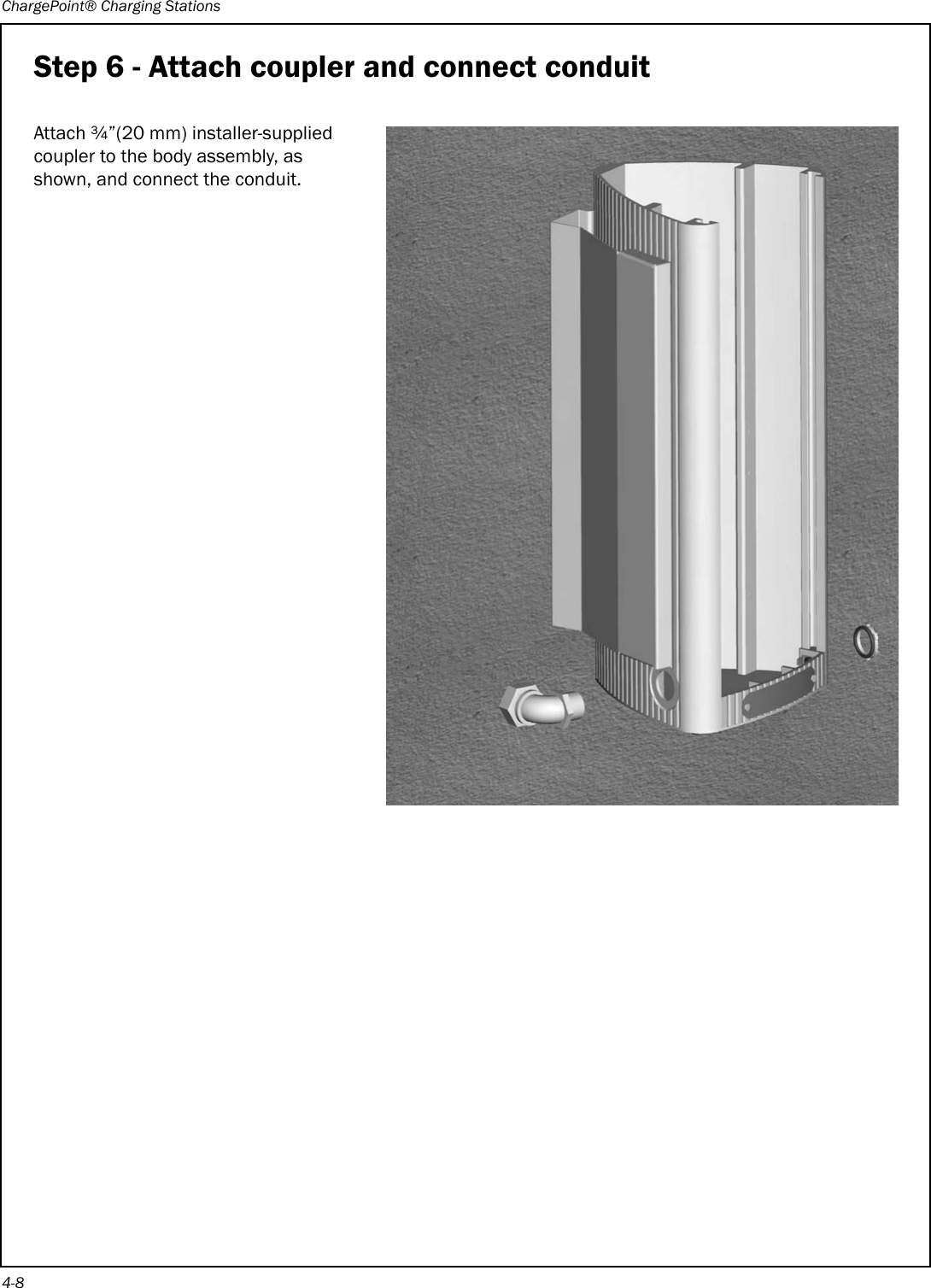
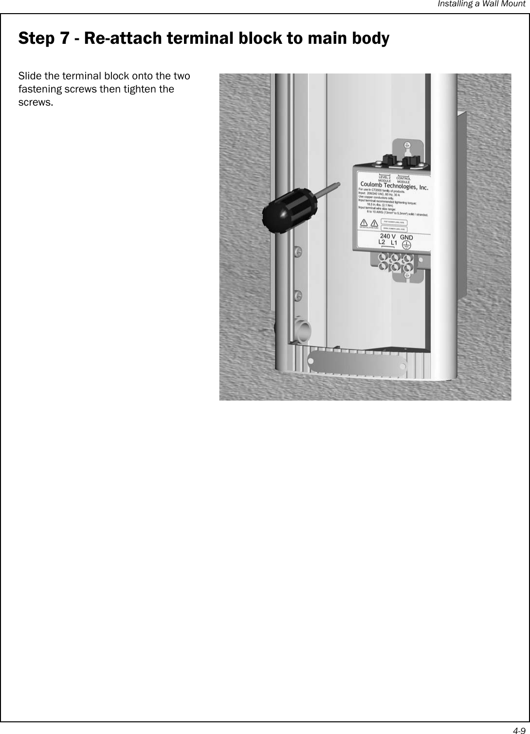
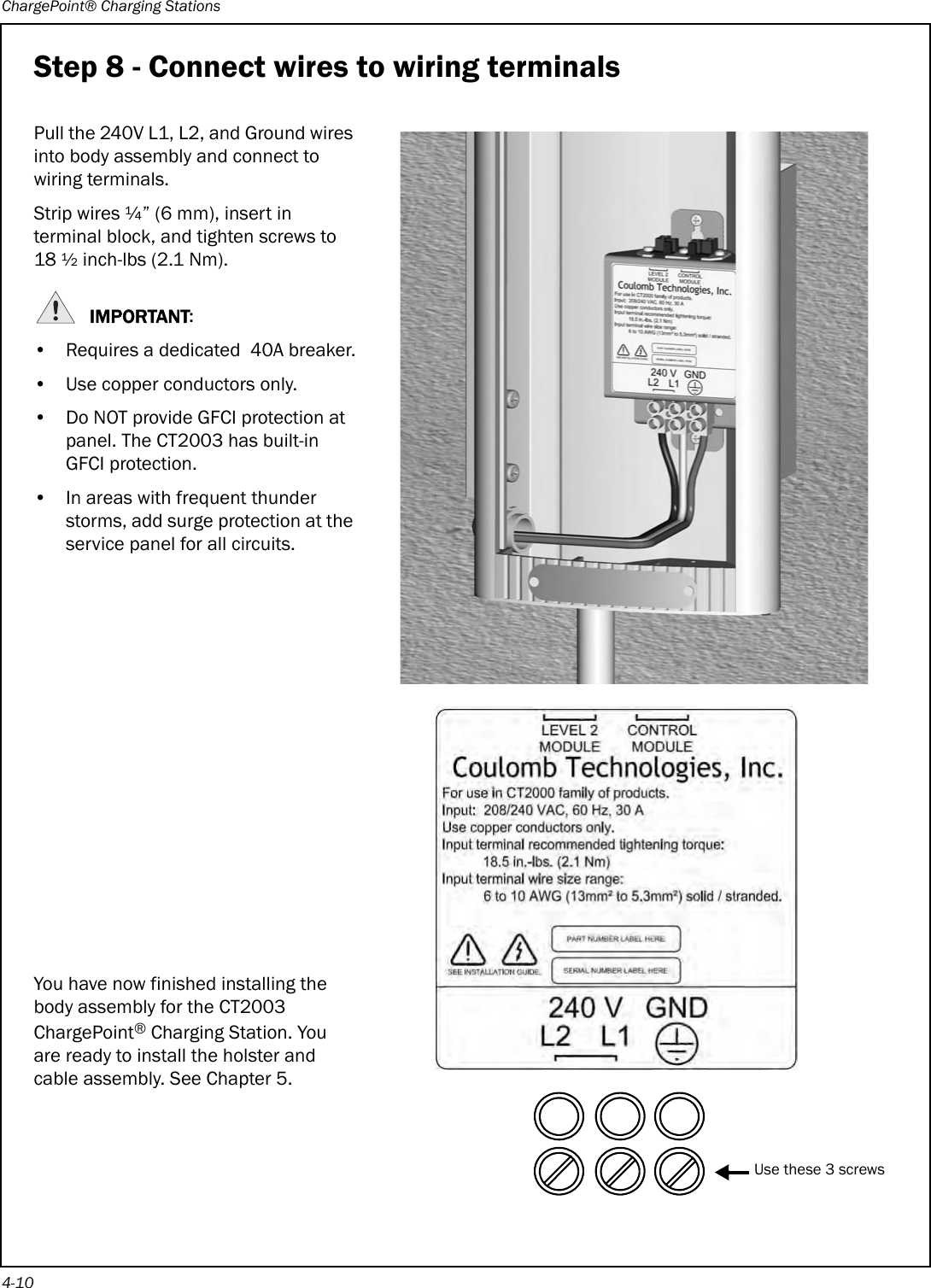
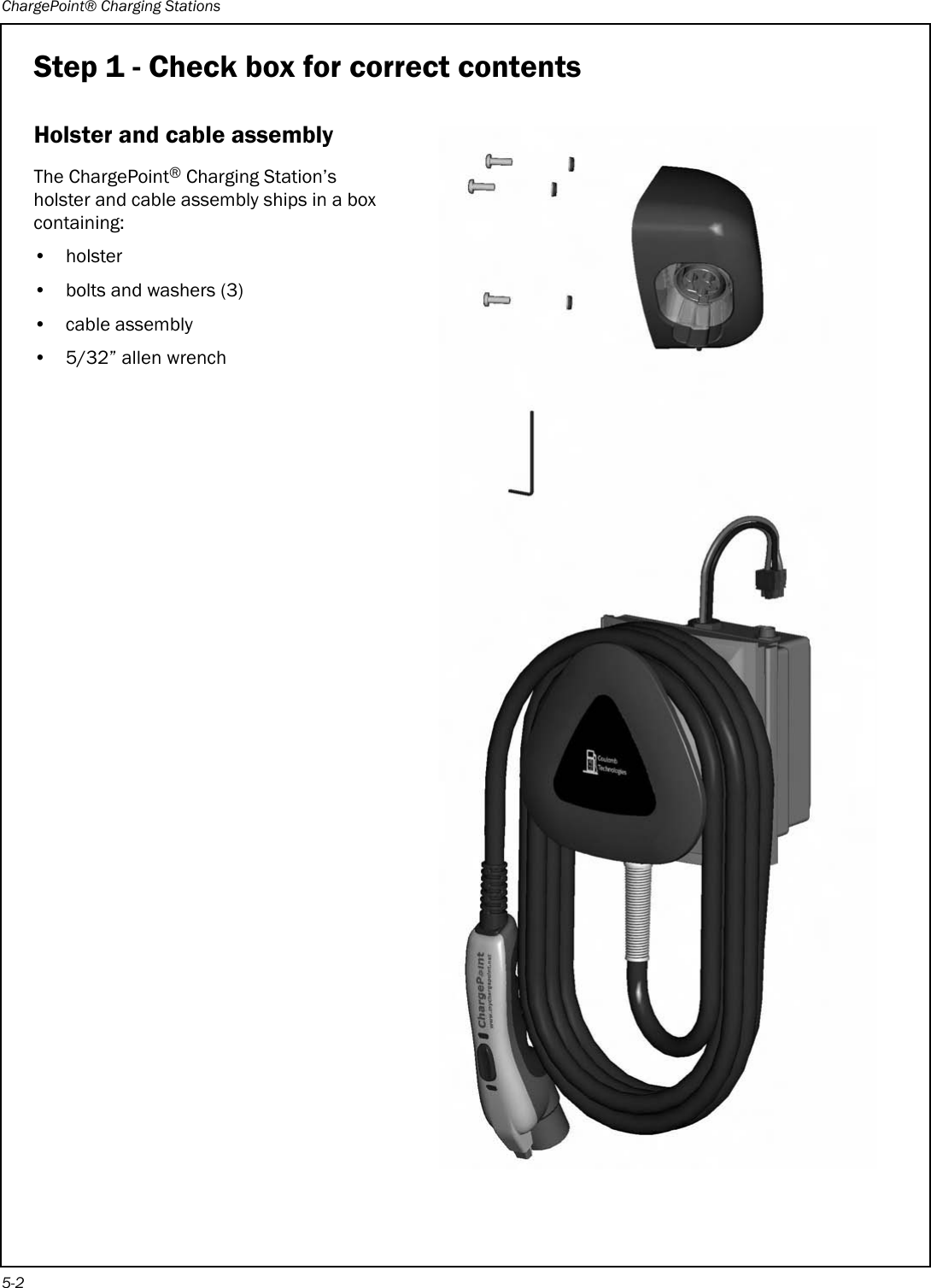
![ChargePoint® Charging Stations2-2Step 1 - Check box for correct contentsBollard Mount AssemblyThe CT2001 ChargePoint® Charging Station’s body assembly ships in a box containing:• Main body assembly (including body, front panel, mounting pole, and base plate)• Base plate template• Installation Guide• 3/32” allen wrenchFRONTANCHOR BOLT PATTERNCONDUIT WITHIN THIS AREA ONLYBOLLARD OUTSIDE ENVELOPE0.50[12.7]02.00[50.8]8.0[203.20]05.87[149.2]CT2000 FamilyChargePoint® Networked Charging StationsCT2001 Bollard Mount CT2002 Pole Mount CT2003 Wall MountInstallationGuidePart Number: 75-00xxxx Revision: 1.0Coulomb Technologies Inc.1692 Dell Ave.Campbell, CA 95008-6901 USAUS toll free: +1-877-370-3802www.coulombtech.comwww.mychargepoint.netby Coulomb Technologies® FrontpanelBody Mounting poleBase plateThe body, front panel, mounting pole, and base plate are pre-assembled](https://usermanual.wiki/ChargePoint/CT21002000-01.Users-Manual-CT2000/User-Guide-1355591-Page-10.png)