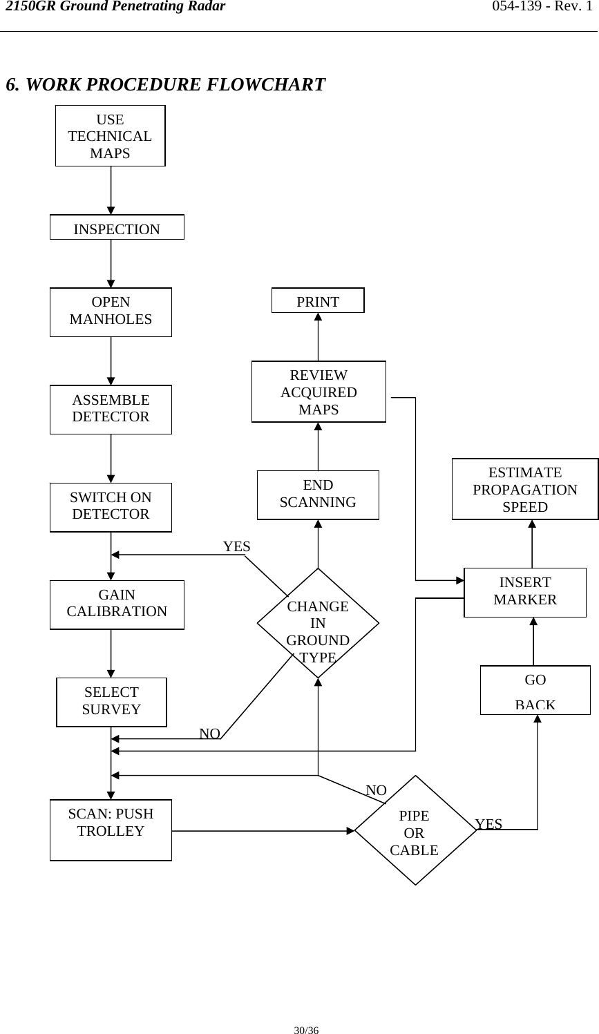
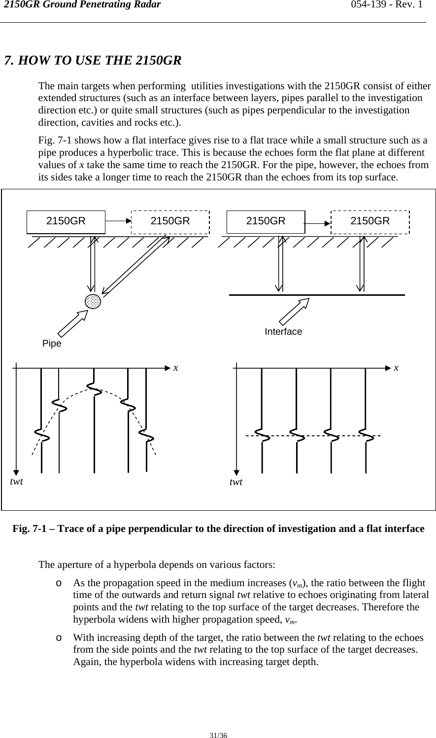
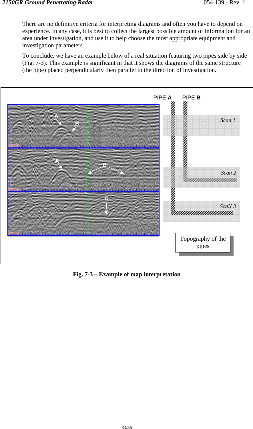
Charles Machine Works The 2150GR700 Ground Penetrating Radar User Manual 2150GR Manual Rev 1

Charles Machine Works Inc, The Ground Penetrating Radar 2150GR Manual Rev 1

Users Manual

    Rev. 1 054-139     2150GR Ground Penetrating Radar User Guide
2150GR Ground Penetrating Radar 054-139 - Rev. 1  ii / ii  INDEX 1. INTRODUCTION................................................................................................................... 1 1.1 Scope................................................................................................................................ 2 1.2 Trademarks...................................................................................................................... 2 1.3 Acronyms and Definitions ............................................................................................... 2 1.3.1 Acronyms............................................................................................................................2 1.3.2 Definitions...........................................................................................................................2 2. OVERVIEW ............................................................................................................................ 3 2.1 How to use this manual ................................................................................................... 3 2.2 Background knowledge required..................................................................................... 3 3. USER GUIDE.......................................................................................................................... 4 3.1 Description of the hardware............................................................................................ 4 3.1.1 The Radar Control Unit ......................................................................................................5 3.1.2 The Antenna........................................................................................................................6 3.1.3 Power supply.......................................................................................................................7 3.1.3.1 Charge level and battery replacement ....................................................................7 4. ASSEMBLY PROCEDURE................................................................................................... 8 4.1 How to assemble the trolley............................................................................................. 8 4.2 Connecting the cables.................................................................................................... 10 4.2.1 Connecting the battery......................................................................................................10 4.2.2 Mounting the antenna and connecting its cables .............................................................11 4.2.3 Mounting the PC notebook...............................................................................................12 4.2.4 Connecting the position sensor.........................................................................................13 4.2.5 Removing the trolley wheels............................................................................................14 5. THE ACQUISITION SOFTWARE .................................................................................... 15 5.1 Basic characteristics of the notebook PC...................................................................... 15 5.2 Software installation and configuration........................................................................ 16 5.3 The operational phases.................................................................................................. 18 5.3.1 Running the software........................................................................................................18 5.3.2 Pre-acquisition commands................................................................................................19 5.3.3 Commands used during acquisition .................................................................................20 5.3.4 Depth calibration...............................................................................................................24 5.3.5 Post-acquisition commands..............................................................................................25 5.4 Error messages..............................................................................................................29 6. WORK PROCEDURE FLOWCHART .............................................................................. 30 7. HOW TO USE THE 2150GR............................................................................................... 31 APPENDIX A - THE PRELIMINARY INVESTIGATION................................................. 34 APPENDIX B - THE TECHNICAL MAPS ........................................................................... 34 APPENDIX C - OPENING MANHOLES.............................................................................. 35 APPENDIX D - CARE, MAINTENANCE AND SAFETY WARNINGS ........................... 35 APPENDIX E - CLEANING INSTRUCTIONS .................................................................... 36
2150GR Ground Penetrating Radar 054-139 - Rev. 1  iii / iii   FIGURES INDEX FIG. 3-1 – OVERVIEW OF THE 2150GR AND ITS COMPONENTS.........................................................4 FIG. 3-2 – THE CONTROL UNIT ...................................................................................................................5 FIG. 3-3 – THE ANTENNA-CONTROL UNIT CONNECTION CABLE.....................................................5 FIG. 3-4 – THE INVERTED NETWORK CABLE .........................................................................................5 FIG. 3-5 – THE POWER SUPPLY CABLE.....................................................................................................5 FIG. 3-6 – ATS ANTENNA..............................................................................................................................6 FIG. 3-7 – LEAD BATTERY............................................................................................................................7 FIG. 3-8 – BATTERY STATUS SIGNAL (LEFT) AND THE BATTERY CHARGER (RIGHT)...............7 FIG. 4-1 – TROLLEY FOLDED IN ITS CARRIER BAG..............................................................................8 FIG. 4-2 – OPENING THE TROLLEY............................................................................................................9 FIG. 4-3 – HANDLE BLOCKING MECHANISM..........................................................................................9 FIG. 4-4 – BATTERY AND CABLING SUPPORT......................................................................................10 FIG. 4-5 – CONNECTING THE ANTENNA ................................................................................................11 FIG. 4-6 – ANTENNA-RADAR CONNECTION..........................................................................................11 FIG. 4-7 – MOUNTING THE NOTEBOOK PC............................................................................................12 FIG. 4-8 – CONNECTING THE POSITION SENSOR.................................................................................13 FIG. 4-9 – REMOVING THE TROLLEY WHEELS ....................................................................................14 FIG. 5-1 – SELECTING THE ETHERNET CARD (TCP/IP).......................................................................16 FIG. 5-2 – CHANGING THE IP ADDRESS .................................................................................................17 FIG. 5-3 – ACQUISITION SOFTWARE ICON ............................................................................................18 FIG. 5-4 – INITIALIZING WINDOW ...........................................................................................................18 FIG. 5-5 – START CALIBRATION...............................................................................................................19 FIG. 5-6 – ACQUISITION SELECTION WINDOW....................................................................................20 FIG. 5-7 – NEW ACQUISITION WINDOW.................................................................................................20 FIG. 5-8 – RADAR MAP DURING THE ACQUISITION PHASE .............................................................21 FIG. 5-9 – IDENTIFYING A TARGET .........................................................................................................22 FIG. 5-10 – THE ANTENNA CENTER POINT............................................................................................22 FIG. 5-11 – UP/DOWN FUNCTION..............................................................................................................23 FIG. 5-12 – ICONS FOR TYPES OF PIPES AND CABLES .......................................................................23 FIG. 5-13 – DELETING A SURVEY.............................................................................................................25 FIG. 5-14 – HOW TO RENAME A SURVEY...............................................................................................26 FIG. 5-15 – INSERTION OF A MARKER DURING THE REVIEW PHASE............................................26 FIG. 5-16 – PRINT FUNCTION.....................................................................................................................27 FIG. 5-17 – FINAL PRINTOUT OF A RADAR MAP..................................................................................28 FIG. 7-1 – TRACE OF A PIPE PERPENDICULAR TO THE DIRECTION OF INVESTIGATION AND A FLAT INTERFACE...............................................................................................................................31 FIG. 7-2 – MAPS SHOWING TRACES OF AN INTERFACE AND PIPES PERPENDICULAR TO THE DIRECTION OF INVESTIGATION....................................................................................................32 FIG. 7-3 – EXAMPLE OF MAP INTERPRETATION .................................................................................33
2150GR Ground Penetrating Radar 054-139 - Rev. 1  1/36 1. INTRODUCTION The 2150GR is an innovative system capable of detecting tubes and both metallic and non metallic cables buried underground. Following standard radar principles, the 2150GR uses a high performance electromagnetic sensor equipped with electromagnetic transmitters and receivers. The groundbreaking control unit is extremely compact and lightweight at just 2.2 lb (1kg), and is compatible with 700MHz and 250MHz frequency antennas. The simplicity of this instrument means that a brief training course is sufficient for correct use. The simple acquisition software and automatic data saving procedures operate well on Windows 2000 Professional and Windows XP Professional. (For details on the required characteristics of the notebook PC, see Paragraph 5.1.) From an operative point of view, the 2150GR can perfectly adapt to all applications for pipe and cable detection in a typical roadworks environment, both over smooth and rough ground.   SAFETY INFORMATION  The equipment conforms to the following requirements set by EC regulations, including subsequent modifications, and to the legislation set by the member states that implement these regulations:   73/23/EEC Low Voltage Directive 89/336/EEC EMC Directive  Warning: this equipment is destined for use in industrial environments (Class A apparatus). In residential, commercial and light industry environments, this apparatus may generate radio interference: in this case, the user may be required to operate while taking appropriate countermeasures.  This equipment complies with part 15 of the FCC rules. Any changes or modifications not expressly approved by the manufacturer could void the user’s authority to operate the equipment.   !  NOTE   The apparatus is sensitive to the presence of external electromagnatic fields, which may reduce its performance.
2150GR Ground Penetrating Radar 054-139 - Rev. 1  2/36 1.1 Scope This document describes how to use the 2150GR Ground Penetrating Radar, including hardware and software components. 1.2 Trademarks  WINDOWS 2000 PROFESSIONAL /WINDOWS XP PROFESSIONAL  Microsoft Corporation  2150GR  1.3 Acronyms and Definitions 1.3.1 Acronyms 2150GR: single antenna pipe detection system. 1.3.2 Definitions Antenna trolley: a unit that holds all the equipment necessary for acquisition in the field.  Centerpoint : the ideal point of the trolley, situated in the center of the box containing the antenna; it represents the starting point for all scans. Data processing: this is applied to the raw data to permit the acquired sections to be viewed in a comprehensible way. Field survey: a group of field acquisitions relating to a single survey. Handle: a retractable handle gripped by the operator to move the antenna trolley. Maps: graphics showing the change in received radar signal (signal intensity in gray scale) with respect to the scanning direction.  Position sensor: a distance measurement device fixed inside one of the trolley wheels, which constantly signals the distance traveled from the start of the scan back to the Control Unit. Raw data: unprocessed data obtained during a field survey. Receiver: part of the antenna dedicated to detecting the signals. It is housed in the same container as the transmitter. Scan: a single movement of the antenna trolley from the beginning to the end of a pre-established path.  Setup: initialization of a piece of equipment or a software process. Survey: the name given to a collection of scans, which together cover all the areas of a large investigation: typically an entire town or a large urban area. Transmitter: part of the antenna dedicated to emitting the radar signals. It is housed in the same container as the receiver. Utilities: the objects the Subsite searches for, i.e. pipes supplying gas and water, electricity cables, etc.
2150GR Ground Penetrating Radar 054-139 - Rev. 1  3/36 2. OVERVIEW 2.1 How to use this manual  This 2150GR user manual is subdivided as follows: • Chap. 1: Introduction • Chap. 2: Overview • Chap. 3: User guide • Chap. 4: Assembly procedure • Chap. 5: The acquisition software • Chap. 6: Work procedure flowchart • Chap. 7: How to use the 2150GR 2.2 Background knowledge required The following background knowledge is required to be able to use the 2150GR: ¾ Windows 2000 Professional or Windows XP Professional operating system. For any difficulties with this aspect, the user should refer to publications available on this topic or the manual provided with the system.
2150GR Ground Penetrating Radar 054-139 - Rev. 1  4/36 3. USER GUIDE 3.1 Description of the hardware The 2150GR consists of the following parts (see Fig. 3-1): • Control unit (1) • Two wheeled trolley used to move the system (2) • Power cable (3) • Inverted network cable (4) • Antenna-Control Unit connection cable (5) • ATS 250 or 700 IDS Antenna (6) • Position sensor (7) • Position sensor connection cable (not shown) • 12V lead battery (see Fig. 3-7) • Notebook computer (see specifications in paragraph 5.1)   Fig. 3-1 – Overview of the 2150GR and its components
2150GR Ground Penetrating Radar 054-139 - Rev. 1  5/36 3.1.1 The 2150GR Control Unit The control unit has the following main functions: ¾ To communicate with the antenna ¾ To communicate with the notebook computer ¾ To pilot the position sensor The control unit (Fig. 3-2) is fitted with the following connection ports: ¾ Power supply port (1): the power supply cable (Fig. 3.5) connects the battery to the Control Unit. The port is marked BATTERY and has a spy light (5) next to it that indicates when the system is powered by the battery. ¾ Network port (2): the inverted network cable (Fig. 3-4) connects the control unit to the notebook PC. This port is marked LAN. ¾ Antenna port (3): the antenna-control unit cable (Fig. 3-3) connects the Control Unit to the antenna. It is marked ANT. 1. ¾ Position sensor port (4): the position sensor is connected to the control unit using the installed cable (not shown). This port is marked WHEEL.          Fig. 3-2 –Control Unit  Fig. 3-3   Antenna-Control Unit Connection Cable  Fig. 3-4 Inverted Network Cable   Fig. 3-5 Power Supply Cable
2150GR Ground Penetrating Radar 054-139 - Rev. 1  6/36  GENERAL CHARACTERISTICS OF THE CONTROL UNIT NUMBER OF CONNECTABLE ANTENNAS 1 VOLTAGE 12V +/- 10% ENVIRONMENT CHARACTERISTICS  IP65 PANEL CONNECTORS  LAN, BATTERY, ANT.1, WHEEL ABSORBED POWER 8W (1 antenna) OPERATING TEMPERATURE   14°F-104°F (-10 / +40 °C) Tab. 3-1 – Control Unit Characteristics    3.1.2 The Antenna The 2150GR system can be used with one of the following antennas (see Fig. 3-6): • ATS 250 for high signal penetration. • ATS 700 for better resolution near the surface.  Fig. 3-6 –ATS Antenna
2150GR Ground Penetrating Radar 054-139 - Rev. 1  7/36 3.1.3 Power supply The Control Unit is powered by : ¾ A lead 12V, 12Ah battery (see Fig 3-7).  Fig. 3-7 – Lead Battery  3.1.3.1 Charge level and battery replacement When the spy light is lit next to the power supply port on the radar, this indicates that the system is powered: if it is not lit, this means that either the cable is not connected correctly or that the battery needs recharged (less than 10V). The battery has a useful life of around 12 hours. When the battery runs down the instrument must be switched off, another battery connected, and the system can be started up again. A battery can be completely recharged in around 3 hours with the appropriate battery charger (see Fig. 3-8 right). A software message on the PC informs the user of the battery charge level with a BATT button (see Fig. 3-8 left), which changes color as follows: ¾ Green if the battery is fully charged ¾ Yellow if it is semi-charged ¾ Red if the battery needs recharged     Fig. 3-8 – Battery status signal (left) and battery charger (right)  !  NOTE  The control unit continuously draws current from the battery. To prevent drain, unplug the battery when the unit is not in use.
2150GR Ground Penetrating Radar 054-139 - Rev. 1  8/36 4. ASSEMBLY PROCEDURE 4.1 How to assemble the trolley Follow the procedure below to assemble the trolley: ¾ Remove the trolley from its bag (Fig. 4-1).  Fig. 4-1 – Trolley folded in its carrier bag
2150GR Ground Penetrating Radar 054-139 - Rev. 1  9/36       Fig. 4-2 – Opening the Trolley  Fig. 4-3 – Handle blocking mechanism  ¾ Open the trolley from the folded position to the upright position by gripping the handle (1) shown in Fig. 4-2 and lifting until the two cylindrical pins (2) click into their supports (3). ¾ Unlock the two tension levers (1) by rotating them outwards and pull the handle (2) upwards, to adjust it as desired (Fig. 4-3). Lock the tension levers when desired height is set.
2150GR Ground Penetrating Radar 054-139 - Rev. 1  10/36 4.2 Connecting the cables 4.2.1 Connecting the battery  Fig. 4-4 – Battery and cabling support ¾ Place the battery in the battery bag and place the bag on the PVC base plate. Secure the bag to the support with the strap provided. ¾ Connect one end of the power supply cable to the BATTERY port on the Control Unit (1). Connect the opposite end to the white connector  on the battery (2), as shown in Fig. 4-4.  !  NOTE  The control unit continuously draws current from the battery. To prevent drain, unplug the battery when the unit is not in use.
2150GR Ground Penetrating Radar 054-139 - Rev. 1  11/36 4.2.2 Mounting the antenna and connecting its cables  Fig. 4-5 – Connecting the Antenna ¾ Place the antenna under the trolley (Fig. 4-5).  ¾ Insert the two trolley pins into the antenna mounts as shown and secure with the nuts provided.  Fig. 4-6 – Antenna-radar connection ¾ Connect one end of the antenna-control unit connection cable to the antenna port (2). Connect the opposite end to the ANT.1 port (1) on the Control Unit (Fig. 4-6).
2150GR Ground Penetrating Radar 054-139 - Rev. 1  12/36 4.2.3 Mounting the PC notebook ¾ The notebook PC is secured to the upper base plate on the trolley with nylon hook and pile strips (shown in Fig. 4-7, left). ¾ Once the notebook is fixed on the plate, connect one end of the inverted network cable to the PC network port (1). Connect the opposite end to the waterproof black connector to the radar port (2) on the control unit.      Fig. 4-7 – Mounting the notebook PC
2150GR Ground Penetrating Radar 054-139 - Rev. 1  13/36 4.2.4 Connecting the position sensor  Fig. 4-8 – Connecting the position sensor  ¾ The system position sensor is situated inside one of the trolley wheels and turns in unison with it (Fig. 4-8). The sensor measures all movements of the 2150GR from its starting point, which coincides with the system centerpoint (which is the center of the antenna). ¾ The sensor cable (2) is connected to the WHEEL port (1) on the Control Unit.
2150GR Ground Penetrating Radar 054-139 - Rev. 1  14/36 4.2.5 Removing the trolley wheels  Fig. 4-9 – Removing the trolley wheels  ¾ If the wheels need to be removed when storing the 2150GR, press the black button labeled PRESS (shown) to the side of the wheel and pull the wheel outward. ¾ To reinsert the wheel onto the axis, it is sufficient to push it into the support until the block clicks into place (Fig. 4-9).   !  NOTE  Remember to disconnect all cables before putting the trolley back into its storage bag.
2150GR Ground Penetrating Radar 054-139 - Rev. 1  15/36 5. THE ACQUISITION SOFTWARE  5.1 Basic characteristics of the notebook PC If you decide to use a different notebook PC than the one suggested by Subsite (Panasonic CF-18), it must have the following characteristics: ¾ Pentium processor > 1.5GHz or Centrino > 900 MHz ¾ Ethernet 100 Mbps card ¾ monitor resolution (color) > 800x600 ¾ Operating system: Windows 2000 Professional (Service Pack 4) or XP Professional ¾ HDD > 6 G, shock-proof (mounted on a gel support or equivalent) ¾ No software protecting data exchanged in the internet should be installed (Firewall protection , etc.) ¾ CD drive and/or floppy ¾ Water-proof (>= IP54)
2150GR Ground Penetrating Radar 054-139 - Rev. 1  16/36 5.2 Software installation and configuration   !  NOTE   The 2150GR is shipped with GPR software already installed and configured.If it is necessary to reinstall the software, follow the steps below.  Copy the contents of the 2150GR file from the installation support into the: C:\ directory. Create a shortcut of the 2150GR.exe file present in the C:\2150GR\ directory. Before using the 2150GR software, you have to configure the notebook network card. To perform this operation in Windows 2000 Professional or Windows XP Professional, follow the steps below: ¾ Select the My Network Places icon with the right mouse button. ¾ Select the Properties button. ¾ Select the Local Area Connection (LAN) file with the right mouse button. ¾ Select the Properties command. ¾ Select Internet Protocol (TCP/IP) from the list of components (in the general menu) with the left mouse button (see Fig. 5-1). ¾ Select the Properties command.  Fig. 5-1 – Selecting the Ethernet card (TCP/IP)
2150GR Ground Penetrating Radar 054-139 - Rev. 1  17/36 ¾ The window shown in Fig. 5-2 appears, in which you have to select Use the following IP address. ¾ Write the following number in the IP address field: 192 . 168 . 200 . 150. ¾ Write the following number in the Subnet mask field: 255 . 255 . 255 . 0. ¾ Press OK to confirm the changes  Fig. 5-2 – Changing the IP address
2150GR Ground Penetrating Radar 054-139 - Rev. 1  18/36 5.3 The operational phases  5.3.1 Running the software  The 2150GR software permits data to be acquired, saved and viewed directly in the field. Once the notebook has been switched on, the 2150GR.exe program has to be launched by clicking on the icon shown in Fig. 5-3. Once the icon has been clicked, the software initializing window automatically opens (Fig. 5-4).   Fig. 5-3 – Acquisition software icon   Fig. 5-4 – Initializing window
2150GR Ground Penetrating Radar 054-139 - Rev. 1  19/36 5.3.2 Pre-acquisition commands ¾ Press the   button to start calibrating the processing parameters used on the acquired data.  ¾ Push the trolley a few meters then press the   button to save the parameters (see Fig. 5-5).  Fig. 5-5 – Start calibration   !  NOTE  Calibration can be repeated as often as required during a survey. It is most useful whenever the ground conditions change, i.e. from asphalt to concrete, or from concrete to grass.  ¾ Press the   button to avoid performing the gain calculations. If you skip calibration, you can only view pre-existing radar maps. ¾ The spy lights representing the radar (RADAR), battery (BATT), acquisition speed (SPEED) and acquired sweeps (SWEEP) indicate the current activity status of the system: .  ¾ Press the color scale button to select the desired palette for viewing radar maps:                   ¾ Zoom in on the maps up to a magnification of 4X by selecting one of these buttons:           ¾ Press the   button to shut down the software. ACTIVENOT ACTIVE
2150GR Ground Penetrating Radar 054-139 - Rev. 1  20/36  5.3.3 Commands used during acquisition  Start data acquisition using the window shown in Fig. 5-6.  Fig. 5-6 – Acquisition selection window  ¾ Press the   button to go back to the pre-acquisition phase. ¾ Press the   button to close the software. ¾ To start a new acquisition, write a name in the text box then press the button next to it.  This will open the window shown in Fig. 5-7.  Fig. 5-7 – New acquisition window
2150GR Ground Penetrating Radar 054-139 - Rev. 1  21/36  !  NOTE  Once a name has been given to a new survey, a data file is automatically created with the selected name in the C:\2150GR\Mission\ directory. All files containing acquired data will be automatically stored in this file . ¾ Press the   button to stop and save the acquisition. The window shown in Fig. 5-6 then reappears. ¾ Click the icon below to write notes on the scan in the text box underneath.  ¾ Press the   button and push the trolley to start the acquisition.  The window shown in Fig. 5-8 will appear, displaying the icon   .  Fig. 5-8 – Radar map during the acquisition phase  ¾ The following information is displayed above the map: o The survey name (in this example, Acq (02)) o The scan number (1) o The distance traveled (41’0”)
2150GR Ground Penetrating Radar 054-139 - Rev. 1  22/36 ¾ If you note the appearance of a hyperbola on the screen during acquisition (generated by a buried pipe or cable), stop, then move the trolley in the opposite direction. This temporarily suspends acquisition and produces a vertical line on the data screen (see Fig. 5-9).   Fig. 5-9 – Identifying a target   ¾ Position the trolley on the vertical of the identified pipe or cable, and mark the ground in correspondence to the center point of the antenna, as shown in Fig. 5-10.   Fig. 5-10 – The antenna center point    !  NOTE  The centerpoint of the system is situated in the central point of the antenna (see Fig. 5-10) and it represents the starting point when reading radar maps (dotted red line).   ¾ Use the   and   buttons to position the horizontal cursor on the peak of the chosen hyperbola (see Fig. 5-11).
2150GR Ground Penetrating Radar 054-139 - Rev. 1  23/36  Fig. 5-11 – UP/DOWN function  ¾ Press the    button to mark pipe and its position on the radar screen map. The window shown in Fig. 5-12 appears automatically. The icons represent some types of pipe (from the top left clockwise are Gas, Electric Cable, Telephone Cable, Water Pipe, Unknown Pipe, Sewage Pipe, Public Illumination cable, Traffic Light cable (Fig. 5-12).  Fig. 5-12 – Icons for types of pipes and cables   !  NOTE  The system can’t identify the types of pipe or cable. This information can be found from other sources, such as opening manhole covers or consulting technical maps.  ¾ Press the     button to remove a previously selected marker.   HORIZONTAL CURSOR
2150GR Ground Penetrating Radar 054-139 - Rev. 1  24/36 5.3.4 Depth calibration  ¾ Press the   button to activate a window where you can write the exact depth of the pipe or cable (if it is known) from another source such, as  technical maps or from opening manhole covers.  ¾ Otherwise, press the   button to activate the following window,  Select the correct propagation speed by using the   and   buttons to adjust the white-line curve to the shape of the hyperbola.  !  NOTE  In both cases, you have to select one of the icons shown in Fig. 5-12 to confirm the depth of the identified pipe. This operation can be repeated several times during the acquisition: a symbol will appear at calibration points describing the type of the characteristics of the detected pipe.   ¾ Press the   button to finish the scan while remaining in the open survey. ¾ Press the   button to save the scan file onto the computer hard disk (in the C:\2150GR\Mission directory); you can continue the same scan by moving the trolley in the original direction. ¾ Press the   button to finish the scan and go back to the main menu shown in Fig. 5-6 to choose a new survey.
2150GR Ground Penetrating Radar 054-139 - Rev. 1  25/36 5.3.5 Post-acquisition commands The following commands can be activated from the ACQUISITION SELECTION window (see Fig. 5-6): 1.  2.  3.  4.   ¾ Any of the surveys saved on the computer can be deleted by pressing the  button; select the survey name and press the delete button, the software requests you to confirm your choice (Fig. 5-13).   Fig. 5-13 – Deleting a survey
2150GR Ground Penetrating Radar 054-139 - Rev. 1  26/36 ¾ Press the   button to change the name of a selected survey; write the new name then press the OK button to confirm the change (Fig. 5-14).  Fig. 5-14 – How to rename a survey   ¾ Press the   button to reload the last survey and continue performing scans in it. ¾ Press the   button to review all the scans contained in the selected survey. The first radar map of the selected survey will appear, and more markers can be added if required. All previously identified hyperbolas will be marked with a circle and a vertical line (Fig. 5-15).   Fig. 5-15 – Insertion of a Marker during the review phase   !  NOTE  Additional hyperbolas can be selected, or previously inserted information can be reloaded, using the mouse or the buttons on the lower tool bar. It is sufficient to click in correspondence to the vertical line shown in Fig. 5-15. CIRCLE VERTICAL LINE
2150GR Ground Penetrating Radar 054-139 - Rev. 1  27/36  ¾ Press: •   to move the review line about  1” (2.5 cm) to the right; •  to move the review line about 20” (50 cm) to the right; •  to move the review line about 1” (2.5 cm) to the left; •  to move the review line about 20” (50 cm) to the left.    ¾ The lower tool bar can also be used to select and reload : • previous scans by selecting the   button • subsequent scans by pressing the  .button  Finally, the radar maps and all the additional information included on them can be printed by pressing the   button and selecting the desired printer (Fig. 5-16).  Fig. 5-16 – Print function   ¾ Press the   button to close the editing application, the window shown in Fig. 5-13 will reappear. An example of a radar map printout is shown in Fig. 5-17.
2150GR Ground Penetrating Radar 054-139 - Rev. 1  28/36  Fig. 5-17 – Final printout of a radar map  ¾ Press the     button to close the program.
2150GR Ground Penetrating Radar 054-139 - Rev. 1  29/36 5.4 Error messages Error messages found in the program are listed below (in italics) followed by their solutions:  ¾ Network error. Retry or check hardware! Check that the network cable is connected properly to the PC and the control unit. Try restarting the program.  ¾ New depth must be > 0. Please insert new value to continue ¾ New depth must be > 0. Unable to set the depth ¾ New depth missing. Please insert value to continue Select a new value for the depth of the identified pipe. . ¾ Warning. Unable to print on the selected printer Check that the printer is switched on and connected to the computer.  ¾ Unable to review: calibration file has been lost. The calibration files for the selected survey have been deleted. To be able to see the data, the Igr.bkg and Igr.stc files have to be copied from the main program directory (C:\2150GR) into the survey directory. . ¾ Unable to review: mark file has been lost A system file has been deleted, making it impossible to review the selected acquisition.  ¾ Unable to mark: marker already present at this distance! You have tried to insert a pipe in a point already containing one; select a new point.  ¾ Gain calibration has been skipped (or lost). Calibrate gain to proceed. ¾ Unavailable: gain calibration has been skipped (or lost). ¾ Unavailable: gain calibration has changed. A calibration has to be performed to be able to acquire data. See Paragraph 5.3.2. for calibration instructions.  ¾ Unavailable: directory has been lost. The last acquisition cannot be recovered, select a new acquisition.
2150GR Ground Penetrating Radar 054-139 - Rev. 1  30/36 6. WORK PROCEDURE FLOWCHART  PIPE OR CABLE NOYES USE TECHNICAL MAPS INSPECTIONGAIN CALIBRATION SCAN: PUSH TROLLEY SELECT SURVEY SWITCH ON  DETECTOR OPEN MANHOLES ASSEMBLE DETECTOR END SCANNING ESTIMATE PROPAGATION SPEED INSERT MARKER GO  BACKCHANGE IN GROUND TYPE YESNOREVIEW ACQUIRED MAPSPRINT
2150GR Ground Penetrating Radar 054-139 - Rev. 1  31/36 7. HOW TO USE THE 2150GR The main targets when performing  utilities investigations with the 2150GR consist of either extended structures (such as an interface between layers, pipes parallel to the investigation direction etc.) or quite small structures (such as pipes perpendicular to the investigation direction, cavities and rocks etc.). Fig. 7-1 shows how a flat interface gives rise to a flat trace while a small structure such as a pipe produces a hyperbolic trace. This is because the echoes form the flat plane at different values of x take the same time to reach the 2150GR. For the pipe, however, the echoes from its sides take a longer time to reach the 2150GR than the echoes from its top surface.                   Fig. 7-1 – Trace of a pipe perpendicular to the direction of investigation and a flat interface   The aperture of a hyperbola depends on various factors: o As the propagation speed in the medium increases (vm), the ratio between the flight time of the outwards and return signal twt relative to echoes originating from lateral points and the twt relating to the top surface of the target decreases. Therefore the hyperbola widens with higher propagation speed, vm. o With increasing depth of the target, the ratio between the twt relating to the echoes from the side points and the twt relating to the top surface of the target decreases. Again, the hyperbola widens with increasing target depth. 2150GR  2150GR  2150GR  2150GR Pipe Interface twt  twt x x
2150GR Ground Penetrating Radar 054-139 - Rev. 1  32/36 o For equal propagation speed, depth and type of target, the hyperbola will be wider for geometrically larger targets (for examples for wider diameter pipes). When interpreting the maps, it is a good idea to remember that the width of a hyperbola does not just depend on the geometrical size and shape of the target.  Fig. 7-2 shows two maps featuring echoes of an irregular interface between two layers with different dielectric properties (asphalt) and six pipes situated perpendicularly to the direction of investigation.                    Fig. 7-2 – Maps showing traces of an interface and  pipes perpendicular to the direction of investigation   As can be seen in Fig. 7-2, the echo of a target doesn’t simply consist of a single dark band, it consists of alternate dark and light bands. These derive from the signal minimums and maximums reflected back from the target (in fact, the black and white bands represented in the figure correspond to maximum and minimum signal amplitude respectively).  A hyperbolic echo can be used to convert the ordinate of the map from time (nanoseconds = ns) to depth (meters= m). To do this, the hyperbola traced in ns ordinates is compared with a family of hyperbolas traced with ordinates in meters, obtained from that in ns ordinates with various values of vm. The best vm approximation to the real value is that with the most similar aperture to that of the one traced in time ordinate. Once vm has been identified, the depth of the target corresponding to the hyperbolic section can be found. interfaces : Top surface of the pipes
2150GR Ground Penetrating Radar 054-139 - Rev. 1  33/36 There are no definitive criteria for interpreting diagrams and often you have to depend on experience. In any case, it is best to collect the largest possible amount of information for an area under investigation, and use it to help choose the most appropriate equipment and investigation parameters. To conclude, we have an example below of a real situation featuring two pipes side by side (Fig. 7-3). This example is significant in that it shows the diagrams of the same structure (the pipe) placed perpendicularly then parallel to the direction of investigation.                   Fig. 7-3 – Example of map interpretation    ScaN 3 Topography of the pipes PIPE AB A A B A  PIPE B Scan 1 Scan 2
2150GR Ground Penetrating Radar 054-139 - Rev. 1  34/36 APPENDIX A -  THE PRELIMINARY INVESTIGATION  The first fundamental phase for any field survey consists in the preliminary investigation: its scope is to acquire all the necessary information for the logistics of the operation, taking into account the objectives to be performed. In the specific case of a GPR investigation for underground utilities searching, the first thing to consider is the accessibility of the site, in terms of taking into account the space available for the passage of the antenna trolley and considering any architectural obstacles that could cause an obstacle to the data acquisition phase. Often, in fact, the investigation is performed in streets, squares and on pavements with a relatively high level of urban traffic, and above all, in the presence of randomly parked cars. The main points to be considered during this phase are described below: ¾ Specific permissions must be obtained (access to pedestrian zones, permission to interrupt the traffic flow, etc.) ¾ Any difficulties in accessing the site must be considered ¾ The space available ¾ The presence of parked cars ¾ The level of traffic It is the task of the user to take these points into consideration when programming the work. APPENDIX B -   THE TECHNICAL MAPS Technical maps of the existing utilities are produced by the various utilities companies. These give general indications in a schematic way about the type and position of the utilities that are managed and/or have been constructed by them. These maps can be requested by faxing or writing to the cartographic or planning office of the companies, specifying clearly the streets and areas of interest. The most important types of utilities (which may be managed by different agencies) to be considered are: ¾ Public Street Lighting ¾ Low, Medium and High Voltage Electricity Cables ¾ Water supply ¾ Gas ¾ Telephone Cables ¾ Sewers Even though they may be very generic, these maps represent an important support during the extraction and data interpretation phases, since they give the user a first idea, if not an exhaustive one, of the utilities that are present. For this reason, it is important that the user activates the procedures for obtaining these maps well in advance to make sure that they will be available during the data extraction phase.
2150GR Ground Penetrating Radar 054-139 - Rev. 1  35/36 APPENDIX C -  OPENING MANHOLES This phase is normally performed once the acquisition phase has been completed, and consists in opening the manholes present in the investigated site. The data regarding the depth, diameter, and direction of the utility should be saved on the work sheet: this will provide you with further reference data during the interpretation phase, and will allow propagation velocity estimates to be performed in order to calculate the depth of the identified utility as precisely as possible.  APPENDIX D -   CARE, MAINTENANCE AND SAFETY WARNINGS  At the moment of sale, the 2150GR is guaranteed to be free of any defects that may render it unusable. Its characteristic level of quality respects all the European Community regulations for electrical safety and electromagnetic emission levels. Any breakdowns or faults experienced by the user during the guarantee period (after sale, or under a maintenance contract) should be reported immediately to Subsite Electronics. The problem will be resolved according to the contract in operation. In any case, only breakdowns caused by faults in the system, and not those due to its improper use will be repaired. If the system has been used improperly, Subsite Electronics will not be held responsible for any damage caused to persons or objects. The correct use of the system is governed by the following regulations: ¾ No operator, apart form a specialized personnel authorised by Subsite Electronics may open and/or tamper with any of the groups that make up the system; it is also forbidden to break the guarantee seals: this operation will mean that the user loses the right to free technical assistance. ¾ All cable connections must be performed when the equipment is switched off; in any case, before performing any modification, check that the battery is disconnected from the radar Control Unit. The operational functions may only be performed once the entire system has been correctly connected using all the cables.  ¾ Always use batteries supplied or approved of by Subsite Electronics. ¾ While the system is switched on, in the acquisition and elaboration phases and during standby, the antennas must only be in contact with the surface being investigated. Do not point the antenna towards people. Inspect the cables periodically, checking that they connect tightly when they are inserted, and that the external covering of the cable is intact. Never use any cables that show signs of wear or deformation. Never tamper with the cables by taping them or shortening them. Contact Subsite Electronics for any repairs.
2150GR Ground Penetrating Radar 054-139 - Rev. 1  36/36  APPENDIX E -  CLEANING INSTRUCTIONS   ! WARNING    Before cleaning any external parts of the apparatus, make sure that all cables have been disconnected, including the power supply cable. If a damp cloth is used, make sure it is not too wet, to avoid any damage to the electrical components of the equipment. Wait until the equipment is totally dry before reconnecting the cables.  The 2150GR should be cleaned periodically using a damp cloth. Do not use solvents or abrasive detergents. Do not apply liquid directly to the electrical contacts of the various connectors. If a specific spray is used to clean the PC TFT monitor, make sure it is not flammable; in any case, do not spray it directly on the screen, instead, spray it onto the cleaning cloth.

Navigation menu