Charles Machine Works The CMW-300ST 300ST Transmitter User Manual
Charles Machine Works Inc, The 300ST Transmitter
User Manual
300SR/ST - SUPPORT 1
SERIAL NUMBER RECORD
300SR/ST - SUPPORT 1
SERIAL NUMBER RECORD
SUPPORT
SERIAL NUMBER RECORD
Record the serial numbers and date of purchase of your
Ditch Witch Subsite components in the spaces below.
Item
Date of purchase
Receiver serial number
Transmitter serial number
Accessory model & serial number
Accessory model & serial number
1129h.eps
SUPPORT
SERIAL NUMBER RECORD
Record the serial numbers and date of purchase of your
Ditch Witch Subsite components in the spaces below.
Item
Date of purchase
Receiver serial number
Transmitter serial number
Accessory model & serial number
Accessory model & serial number
1129h.eps
FCC ID: ITQ-CMW-300ST

2300SR/ST - SUPPORT
SERVICE PROCEDURE 2300SR/ST - SUPPORT
SERVICE PROCEDURE
SERVICE PROCEDURE
Notify your dealer immediately of any malfunction of Ditch Witch
Subsite equipment.
Always give model, serial number, and approximate date of
purchase. This information should be recorded and placed on file
by owner at time of purchase. Give detailed explanation of
malfunction.
Return damaged parts to dealer for inspection and warranty
consideration.
Order genuine Ditch Witch Subsite replacement or repair parts
from your dealer. Use of another manufacturer’s parts may void
warranty.

300SR/ST - FOREWORD 3
300SR/ST - FOREWORD 3
FOREWORD
This manual is an important part of your equipment. It provides
safety information and operation instructions to help you use and
maintain your Ditch Witch Subsite Electronics equipment.
Read this manual before using your equipment. Keep it with the
equipment at all times for future reference. If you sell your
equipment, be sure to give this manual to the new owner.
If you need a replacement copy, contact your Ditch Witch Subsite
Electronics dealer. If you need assistance in locating a dealer,
visit our website at www.ditchwitch.com or write to the following
address:
The Charles Machine Works, Inc.
Attn: Subsite Electronics
PO Box 66
Perry, OK 73077-0066
USA
The descriptions and specifications in this manual are subject to
change. The Charles Machine Works, Inc. reserves the right to
improve equipment. Some product improvements may have
taken place after this manual was published.
Thank you for buying and using Ditch Witch Subsite Electronics
equipment.

4300SR/ST - FOREWORD 4300SR/ST - FOREWORD
Operator’s Manual
300SR/ST
Issue No.1.0/OP-4/02
Part Number 054-081
Copyright 2002
by The Charles Machine Works, Inc.,
Perry, Oklahoma
, Ditch Witch, AutoCrowd, Modularmatic,
Jet Trac, Roto Witch, Subsite, Fluid Miser, Sidekick, Perma-Soil, Super
Witch, Super Witch II, and Pierce Airrow are registered trademarks of
The Charles Machine Works, Inc.
CMW, Power Pipe, The Underground, and The Underground Authority
Worldwide are pending trademarks of The Charles Machine Works, Inc.
U.S. Patent No. 5,065,098; 4,881,083. Other U.S. and foreign patents
pending.

300SR/ST - CONTENTS 5
300SR/ST - CONTENTS 5
CONTENTS
SUPPORT . . . . . . . . . . . . . . . . . . . . . . . . . . . . . . . . . . . . . . 1
Serial Number Record . . . . . . . . . . . . . . . . . . . . . . . . . 1
Service Procedure . . . . . . . . . . . . . . . . . . . . . . . . . . . . 2
FOREWORD . . . . . . . . . . . . . . . . . . . . . . . . . . . . . . . . . . . . 3
RECEIVER . . . . . . . . . . . . . . . . . . . . . . . . . . . . . . . . . . . . . . 7
Overview . . . . . . . . . . . . . . . . . . . . . . . . . . . . . . . . . . . 7
Single Key Controls . . . . . . . . . . . . . . . . . . . . . . . . . . . 8
2nd Function Controls . . . . . . . . . . . . . . . . . . . . . . . . 10
Display . . . . . . . . . . . . . . . . . . . . . . . . . . . . . . . . . . . . 12
Setup. . . . . . . . . . . . . . . . . . . . . . . . . . . . . . . . . . . . . . 15
TRANSMITTER . . . . . . . . . . . . . . . . . . . . . . . . . . . . . . . . . 17
Overview . . . . . . . . . . . . . . . . . . . . . . . . . . . . . . . . . . 17
Controls and Indicators . . . . . . . . . . . . . . . . . . . . . . . 18
Setup. . . . . . . . . . . . . . . . . . . . . . . . . . . . . . . . . . . . . . 19
SAFETY . . . . . . . . . . . . . . . . . . . . . . . . . . . . . . . . . . . . . . . 21
Safety Alert Classifications . . . . . . . . . . . . . . . . . . . . . 22
Safety Alerts . . . . . . . . . . . . . . . . . . . . . . . . . . . . . . . . 23
CONTENTS
SUPPORT . . . . . . . . . . . . . . . . . . . . . . . . . . . . . . . . . . . . . . 1
Serial Number Record . . . . . . . . . . . . . . . . . . . . . . . . . 1
Service Procedure . . . . . . . . . . . . . . . . . . . . . . . . . . . . 2
FOREWORD . . . . . . . . . . . . . . . . . . . . . . . . . . . . . . . . . . . . 3
RECEIVER . . . . . . . . . . . . . . . . . . . . . . . . . . . . . . . . . . . . . 7
Overview . . . . . . . . . . . . . . . . . . . . . . . . . . . . . . . . . . . 7
Single Key Controls . . . . . . . . . . . . . . . . . . . . . . . . . . . 8
2nd Function Controls . . . . . . . . . . . . . . . . . . . . . . . . 10
Display . . . . . . . . . . . . . . . . . . . . . . . . . . . . . . . . . . . . 12
Setup . . . . . . . . . . . . . . . . . . . . . . . . . . . . . . . . . . . . . 15
TRANSMITTER . . . . . . . . . . . . . . . . . . . . . . . . . . . . . . . . . 17
Overview . . . . . . . . . . . . . . . . . . . . . . . . . . . . . . . . . . 17
Controls and Indicators . . . . . . . . . . . . . . . . . . . . . . . 18
Setup . . . . . . . . . . . . . . . . . . . . . . . . . . . . . . . . . . . . . 19
SAFETY . . . . . . . . . . . . . . . . . . . . . . . . . . . . . . . . . . . . . . 21
Safety Alert Classifications . . . . . . . . . . . . . . . . . . . . 22
Safety Alerts . . . . . . . . . . . . . . . . . . . . . . . . . . . . . . . 23

6300SR/ST - CONTENTS 6300SR/ST - CONTENTS
OPERATION . . . . . . . . . . . . . . . . . . . . . . . . . . . . . . . . . . . 25
Choose Signal Type . . . . . . . . . . . . . . . . . . . . . . . . . 25
Choose Antenna Configuration . . . . . . . . . . . . . . . . . 27
Choose Frequency . . . . . . . . . . . . . . . . . . . . . . . . . . 27
Recognize Common Signal Problems . . . . . . . . . . . . 28
Locate Line: Active Location . . . . . . . . . . . . . . . . . . . 30
Locate Line: Beacon . . . . . . . . . . . . . . . . . . . . . . . . . 37
Locate Line: Passive Location . . . . . . . . . . . . . . . . . . 39
CARE AND ERROR CODES . . . . . . . . . . . . . . . . . . . . . . 45
General Care . . . . . . . . . . . . . . . . . . . . . . . . . . . . . . . 45
Error Codes . . . . . . . . . . . . . . . . . . . . . . . . . . . . . . . . 46
SPECIFICATIONS . . . . . . . . . . . . . . . . . . . . . . . . . . . . . . 47
300 Receiver . . . . . . . . . . . . . . . . . . . . . . . . . . . . . . . 47
300 Transmitter . . . . . . . . . . . . . . . . . . . . . . . . . . . . . 50
WARRANTY . . . . . . . . . . . . . . . . . . . . . . . . . . . . . . . . . . . 51
OPERATION . . . . . . . . . . . . . . . . . . . . . . . . . . . . . . . . . . . 25
Choose Signal Type . . . . . . . . . . . . . . . . . . . . . . . . . 25
Choose Antenna Configuration . . . . . . . . . . . . . . . . . 27
Choose Frequency . . . . . . . . . . . . . . . . . . . . . . . . . . 27
Recognize Common Signal Problems . . . . . . . . . . . 28
Locate Line: Active Location . . . . . . . . . . . . . . . . . . . 30
Locate Line: Beacon . . . . . . . . . . . . . . . . . . . . . . . . 37
Locate Line: Passive Location . . . . . . . . . . . . . . . . . 39
CARE AND ERROR CODES . . . . . . . . . . . . . . . . . . . . . . 45
General Care . . . . . . . . . . . . . . . . . . . . . . . . . . . . . . . 45
Error Codes . . . . . . . . . . . . . . . . . . . . . . . . . . . . . . . . 46
SPECIFICATIONS . . . . . . . . . . . . . . . . . . . . . . . . . . . . . . 47
300 Receiver . . . . . . . . . . . . . . . . . . . . . . . . . . . . . . . 47
300 Transmitter . . . . . . . . . . . . . . . . . . . . . . . . . . . . . 50
WARRANTY . . . . . . . . . . . . . . . . . . . . . . . . . . . . . . . . . . . 51
300SR/ST - RECEIVER 7
OVERVIEW
300SR/ST - RECEIVER 7
OVERVIEW
RECEIVER
OVERVIEW
The Subsite 300SR receiver is designed to locate buried pipes,
lines, and cables. Several frequencies and modes of operation
are available to suit your specific locating needs.
Available passive modes include 50Hz or 60Hz power, and radio.
Available active modes include 8 kHz or 29 kHz.
As an option, a 29 kHz beacon mode is available for use with
certain Ditch Witch Subsite beacons to locate plastic pipes.
2ND
+_

8300SR/ST - RECEIVER
SINGLE KEY CONTROLS 8300SR/ST - RECEIVER
SINGLE KEY CONTROLS
SINGLE KEY CONTROLS
On/Off
Turns unit on and off.
•Press once to turn on.
•Press again to turn off.
Antenna Select
Selects peak or null antenna mode.
•Press once to change mode.
•Press again to return to previous mode.
Up Arrow
•Press to increase manual gain (increase
signal) incrementally from 25 to 100.
•Press and hold to increase manual gain
(increase signal) more quickly.
•If signal is below 25, press once to
increase gain (increase signal) to
approximately 50.
si0006h.eps
300SR/ST - RECEIVER 9
SINGLE KEY CONTROLS
300SR/ST - RECEIVER 9
SINGLE KEY CONTROLS
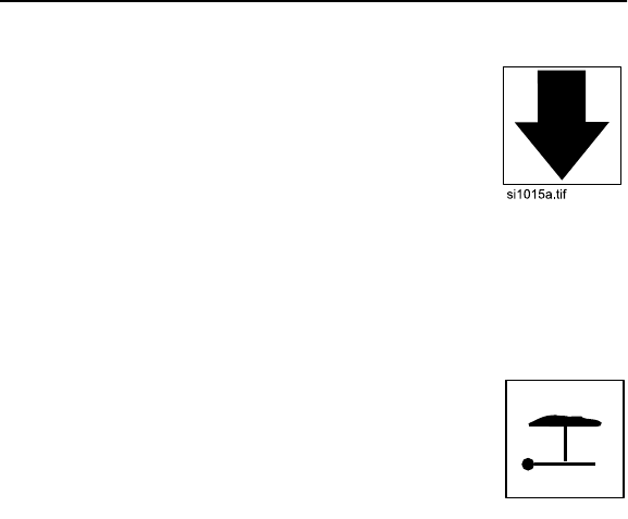
Down Arrow
•Press to decrease manual gain (decrease
signal) incrementally from 75 to 0.
•Press and hold to decrease manual gain
(decrease signal) more quickly.
•If signal is above 75, press once to
decrease gain (decrease signal) to
approximately 50.
Depth
•Press once to estimate depth of properly
located signal source.
IMPORTANT: See OPERATION for
information on locating signals.
•Press and hold while pressing another button to enable 2nd
function of that button. 2nd functions are described on the
following page.
si0007h.eps
10 300SR/ST - RECEIVER
2ND FUNCTION CONTROLS 10 300SR/ST - RECEIVER
2ND FUNCTION CONTROLS
2ND FUNCTION CONTROLS
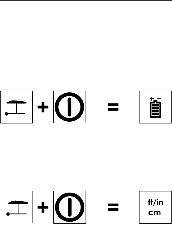
To use these functions, press and hold the first button indicated,
then press the second button.
Battery Life
Shows percent of battery life remaining.
Units of Measurement
Changes the units of measurement in which the depth is
displayed. Available displays are ft/in or cm/m.
IMPORTANT: Press this key sequence with the unit off.
c00ic098h.eps
c00ic102h.eps
2ND FUNCTION CONTROLS
To use these functions, press and hold the first button indicated,
then press the second button.
Battery Life
Shows percent of battery life remaining.
Units of Measurement
Changes the units of measurement in which the depth is
displayed. Available displays are ft/in or cm/m.
IMPORTANT: Press this key sequence with the unit off.
c00ic098h.eps
c00ic102h.eps
300SR/ST - RECEIVER 11
2ND FUNCTION CONTROLS
300SR/ST - RECEIVER 11
2ND FUNCTION CONTROLS
Frequency
Selects frequency mode: power (60 Hz or 50 Hz), radio, or active
(8 kHz or 29 kHz).
Volume
Turns volume on or off.
Backlight
Turns backlight on or off.
c00ic099h.eps
c00ic100h.eps
c00ic101h.eps
Frequency
Selects frequency mode: power (60 Hz or 50 Hz), radio, or active
(8 kHz or 29 kHz).
Volume
Turns volume on or off.
Backlight
Turns backlight on or off.
c00ic099h.eps
c00ic100h.eps
c00ic101h.eps
12 300SR/ST - RECEIVER
DISPLAY 12 300SR/ST - RECEIVER
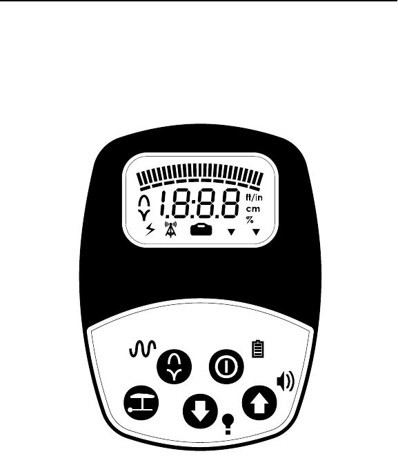
DISPLAY
DISPLAY
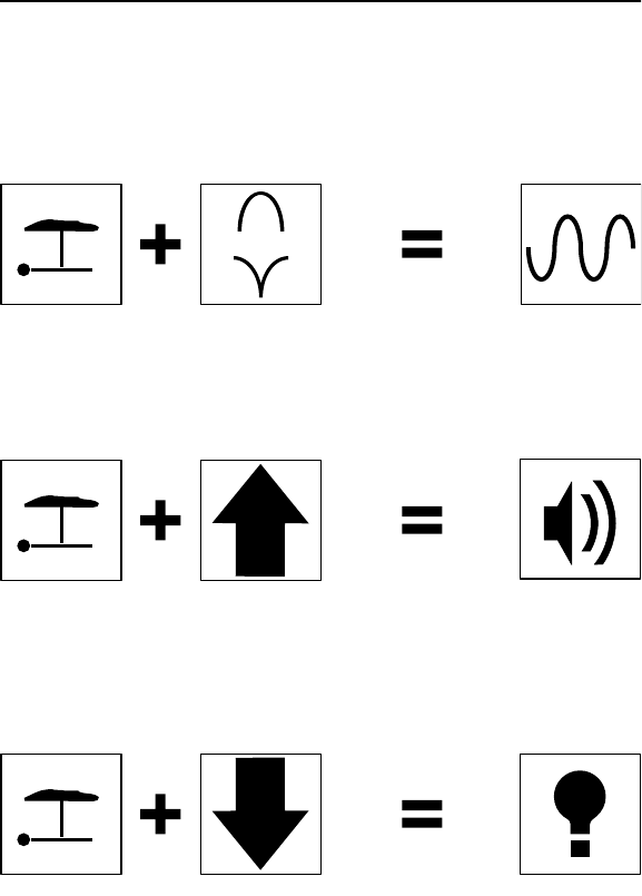
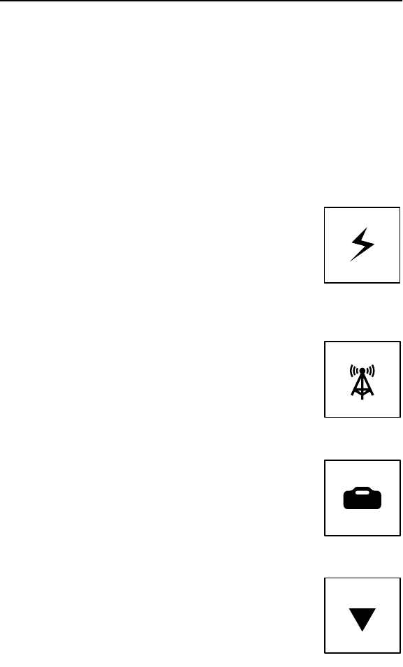
Mode
The receiver can be configured to operate in four modes
described below. The icon for the currently selected mode is
shown along the bottom of the display.
Power
Allows receiver to trace live 50 Hz or 60 Hz
power lines.
IMPORTANT: Current must be flowing through
the line.
Radio
Allows receiver to trace lines that pick up and
radiate very low frequency (VLF) radio waves.
Transmitter
Allows receiver to trace lines that have had a
29 kHz or 8 kHz signal placed on them by a
transmitter.
Beacon
This optional mode allows receiver to trace
nonmetallic pipes and conduits with 29 kHz
beacon.
si0008h.eps
si0009h.eps
si0010h.eps
si0011h.eps
DISPLAY
Mode
The receiver can be configured to operate in four modes
described below. The icon for the currently selected mode is
shown along the bottom of the display.
Power
Allows receiver to trace live 50 Hz or 60 Hz
power lines.
IMPORTANT: Current must be flowing through
the line.
Radio
Allows receiver to trace lines that pick up and
radiate very low frequency (VLF) radio waves.
Transmitter
Allows receiver to trace lines that have had a
29 kHz or 8 kHz signal placed on them by a
transmitter.
Beacon
This optional mode allows receiver to trace
nonmetallic pipes and conduits with 29 kHz
beacon.
si0008h.eps
si0009h.eps
si0010h.eps
si0011h.eps
300SR/ST - RECEIVER 13
DISPLAY
300SR/ST - RECEIVER 13
DISPLAY
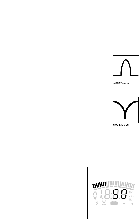
Antenna
The receiver has two antenna modes described below. The icon
for the currently selected mode is shown on the left side of the
display.
Peak
Signal strength peaks when receiver is over
the line being located.
Null
Signal drops to minimum strength when
receiver is over the line being located. Gives a
more precise response when locating lines in
uncongested areas.
IMPORTANT: In congested areas, confirm
location by using peak antenna.
Signal Strength
Signal strength is shown by bars
at top of display and in numeric
display.
ss1122h.eps
14 300SR/ST - RECEIVER
DISPLAY 14 300SR/ST - RECEIVER
DISPLAY
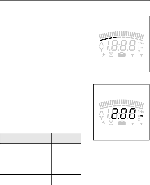
Gain
Gain (amount of signal
amplification) is shown by bars
below signal strength indicator.
Gain increases to the right.
Depth
Estimated depth displays when
depth button is pressed.
Receiver can display depth the
following ways:
IMPORTANT: If three dashes or three dots appear in the display,
the receiver is experiencing an error. See CARE AND ERROR
CODES.
Depth Display
up to 47 in inches
48 in and deeper feet/inches
up to 99 cm cm
100 cm and deeper meters
ss1123h.eps
ss1124h.eps
300SR/ST - RECEIVER 15
SETUP
300SR/ST - RECEIVER 15
SETUP
SETUP
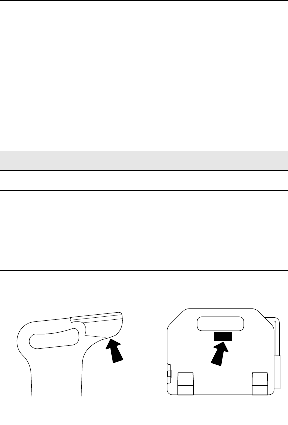
Install Batteries
Use six C-cell alkaline batteries in
receiver.
To install:
1. Unscrew battery cover.
2. Insert batteries as shown.
3. Close and tighten battery
cover.
4. Check operation.
Check Operation
Always check that receiver is
operating before leaving for jobsite
and after every battery change.
To check operation:
1. Turn on receiver.
2. Entire display will light briefly.
3. Display will show last used
setting.
ss1134h.eps
ss1126h.eps
SETUP
Install Batteries
Use six C-cell alkaline batteries in
receiver.
To install:
1. Unscrew battery cover.
2. Insert batteries as shown.
3. Close and tighten battery
cover.
4. Check operation.
Check Operation
Always check that receiver is
operating before leaving for jobsite
and after every battery change.
To check operation:
1. Turn on receiver.
2. Entire display will light briefly.
3. Display will show last used
setting.
ss1134h.eps
ss1126h.eps

16 300SR/ST - RECEIVER 16 300SR/ST - RECEIVER
300SR/ST - TRANSMITTER 17
OVERVIEW
300SR/ST - TRANSMITTER 17
OVERVIEW
TRANSMITTER
OVERVIEW
The Ditch Witch Subsite 300ST transmitter is designed to place
signals on target lines. It can be configured to send 8 kHz or 29
kHz frequencies. It places a signal on the line through either
direct connection, induction clamping, or broadcast modes.
ss1130h.eps
POWER
OUTPUT
ON/
OFF
18 300SR/ST - TRANSMITTER
CONTROLS AND INDICATORS 18 300SR/ST - TRANSMITTER
CONTROLS AND INDICATORS
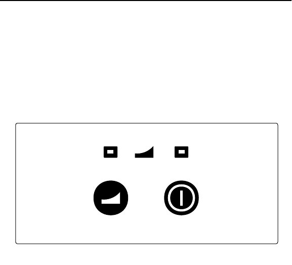
CONTROLS AND INDICATORS
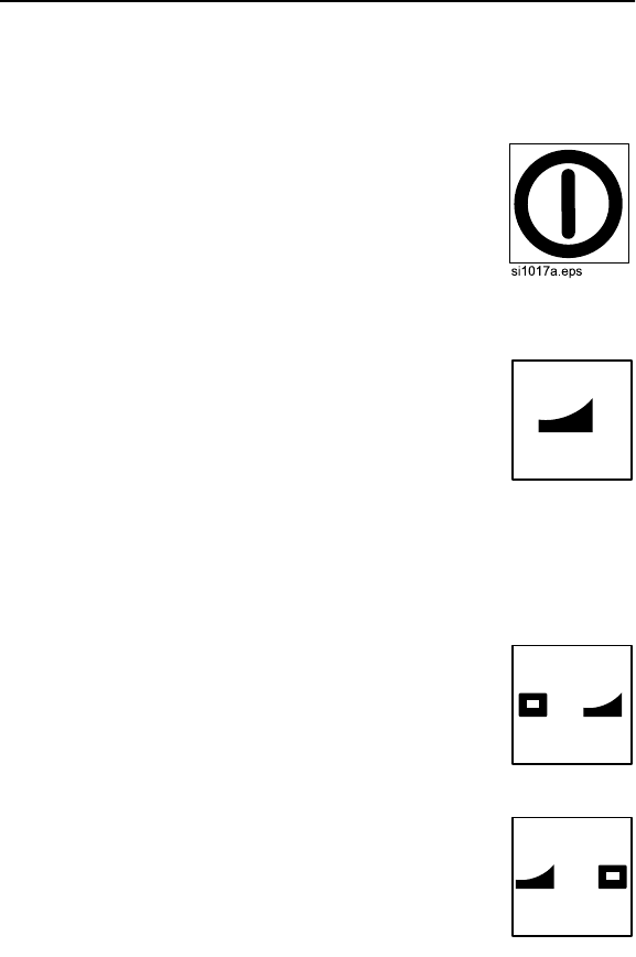
ON/OFF Button
Turns unit on and off.
•Press once to turn on.
•Press again to turn off.
POWER OUTPUT Button
Selects low or high power output.
•On power up, the 300ST defaults to low
power output.
•Press once to change to high.
•Press again to change to low.
Power Output LEDs
Display which power output is currently
functioning.
•Green LED indicates low power.
•Red LED indicates high power.
si0012h.eps
si0013h.eps
si0014h.eps
CONTROLS AND INDICATORS
ON/OFF Button
Turns unit on and off.
•Press once to turn on.
•Press again to turn off.
POWER OUTPUT Button
Selects low or high power output.
•On power up, the 300ST defaults to low
power output.
•Press once to change to high.
•Press again to change to low.
Power Output LEDs
Display which power output is currently
functioning.
•Green LED indicates low power.
•Red LED indicates high power.
si0012h.eps
si0013h.eps
si0014h.eps

300SR/ST - TRANSMITTER 19
SETUP
300SR/ST - TRANSMITTER 19
SETUP
SETUP
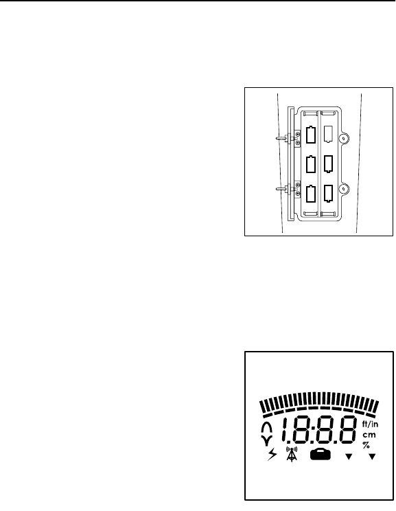
Install Batteries
Use six D-cell alkaline batteries in
transmitter.
To install:
1. Unscrew battery cover.
2. Insert batteries as shown.
3. Close and tighten battery
cover.
4. Check operation.
Check Operation
Always check that transmitter is operating before leaving for
jobsite and after every battery change.
To check operation:
1. Turn on transmitter.
2. Transmitter will beep and green LED will light.
NOTICE: If both LEDs flash and transmitter beeps repeatedly,
batteries are low.
ss1135h.eps
SETUP
Install Batteries
Use six D-cell alkaline batteries in
transmitter.
To install:
1. Unscrew battery cover.
2. Insert batteries as shown.
3. Close and tighten battery
cover.
4. Check operation.
Check Operation
Always check that transmitter is operating before leaving for
jobsite and after every battery change.
To check operation:
1. Turn on transmitter.
2. Transmitter will beep and green LED will light.
NOTICE: If both LEDs flash and transmitter beeps repeatedly,
batteries are low.
ss1135h.eps

20 300SR/ST - TRANSMITTER 20 300SR/ST - TRANSMITTER

300SR/ST - SAFETY 21
300SR/ST - SAFETY 21
SAFETY
Follow these guidelines before operating any jobsite equipment:
•Read and follow all safety precautions.
•Complete proper training and read operator’s manual before
using equipment.
•Use equipment only as directed.
•Contact One-Call (888-258-0808) and any utility companies
which do not subscribe to One-Call. Have all underground
pipes and cables located and marked before sweeping area.
•Classify jobsite based on its hazards and use correct tools
and machinery, safety equipment, and work methods for
jobsite.
•Wear personal protective equipment.
•Check that equipment is in good condition, and test leads are
clean and have no cracked insulation.
•Contact your Ditch Witch Subsite dealer if you have any
question about operation, maintenance, or equipment use.

22 300SR/ST - SAFETY
SAFETY ALERT CLASSIFICATIONS 22 300SR/ST - SAFETY
SAFETY ALERT CLASSIFICATIONS
SAFETY ALERT CLASSIFICATIONS
These classifications and the icons defined on the following
pages work together to alert you to situations which could be
harmful to you, jobsite bystanders or your equipment. When you
see these words and icons in the book or on the machine,
carefully read and follow all instructions. YOUR SAFETY IS AT
STAKE.
Watch for the three safety alert levels: DANGER, WARNING and
CAUTION. Learn what each level means.
indicates an imminently hazardous situation
which, if not avoided, will result in death or serious injury.
indicates a potentially hazardous situation which,
if not avoided, could result in death or serious injury.
indicates a potentially hazardous situation which,
if not avoided, may result in minor or moderate injury.
Watch for two other words: NOTICE and IMPORTANT.
NOTICE can keep you from doing something that might damage
the machine or someone’s property. It can also alert you against
unsafe practices.
IMPORTANT can help you do a better job or make your job
easier in some way.

300SR/ST - SAFETY 23
SAFETY ALERTS
300SR/ST - SAFETY 23
SAFETY ALERTS
SAFETY ALERTS
Incorrect procedures could result
in death, injury, or property damage. Learn to use
equipment correctly.
NOTICES:
•Electric shock or equipment damage can result if transmitter
is connected to live cable. Have qualified personnel
disconnect both ends of cable before working.
•Turn off transmitter when connecting or moving ground stake.
•If target depth and location are critical, confirm by hand-
digging.
Jobsite hazards
could cause death or serious injury.
Use correct equipment and work
methods. Use and maintain proper
safety equipment.
Moving traffic - hazardous
situation. Death or serious injury could result.
Avoid moving vehicles, wear high visibility clothing,
post appropriate warning signs.

24 300SR/ST - SAFETY
SAFETY ALERTS 24 300SR/ST - SAFETY
SAFETY ALERTS

300SR/ST - OPERATION 25
CHOOSE SIGNAL TYPE
300SR/ST - OPERATION 25
CHOOSE SIGNAL TYPE
OPERATION
CHOOSE SIGNAL TYPE
The 300SR can detect two types of signals:
•Active signals are placed on a target line with the transmitter
and detected by the receiver. As an option, an active signal
from a beacon can also be detected by the receiver.
•Passive signals reside on the target line and are read by
receiver.
Read the descriptions on the next page and determine the signal
type to use for your job.

26 300SR/ST - OPERATION
CHOOSE SIGNAL TYPE 26 300SR/ST - OPERATION
CHOOSE SIGNAL TYPE
Active
There are three ways to place active signals on a target line with
a transmitter:
•Direct connection (preferred method) requires a connection
to be made directly onto target line.
•Induction clamp requires placing an optional induction clamp
around target line.
•Broadcast method requires no connection and sends current
into lines near the transmitter.
Beacon
If equipped, trace non-metallic pipes or conduits by locating and
following a 29 kHz beacon signal.
Passive
Some utility lines pick up signals from the environment and carry
them as detectable signals. These passive signals can be power
signals or radio signals.
IMPORTANT: No depth estimates are available in this mode.

300SR/ST - OPERATION 27
CHOOSE ANTENNA CONFIGURATION
300SR/ST - OPERATION 27
CHOOSE ANTENNA CONFIGURATION
CHOOSE ANTENNA CONFIGURATION
The 300SR receiver has two antenna configurations:
CHOOSE FREQUENCY
Receiver
Set the 300SR receiver to one of the following frequencies:
•power (50 Hz or 60 Hz)
•radio
•active (8 kHz or 29 kHz)
Transmitter
Your 300ST transmitter was configured at the time of purchase to
send either 8 kHz or 29 kHz signals.
Antenna Description When to use
peak Uses two horizontal
antenna to detect signal.
Response is highest at
strongest signal.
This is the preferred
configuration for most
applications.
null Uses a vertical antenna to
detect signal. Response is
lowest when receiver is
over the line.
Use primarily to verify
the location of a target
line after it has been
located with the peak
antenna.

28 300SR/ST - OPERATION
RECOGNIZE COMMON SIGNAL PROBLEMS 28 300SR/ST - OPERATION
RECOGNIZE COMMON SIGNAL PROBLEMS
RECOGNIZE COMMON SIGNAL PROBLEMS
Distortions in the electromagnetic field around a line can affect
location and depth accuracy. Tees, bends, parallel lines, crossing
lines, or large metallic objects can distort signals.
NOTICE: If target depth and location are critical, confirm by hand-
digging or vacuum excavation.
Learn to recognize the following kinds of distortion:
Shadows
Shadows, also called blind spots, often happen when a metallic
object partially obstructs signal, or a signal from a parallel line
interferes with target signal.
False Signals
False signals describe situations where the receiver indicates a
line location where there is no line. False signals often happen
when a line tees or bends, runs parallel to the target line, or
crosses the target line.
IMPORTANT: Generally, the receiver shows less distortion in peak
antenna configuration.
300SR/ST - OPERATION 29
RECOGNIZE COMMON SIGNAL PROBLEMS
300SR/ST - OPERATION 29
RECOGNIZE COMMON SIGNAL PROBLEMS
Secondary (Ghost) Signals
A typical beacon signal pattern shows a main signal and two
weaker secondary signals. Identify beacon location at the main
signal. Familiarity with beacon signal patterns will lessen the
effect of ghost signals.
ss1138h.eps
Secondary (Ghost) Signals
A typical beacon signal pattern shows a main signal and two
weaker secondary signals. Identify beacon location at the main
signal. Familiarity with beacon signal patterns will lessen the
effect of ghost signals.
ss1138h.eps

30 300SR/ST - OPERATION
LOCATE LINE: ACTIVE LOCATION 30 300SR/ST - OPERATION
LOCATE LINE: ACTIVE LOCATION
LOCATE LINE: ACTIVE LOCATION
Setup
Follow setup procedures for the type of locating you will be doing:
direct connection, induction clamp, or broadcast induction.
Direct Connection
Jobsite hazards
could cause death or serious injury.
Use correct equipment and work
methods. Use and maintain proper
safety equipment.
NOTICE: Electric shock or equipment damage can result if
transmitter is connected to live cable. Contact qualified utility
personnel and follow all local standards and restrictions for
disconnecting and grounding lines.
To set up transmitter for direct connection:
1. Drive ground stake.
2. Plug cable into transmitter.
3. Hook black cable to ground stake.
4. Hook clip to line.
5. Turn on transmitter.
NOTICE: Turn off transmitter when connecting or moving ground
300SR/ST - OPERATION 31
LOCATE LINE: ACTIVE LOCATION
300SR/ST - OPERATION 31
LOCATE LINE: ACTIVE LOCATION
stake.stake.
32 300SR/ST - OPERATION
LOCATE LINE: ACTIVE LOCATION 32 300SR/ST - OPERATION
LOCATE LINE: ACTIVE LOCATION
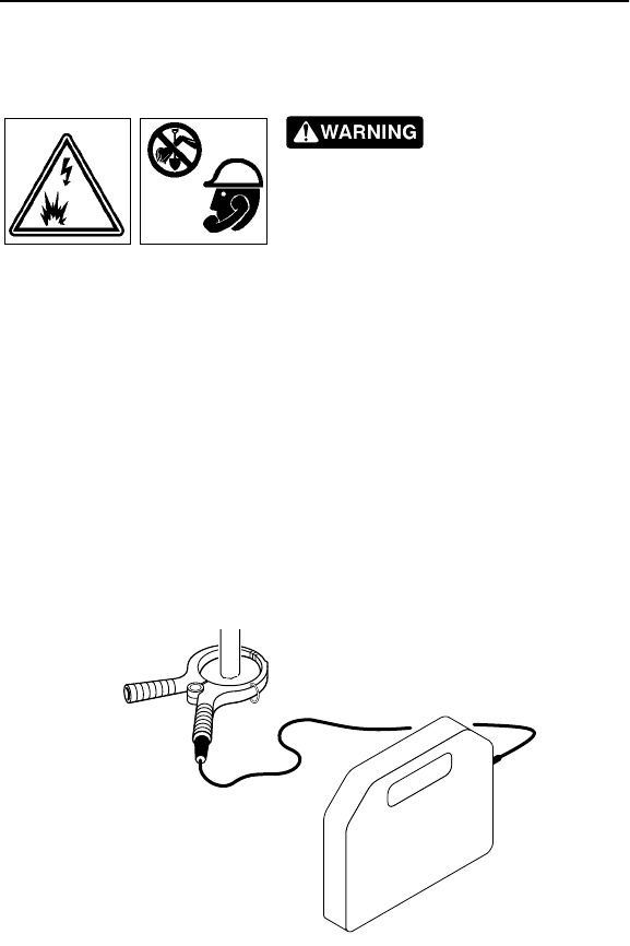
Induction Clamp
Jobsite hazards
could cause death or serious injury.
Use correct equipment and work
methods. Use and maintain proper
safety equipment.
NOTICE: Electric shock or equipment damage can result if
transmitter is connected to live cable. Contact qualified utility
personnel and follow all local standards and restrictions for
disconnecting and grounding lines.
To set up transmitter for use with induction clamp:
1. Plug cable into transmitter.
2. Place clamp around target line.
3. Turn on transmitter.
1137h.eps
300SR/ST - OPERATION 33
LOCATE LINE: ACTIVE LOCATION
300SR/ST - OPERATION 33
LOCATE LINE: ACTIVE LOCATION
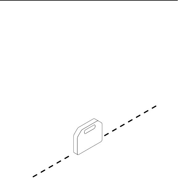
Broadcast Induction
To set up transmitter for broadcast induction:
1. Remove cable, stake, clamp and any other metal objects
from transmitter.
2. Place transmitter in line with suspected line.
3. Turn on transmitter.
1136h.eps
Broadcast Induction
To set up transmitter for broadcast induction:
1. Remove cable, stake, clamp and any other metal objects
from transmitter.
2. Place transmitter in line with suspected line.
3. Turn on transmitter.
1136h.eps
34 300SR/ST - OPERATION
LOCATE LINE: ACTIVE LOCATION 34 300SR/ST - OPERATION
LOCATE LINE: ACTIVE LOCATION
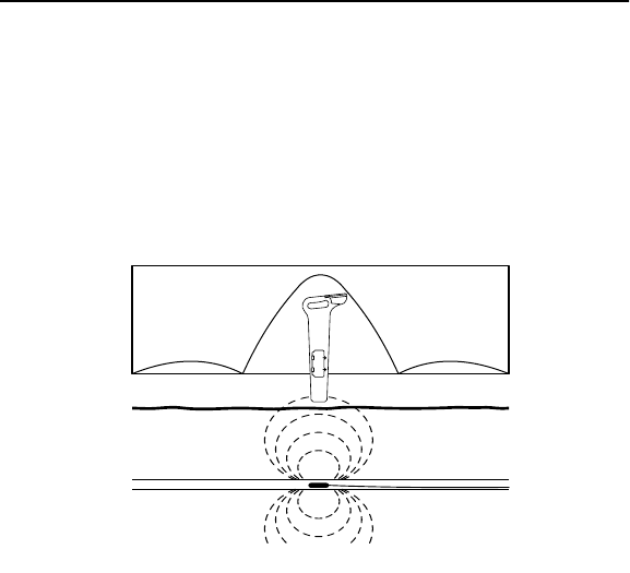
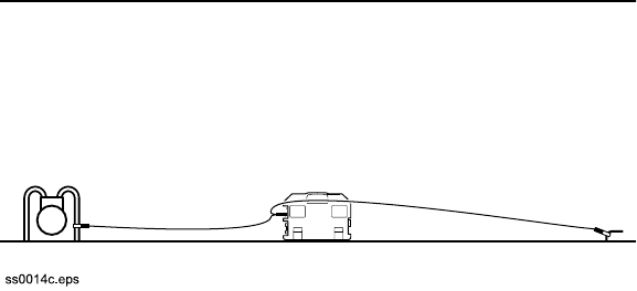
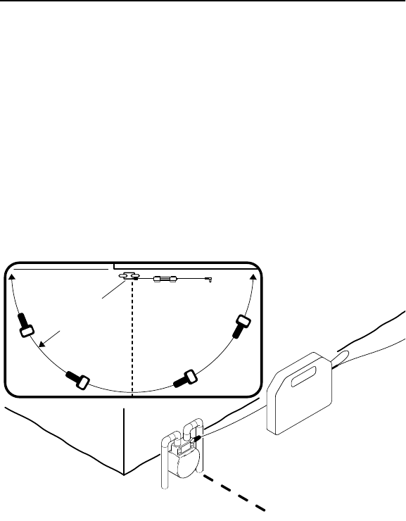
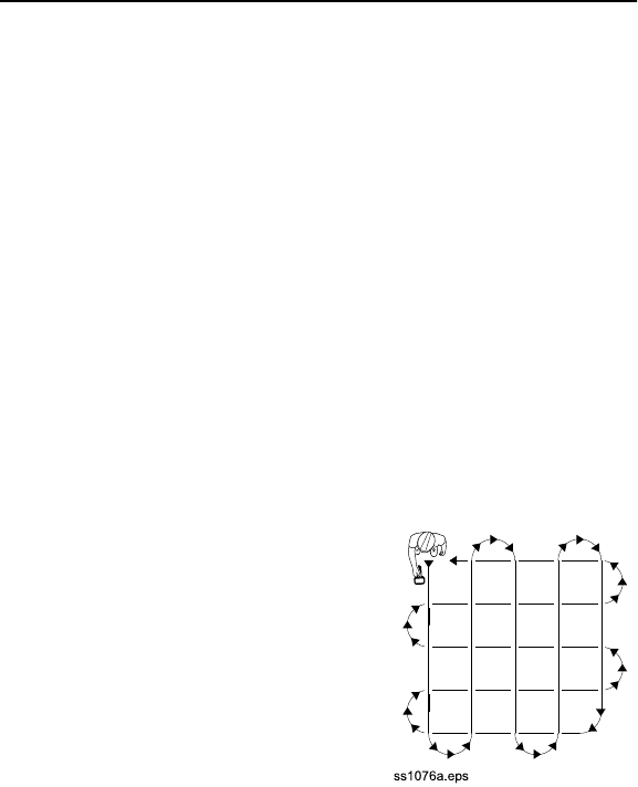
Technique
IMPORTANT: Follow steps 1-3 for all types of active location. For
reference, the illustration below shows direct connection method.
If using broadcast induction, ensure that transmitter is in line with
and above suspected line, as shown on previous page.
1. Walk in an arc approximately 25 ft (7.5 m) around transmitter.
2. Hold the receiver as shown.
3. Identify location of line by finding the spot with the strongest
signal response.
ss1131h.eps
7.5 m
25 ft

300SR/ST - OPERATION 35
LOCATE LINE: ACTIVE LOCATION
300SR/ST - OPERATION 35
LOCATE LINE: ACTIVE LOCATION
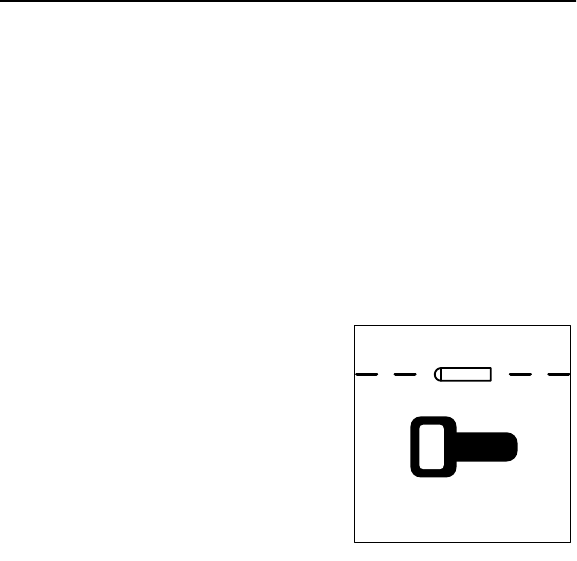
4. Rotate the receiver to
determine which direction the
line runs.
IMPORTANT: Receiver
indicates the strongest signal
when the handle is
perpendicular to the target
line.
5. Set the receiver on the
ground.
6. Press depth button when the line has been located.
IMPORTANT: When estimating depth for pipe, depth shown
is to the center of the pipe.
7. Continue to trace the line and take depth estimates every few
paces.
8. Retrace the line and mark with appropriate flags or paint.
ss1132.eps

36 300SR/ST - OPERATION
LOCATE LINE: ACTIVE LOCATION 36 300SR/ST - OPERATION
LOCATE LINE: ACTIVE LOCATION
Special Situations
Situation What to try
Signal is lost. Walk in a circle to detect a tee or
bend in the line.
Signal varies from low to
high and is unstable. Mark as a hand-dig area.
You are near a power line
and are receiving
interference such as
unstable depth readings,
blank display, etc.
Sweep the area in power mode. If
receiver gives a strong signal
response, a power line is
interfering with transmitter signal.
Receiver does not function
properly. Receiver gain could be set too
high or low. Lower or raise gain to
locate the line. Also ensure that
receiver is set to the correct mode.
Target line has
connections to other lines. Disconnect target line from other
lines.
Signal is transferring to
other lines. •Lower the power level.
•Use direct connection, if
possible, or use induction
clamp.
•Move the ground stake away
from the target line and away
from other buried lines.
•Apply signal at the point where
the target line is farthest from
the other lines.
Three dashes appear on
the display. See CARE AND ERROR CODES.

300SR/ST - OPERATION 37
LOCATE: BEACON
300SR/ST - OPERATION 37
LOCATE: BEACON
LOCATE: BEACON
If equipped, trace non-metallic pipes or conduits by locating and
following a 29 kHz beacon signal.
IMPORTANT: Large metal objects and other signals (such as
railroad signals or overhead power lines) can distort signal.
Setup
To set up for beacon location:
1. Follow beacon manufacturer’s instructions on battery
installation and testing beacon operation.
2. Attach beacon to plumber’s snake or flex rod.
38 300SR/ST - OPERATION
LOCATE: BEACON 38 300SR/ST - OPERATION
LOCATE: BEACON
Technique
1. Turn on receiver.
2. Set antenna to peak. Set frequency to beacon mode.
3. Place the beacon into the pipe and move it down the pipe.
4. To locate the beacon, circle over its approximate location in
the pipe.
5. To identify the location of beacon, find the spot with the
strongest signal response.
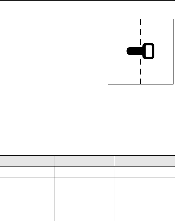
6. Rotate the receiver to
determine which direction the
beacon runs.
IMPORTANT: Receiver
indicates the strongest signal
when handle is parallel with
and directly over the beacon.
7. Press the depth button.
NOTICE: When estimating
depth with a beacon in
nonmetallic pipe, depth shown will be to the center of the
beacon, not to the top of the pipe.
8. Continue to track the beacon and take depth readings. Mark
pipe location with paint.
ss1133h.eps
Technique
1. Turn on receiver.
2. Set antenna to peak. Set frequency to beacon mode.
3. Place the beacon into the pipe and move it down the pipe.
4. To locate the beacon, circle over its approximate location in
the pipe.
5. To identify the location of beacon, find the spot with the
strongest signal response.
6. Rotate the receiver to
determine which direction the
beacon runs.
IMPORTANT: Receiver
indicates the strongest signal
when handle is parallel with
and directly over the beacon.
7. Press the depth button.
NOTICE: When estimating
depth with a beacon in
nonmetallic pipe, depth shown will be to the center of the
beacon, not to the top of the pipe.
8. Continue to track the beacon and take depth readings. Mark
pipe location with paint.
ss1133h.eps

300SR/ST - OPERATION 39
LOCATE LINE: PASSIVE LOCATION
300SR/ST - OPERATION 39
LOCATE LINE: PASSIVE LOCATION
LOCATE LINE: PASSIVE LOCATION
Setup
To set up for passive location, turn on receiver. Choose the power
or radio frequency, and select the best antenna configuration for
your job. See “Choose Antenna Configuration” earlier in this
chapter.
Always check receiver battery level at startup.
Electric shock. Contacting electric
lines will cause death or serious injury. Know
location of lines and stay away.
NOTICE: Lines with no AC current flowing through them are hard
to detect and dangerous because they still have voltage. To locate,
turn on an appliance to cause current flow and use power mode,
or use active or radio search methods. Do not use direct connect.
40 300SR/ST - OPERATION
LOCATE LINE: PASSIVE LOCATION 40 300SR/ST - OPERATION
LOCATE LINE: PASSIVE LOCATION
Technique
Survey the Site
Make a visual check of the site for signs of buried lines such as:
•recent trenching
•buried line markers
•overhead lines that run down poles and underground
•gas meters
•valve sights
•drains or manhole covers
Sweep the Site
Search the site by walking a grid
pattern while holding receiver
close to the ground.
IMPORTANT: Keep the receiver
vertical.
Focus the Signal
Move the receiver over the detected signal to find the strongest
signal response. If using peak antenna mode, rotate the receiver
until the signal is strongest. Strongest signal indicates line
direction.
300SR/ST - OPERATION 41
LOCATE LINE: PASSIVE LOCATION
300SR/ST - OPERATION 41
LOCATE LINE: PASSIVE LOCATION
Trace the Line
Walk along the suspected path
while moving the receiver back
and forth across the area.
IMPORTANT: Keep receiver
handle perpendicular to the
suspected line path.
Mark the Line
Sweep, focus, and trace all detected signals in the area. Mark
line paths with colored paint or flags. See the chart below for
standard color markings for line locations or check local
regulations.
Utility Color Marking Symbol
electric red -E-
gas/oil yellow -G-
communications orange -TEL- or -TV-
water blue -W-
sewer green -S-
ss1132.eps

42 300SR/ST - OPERATION
LOCATE LINE: PASSIVE LOCATION 42 300SR/ST - OPERATION
LOCATE LINE: PASSIVE LOCATION
Special Situations
Situation What to try
Signal is lost. Walk in a circle to detect a tee or
bend in the line.
Signal varies from low to
high and is unstable. Check the transmitter connection.
If connection is good and signal is
still unstable, mark as a hand-dig
area.
Receiver does not function
properly. Receiver gain could be set too
high or low. Lower or raise gain to
locate the line.
Three dashes appear on
the display when depth
button is pressed.
See CARE AND ERROR CODES.

300SR/ST - OPERATION 43
FCC Statement -- Internal Transmitter
300SR/ST - OPERATION 43
FCC Statement -- Internal Transmitter
FCC Statement -- Internal Transmitter
This equipment has been tested and found to comply with the
limits for a Class B device, pursuant to Part 15 of the FCC rules.
These limits are designed to provide reasonable protection
against harmful interference in a residential installation. This
equipment generates, uses and can radiate radio frequency
energy and, if not installed and used in accordance with the
instructions, may cause harmful interference to radio
communications. However, there is no guarantee that
interference will not occur in a particular installation. If this
equipment does cause harmful interference to radio or television
reception, which can be determined by turning the equipment off
and on, the user is encouraged to try to correct the interference
by one or more of the following measures:
•Reorient or relocate the receiving antenna.
•Increase the separation between equipment and receiver.
•Consult the dealer or an experienced radio/TV technician for
help.
Section 15.19 (a) (1) states: “Receivers associated with the
operation of a licensed radio service, e.g. FM broadcast under
Part 73 of this chapter, land mobile operation under Part 90, etc.,
shall bear the following statement in a conspicuous location on
the device: This device complies with Part 15 of the FCC rules.
Operation is subject to the condition that this device does not
cause harmful interference.”
Changes or modifications not expressly approved in writing by
The Charles Machine Works, Inc. may void the user’s authority
to operate this equipment.

44 300SR/ST - OPERATION
FCC Statement -- Internal Transmitter 44 300SR/ST - OPERATION
FCC Statement -- Internal Transmitter

300SR/ST - CARE AND ERROR CODES 45
GENERAL CARE
300SR/ST - CARE AND ERROR CODES 45
GENERAL CARE
CARE AND ERROR CODES
Under normal operating conditions, receiver needs only minor
maintenance. Following these care instructions can ensure
longer equipment life.
GENERAL CARE
•Do not drop the equipment.
•Do not expose the equipment to high heat (such as in the rear
window of a car).
•Clean equipment with a damp cloth and mild soap. Never use
scouring powder.
•Do not immerse in any liquid.
•Inspect housing daily for cracks or other damage. If housing is
damaged, contact your Ditch Witch Subsite dealer for
replacement.
46 300SR/ST - CARE AND ERROR CODES
ERROR CODES 46 300SR/ST - CARE AND ERROR CODES
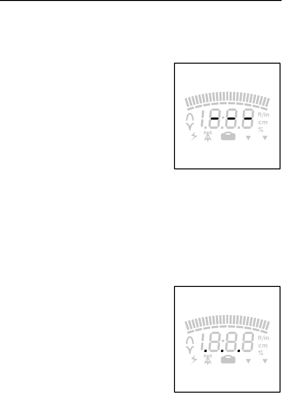
ERROR CODES
ERROR CODES
If three dashes appear in the
display when pressing the depth
button, one of the following could
be possible:
•The receiver is detecting a
signal above it and cannot
estimate depth. This message
is usually caused by interfering
signals. Try relocating target
signal.
•Line is too deep for depth
estimate. Mark as a hand-dig area.
•Line is too shallow for depth estimate. Select lowest usable
transmitter power level or lift receiver high enough to return
display to normal operation. Relocate line and verify with null
antenna.
If three dots appear in the display
when pressing the depth button,
contact your Ditch Witch Subsite
dealer.
ss1125h.eps
ss1139h.eps
300SR/ST - SPECIFICATIONS 47
300 RECEIVER
300SR/ST - SPECIFICATIONS 47
300 RECEIVER
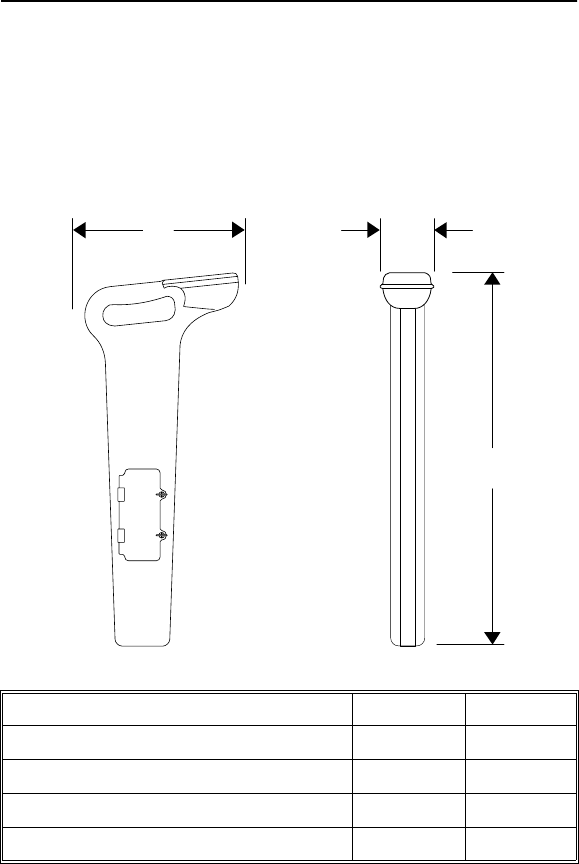
SPECIFICATIONS
300 RECEIVER
Dimensions U.S. Metric
Length 11.5 in 700 mm
Width 4.0 in 100 mm
Height 27.5 in 290 mm
Operating weight 5.0 lb 2.3 kg
L
H
W
SPECIFICATIONS
300 RECEIVER
Dimensions U.S. Metric
Length 11.5 in 700 mm
Width 4.0 in 100 mm
Height 27.5 in 290 mm
Operating weight 5.0 lb 2.3 kg
L
H
W

48 300SR/ST - SPECIFICATIONS
300 RECEIVER 48 300SR/ST - SPECIFICATIONS
300 RECEIVER
Operation U.S. Metric
Operating temperature range -4°F to
122°F-20°C to
50°C
Antenna configurations peak, null
Audio output speaker
Operating modes
Active line: 8 kHz or 29 kHz
Beacon (locate/depth only): 29 kHz option only
Passive line: 50 Hz or 60 Hz, no depth available
Radio: passive locate only, no depth available
Locating ranges
Lines 15 ft 4.6 m
Beacons 10 ft 3 m
Maximum depth ranges**
Active line ±5% .5 - 10 ft .15 - 3 m
Active line ±10% 10 ft and
deeper 3 m and
deeper
Beacon ±5% .5 - 10 ft .15 - 3 m
LCD backlight LED (green)
**Locators are calibrated to these tolerances under ideal test field conditions.
Actual operating field conditions may have signal distortions or may contain
noise sources which result in depth estimate accuracy that is less than specified.

300SR/ST - SPECIFICATIONS 49
300 RECEIVER
300SR/ST - SPECIFICATIONS 49
300 RECEIVER
Batteries
Batteries 6 C-cell alkaline
Battery life (continuous use at 70°F [21°C]) approximately 40 hours
Battery saver unit shuts off after 5
minutes of inactivity
Batteries
Batteries 6 C-cell alkaline
Battery life (continuous use at 70°F [21°C]) approximately 40 hours
Battery saver unit shuts off after 5
minutes of inactivity
50 300SR/ST - SPECIFICATIONS
300 TRANSMITTER 50 300SR/ST - SPECIFICATIONS
300 TRANSMITTER
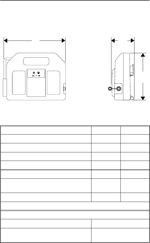
300 TRANSMITTER
Dimensions U.S. Metric
Length 12.25 in 311 mm
Width 4.5 in 114 mm
Height 9.25 in 235 mm
Operating weight 5.0 lb 2.3 kg
Operation U.S. Metric
Operating temperature range -4°F to
122°F-20°C to
50°C
Maximum power output 1 watt 1 watt
Operating modes: 8 kHz or 29 kHz
Batteries
Batteries 6 D-cell alkaline
Battery life (continuous use at low power
level) approximately 150 hours
ss1128h.eps
L
H
W
300
TRANSMITTER
POWER
OUTPUT
ON/
OFF

300SR/ST - WARRANTY 51
300SR/ST - WARRANTY 51
WARRANTY
Ditch Witch Subsite Electronics
Limited Product Warranty Policy
Warranty Periods
New Product
A twelve-month period starts on the date of delivery to the end user:
A six-month period starts on the date of delivery to the end user:
Beacons: 11B, 86B, 86BH, 86BHL, SBRP, 822B, 822BH, 910B
A three-month period starts on the date of delivery to the end user:
Beacons: BI
Accessories: cables, clamps, canoes, and adapters
Used Product (Cosmetics)
A three-month warranty starts on the date of delivery to the end user. (Non-
returnable) All used products have an RS added after the serial number.
Service and Repair
A one-month warranty on labor starts on the date the unit is repaired, and a three-
month warranty on parts starts on the date the unit is repaired for all products.
Extended Warranty
The extended warranty may be purchased at the time the equipment is sold or
within thirty days of ownership. The extension is for an additional twenty-four
months, for a total coverage of thirty-six months.
Trackers: 750 Tracker Remote Displays: 750 Display
Transmitters: 300ST, 950T, 75T Receivers: 300SR, 950R, 75R, EML
Fault Finders: AF1, FT12

52 300SR/ST - WARRANTY 52 300SR/ST - WARRANTY
Details and Exclusions
•The warranty includes only Ditch Witch Subsite products and accessories that
are manufactured and distributed by Ditch Witch Subsite Electronics. The
warranty compensates on defects in material or workmanship.
•Defects will be determined through inspection by Ditch Witch Subsite
Electronics or authorized repair centers. Original purchaser must make the
defective item available for inspection within 30 days of the date the part fails.
•The warranty is limited to replacement of the defective part. The replacement
part may be new or remanufactured. Repair and removal of defective part and
installation will be at no charge when product or item is delivered to Ditch Witch
Subsite Electronics or an authorized repair center. The product or item will be
returned at no charge for return freight.
•The warranty periods do not represent the useful life of Ditch Witch Subsite
Electronics products and accessories.
•If Ditch Witch Subsite products are purchased for commercial purposes, as
defined by the commerical code, no warranties extend beyond the specific
terms set forth in this limited warranty. All other provisions of this limited
warranty apply, including duties imposed.
•Ditch Witch Subsite products have been tested to deliver acceptable
performance in most conditions.
•This limited warranty applies to the original purchaser only. Some states or
jurisdictions do not allow exclusion or limitation of incidental or consequential
damages, so above limitation may not apply. This limited warranty gives original
purchaser specific rights that vary from state to state or jurisdiction to
jurisdiction.
•The Ditch Witch Subsite Equipment Registration Form must be completed for
each serial numbered product and submitted to Ditch Witch Subsite
Electronics. The information on the form is used to establish the warranty period
start date.

300SR/ST - WARRANTY 53
300SR/ST - WARRANTY 53
•When the Ditch Witch Subsite Equipment Registration Form is not processed
and received by Ditch Witch Subsite Electronics, the Ditch Witch Subsite
shipping date is used to establish the warranty period start date.
•Product inspection and estimates may require that the unit be disassembled
and tested.
•Out-of-warranty inspection costs include labor accrued at the full labor rate plus
return freight.
•Approved out-of-warranty repair costs include parts, labor accrued at full labor
rate, plus return freight.
Revision D, March 2002

54 300SR/ST - WARRANTY 54 300SR/ST - WARRANTY

300SR/ST - 55
300SR/ST - 55