Checkpoint Systems AMBER Part 15 Anti-Pilferage Device User Manual Boulevard MONO 20110421
Checkpoint Systems Inc Part 15 Anti-Pilferage Device Boulevard MONO 20110421
User Manual

SIDEP
Page 1 of 19
Boulevard
BoulevardBoulevard
Boulevard
Mono
Mono Mono
Mono System
SystemSystem
System
Installation Manual
Installation ManualInstallation Manual
Installation Manual
Document Version Rev2.
Document Version Rev2.Document Version Rev2.
Document Version Rev2.6
66
6
PN: 7961668

SIDEP
Page 2 of 19
Transceiver MONO system Installation Manual
Document revision information
Rev Description Date Author
2.4 Released by Sidep Electronic 11/01/07 Sidep electronic Co., Ltd.
2.5 Updated by Shanghai R&D 05/07/10 Jean Long
2.6 Updated by Shanghai R&D 04/21/11 Cucumber Huang
Trademarks
Sidep is a registered trademark of Sidep, Inc. All rights reserved. Information in this document is
subject to change without notice.
Other products © or ® their respective manufacturers or copyright holders.
Companies, names and data used in examples herein are fictitious unless otherwise noted. No part of
the contents of this book may be reproduced or transmitted in any form or by any means without the
written permission of the publisher.
Copyright and Warranty Information
The information in this document is subject to change without notice.
Because of the changing nature of this product information presented in the Transceiver MONO system
Installation Manual, Sidep, Inc. is not liable for any omissions, misstatements, or other errors of
information.
The information presented in this document may not be copied, used or disclosed to others for the
purpose of procurement or manufacturing without the written permission of Sidep, Inc. This guide and
the products discussed in this guide are the exclusive property of Sidep Inc. Copyright laws of the
United States protect all information and products.
Copyright© 2010 Sidep, Inc. All rights reserved.

SIDEP
Page 3 of 19
Changes or modifications not expressly approved by the party responsible for
compliance could void the user’s authority to operate the equipment.
for Canada:
This device complies with Industry Canada licence-exempt RSS standard(s).
Operation is subject to the following two conditions: (1) this device may not cause
interference, and (2) this device must accept any interference, including interference
that may cause undesired operation of the device.
Le présent appareil est conforme aux CNR d'Industrie Canada applicables aux
appareils radio exempts de licence. L'exploitation est autorisée aux deux conditions
suivantes : (1) l'appareil ne doit pas produire de brouillage, et (2) l'utilisateur de
l'appareil doit accepter tout brouillage radioélectrique subi, même si le brouillage est
susceptible d'en compromettre le fonctionnement.

SIDEP
Page 4 of 19
Table of Contents
1. GENERAL INFORMATION 5
1.1 ANTENNA TYPES 5
1.2 BOARD INTRODUCTION 6
1.3 POWER SUPPLY 7
1.4 TEST RANGE 8
2. GENERAL INSTALLATION 9
2.1 IMPLEMENTING ANTENNAS 9
2.2 INTERFERENCE SOURCES 9
3. SELECTION OF FUNCTIONING MODES WITH DIP SWITCH 11
4. BASIC ADJUSTMENT PROCEDURE 12
4.1 SINGLE SYSTEM ADJUSTMENT 12
5. MULTIPLE SYSTEM SYNCHRONIZATION 13
5.1 EXTERNAL SYNCHRONIZATION MODE WITH CABLE (UP TO 25 SYSTEMS BY
230V 50HZ MAIN POWER OR UP TO 25 SYSTEMS 120V 60HZ MAIN POWER) 13
5.2 SUPPLY SYNCHRONIZATION MODE WITH (UP TO 4 SYSTEMS BY 230V 50HZ
MAIN POWER OR UP TO 4 SYSTEMS 120V 60HZ MAIN POWER) 13
5.3 DEACTIVATOR SYNCHRONISATION 13
6. TROUBLE SHOOTING 14
7. ADVANCED ADJUSTMENT OF SYSTEM PARAMETERS 15
7.1 LEDS DS11-18 15
8. CONNECTIONS FROM MONO BOARD TO ANTENNA 16
9. MECHANICAL INSTLLATION 17
SIDEP
Page 5 of 19
1.GENERAL INFORMATION
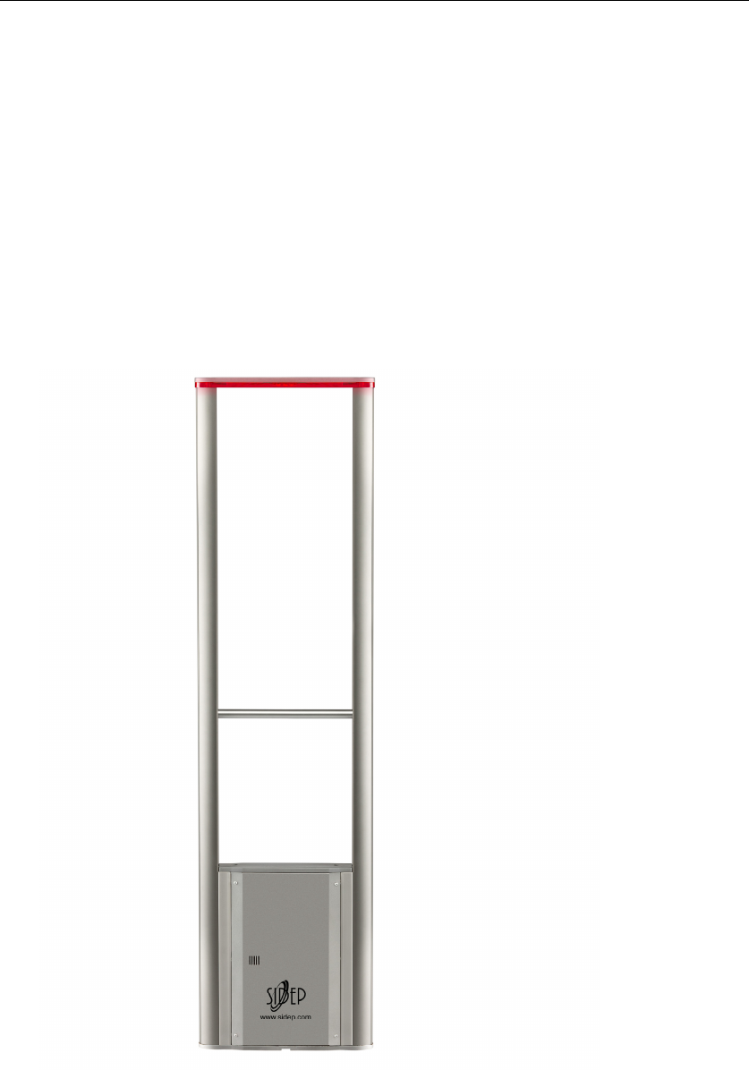
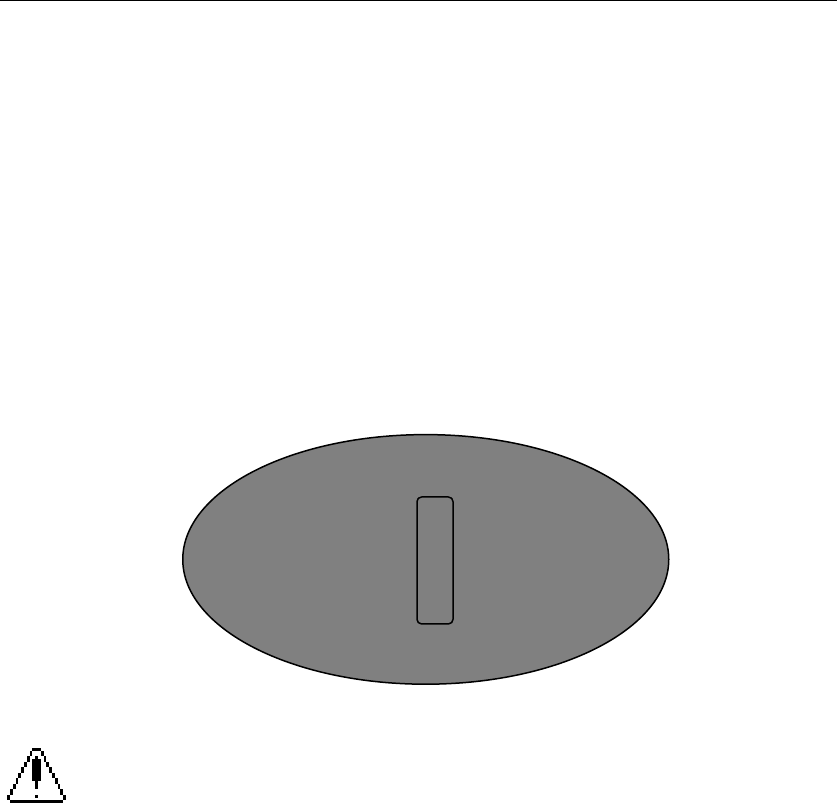
1.1 ANTENNA TYPES.
The installation manual is applied in boulevard antenna. The TX loop of
antenna is O-loop and the RX loop of antenna is 2-loop.
Figure 1.1
Boulevard Antenna
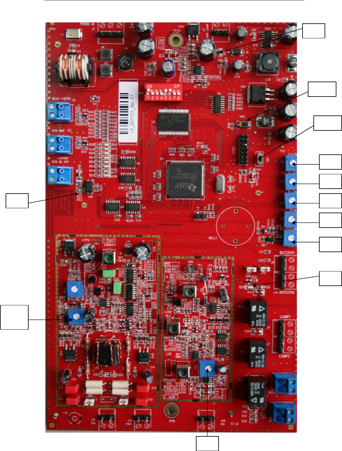
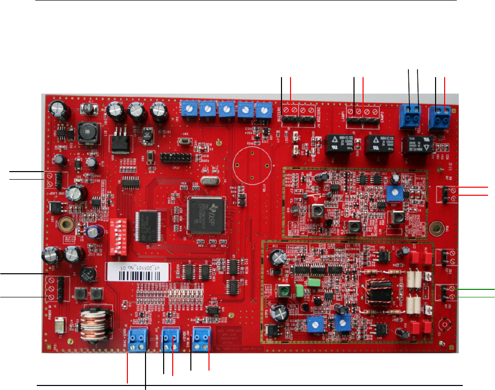
1.2 BOARD INTRODUCTION.
Figure 1.2
SIDEP
Page 6 of 19
SW1
DS3
DS2
VR5
SW2
VR4
VR3
VR2
VR1
VR6
DS1
TX
power
SIDEP
Page 7 of 19
SYN Trim:VR1
Synchronization
B-TMP Trim:VR2
Alarm sound time: long time in clockwise direction
B-MOD Trim: VR3
Buzzer frequency: low frequency in clockwise direction
L-TMP Trim:VR4
Alarm light time: long time in clockwise direction
RX GAIN Trim:VR5
Sensitivity: high sensitivity in clockwise direction
VOLUME Trim:VR6
Buzzer volume: low volume in clockwise direction
SW1
Reset system
SW2
Test function
DS1
Work display
DS2
Synchronization display
DS3
Alarm display
Firmware version : AMBER_FW_1.0
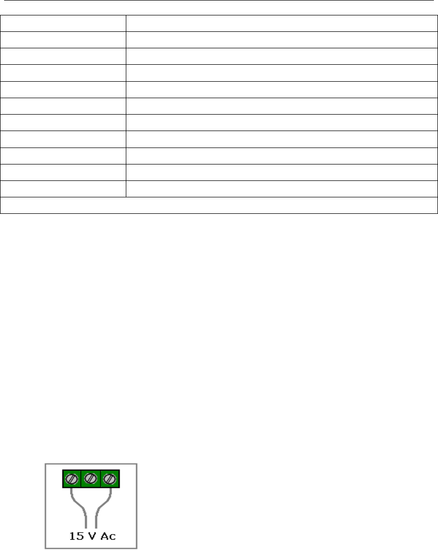
1.3 POWER SUPPLY
The basic system incorporates a transceiver Antenna, power supply adapter
(PSA). Both 230VAC 50Hz and 120VAC 60Hz main power can be used.
For 230VAC 50Hz main line, input power should be 150mA, and for 120VAC
60Hz main line, input power should be 250mA.
Make sure your anti theft system is connected to an electrical system
complying with the national regulations in force.
Recommended input power of MONO system is 15 VAC 800mA.
Only 1 antenna can be connected to the PSA provided.
Figure 1.3
Cabling shall always be running on the floor inside embedded ducts or in a
groove under the rugs, under floating flooring, in tiling joints or under a sill
nosing, as required.
Cabling acts as an antenna. Under no circumstances shall the cable be
allowed to run through the ceiling or along antennas.
SIDEP
Page 8 of 19
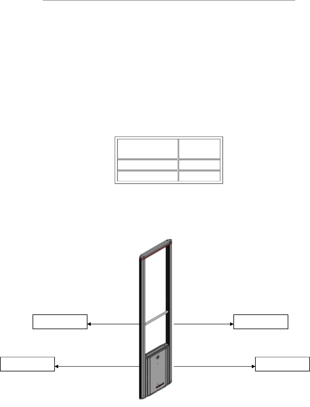
1.4 TEST RANGE
The type of antenna to be selected is a function of size of the tag and antenna
spacing. The table provides a reference for tag size versus maximum
allowable spacing. However, the spacing values shown on this table will
significantly decrease as the operating environment becomes harsher or
surrounded with such interfering environment as steel structures, power lines
located close to the antennas.
A walkabout on site test (installation procedures refer) will testify of the
maximum allowable spacing.
Figure 1.4
Tag Type MONO
410 tag 0.75 m
Mini Hard tag 1.0 m
410tag 0.75M 410tag 0.75M
Mini HT 1.0M Mini HT 1.0M
SIDEP
Page 9 of 19
2. GENERAL INSTALLATION
2.1 IMPLEMENTING ANTENNAS.
The Transceiver antenna (MONO) selection of location shall be a function of
the stores layout. The rear field is wider on transceiver system therefore
removes all furniture and hangers likely to contain anti-theft tags close to the
set-up, a minimum distance is recommended between antennas and shelf in
retail (1.5 to 1.8m).
Figure 2.1.
Detection zone
IMPORTANT NOTE
Prior to commencing the work (threading of cables, marking of locations, floor
drilling for antenna attachments…), perform a walkabout test on site in order to
assess the environmental impact. Depending on test outputs, the permanent
location of the antennas will be decided upon jointly with the client. Reduce the
antenna spacing whenever the operational environment does not provide
satisfactory results. Once the cabling is embedded and antennas are anchored
to the ground, it becomes a very difficult/costly and even an impossible job to
change antenna locations. Hence, this walkabout on site test is of a major
importance before commencing any installation work. The walkabout test will
make it possible for the fitter/installer to figure out any interference arising from
the environment. (subsection Interference Sources refers).
2.2 INTERFERENCE SOURCES.
Mains power generates interferences because of numerous parallel connected
appliances and devices (motors, spot lights, fluorescent lighting, etc…) and

SIDEP
Page 10 of 19
therefore, a dedicated line shall be provided directly from the switching board.
This line shall be installed by an approved installer.
A number of switching power supplies as used e.g., in Electronic Information
Systems (EIS) operate at a harmonic frequency similar to that of the EAS
SYSTEM and may cause system jamming and therefore, under no
circumstances should the power supply unit be connected to a line backed up
by an Uninterrupted Power Supply (UPS) (rectified current).
Metallic masses generate interference because of system absorbed and
reverberated electromagnetic waves.
Avoid installing antennas close to such metallic masses while keeping to a
minimum distance of 60 cm.
In case of implementing problems because of the site configuration, perform
testing in order to determine the best location.
Metal frames or guide bars sometimes behave like resonance circuits tuned to
the system frequency. Install antennas remotely from these structures or fit
bonding braids in order to cancel resonance phenomena.
Steel frames of doors sometimes behave in the same manner. Install antennas
remotely from such structures or fit shunts or bonding braids in order to cancel
resonance phenomena.
Position the system away from steel frame door(s), then open and close door(s)
and check the LED level bar for evidence of distorted signals (tag signal).
Defective fluorescent lighting, e.g. neon type, generates interference because
of permanent DC energizing on switching on. Please feel free to have this type
of lighting switched off and compare results with the LED level bar. Some
transformers used in this type of lighting appliances may be defective and
cause similar interference.
All electromagnetic field generating appliances typically incorporate
transformers, motors or mobile magnets, including: fluorescent neon tubes,
halogen quartz bulbs, cashiers conveyor belts, etc.
Power leads may also be a cause for interference. Prevent antennas from
standing too close to electrical leads. Move antennas and perform various
tests to assess the best location.

SIDEP
Page 11 of 19
3 Selection of Functioning Modes with DIP Switch:
Switch
Number Description
Switch 1
Cable Synchro Setting
ON: Master board
OFF: Slave board
Switch2
Power Synchro Mode
ON: Power synchronization(up to 4 systems on same
power line)
OFF: Power synchronization(up to 2 systems on separated
power line)
Switch 3
Synchro Increment – 5
th
systems
ON: Over 4 multiple systems synchronized by cable, every
5th system synchronized should have be on
OFF: At most 4 systems synchronized
Switch 4
Deactivator Synchro Mode
ON: Pulse Deactivator (SPD82) is synchronized by cable
Master board when cable synchronization
OFF: No deactivator
Switch 5
Tag/Noise Level Mode
ON: Normal sensitivity – Low noise environment
OFF: Low sensitivity – High noise environment
Switch 6
Sensitivity reduction Mode
ON: Standard System Sensitivity
OFF: Low Sensitivity
Switch 7
Automatic Level Mode
ON: The sensitivity level is automatically regulated
according to environment noise variation
OFF: The sensitivity is set by VR5
Switch 8
Deactivable Labels Protection Mode
ON: The transmission power level will automatically
decrease once a label is detected in order to avoid
deactivation of the label by the EAS system
OFF: Transmission power level Stable (recommended for
hard tag only system).
Default setting:
1 2 3 4 5 6 7 8
on off off off on on off off

SIDEP
Page 12 of 19
4. Basic Adjustment Procedure:
Basic adjustments procedure should be sufficient to set all necessary
parameters.
Other advanced adjustments and modification should be performed by
experienced technicians.
All other advanced parameters are set at factory and in most case the basic
adjustments method below would be enough to optimized the MONO system
performance.
4.1 Single System Adjustment
□ Set Switch 7 in position OFF (Automatic Level Mode Off).
□ Press SW1 to reset system.
□ Wait 1 minute for DSP to reboot.
□ Find the best position of antenna (lower LED Noise Bar Level).
□ Refer to previous instructions to find source of disturbance if the noise level
is high.
□ If necessary reduce VR5 to have less than 4 LED on (only green Led should
be on and 1 orange blinking).
□ Put back Switch 7 in Position : On
□ Press SW1 to reset system.
□ Wait 1 minutes for DSP to reboot.
5. Multiple System Synchronization
There are 3 different ways to synchronized multiple systems. As much as
possible try to use the external Synchro cable RG174 to synchronized multiple
systems. This method provides the most reliable synchronization. DS2 will be
lighted.
SIDEP
Page 13 of 19
5.1 External Synchronization Mode with cable (up to 25 systems by
230V 50Hz main power or up to 25 systems 120V 60Hz main power) :
The Master system is usually the antenna closest to the 230V 50Hz or 120V
60Hz power plug. Connect The RG174 synchronization cable from
Synchronize Out connector (master board) to Synchronize In (Slave board) and
to the next Slave system. Switch 1 should be in position ON for master board
and OFF for slave board.
When properly connected, the EXT SYNC LED of all the slave antenna boards
should be lighting excluding the master system’s LED which should be off.
Please ensure the cable is connected properly in polarity. Else the slave
systems’ Ext Sync LED is not lighting after connection.
If the EXT SYNC LED is twinkling, turn the VR1 of previous board to
make the EXT SYNC LED stable. Turn the VR1 to make sure each board has
no more than two noise LEDs.
If more than 5 systems are synchronized by cable, at each 5th system,
the Switch 3 (Synchronize Increment) should be in position ON.
5.2 Supply Synchronization Mode (up to 4 systems by 230V 50Hz main
power or up to 4 systems 120V 60Hz main power) :
Turn VR1 to make sure that its noise level is lowest. This synchronization is up
to support 4 systems on same power line or 2 systems on separated power
line.
5.3 Deactivator Synchronisation
For Sidep Pulse deactivator SDP82 the EAS systems should be synchronized:
Trimmer method:

SIDEP
Page 14 of 19
If less than 4 systems/deactivators are installed you may be able to
synchronized using only the SYN trimmer on SDP82 to set each devise with a
different time pulse.
External Synchro Method:
For more than 4 systems/deactivators using a RG174 synchro cable is
recommended:
□ Press SW1 to reset systems.
□ The green LED on the deactivator should be ON.
□ If green LED on the deactivator is bilking, change the SYN trimmer
adjustment on the deactivator.
6. TROUBLE SHOOTING
• False alarms / No detection / Orange/Red LED Noise Bar Level is
blinking fast and with regular intervals:
the most like reason is that another 8.2 MHz EAS system is installed nearby:
□ Put Switch 7 in position ON
□ Reset System
□ Turn SYN trimmer to find the best position
• Sporadic false alarms but with good detection and low LED noise Level:
This problem maybe caused by an external electrical disturbance or resonant
object nearby (metal/swing door…).
□ Turn the SYNC trimmer to find a better position.
□ If the problem persists set the Switch 5 in the position OFF
□ If the problem persists, set Switch 2 in the position ON and change SYNC
trimmer position to reduce random noise burst.
If the problem persists, refer to the pre-installation instruction to find the
possible source of disturbance. (Electrical interference, resonant object…)
• False alarm when touching antenna.
□ Look for possible resonant object
□ Change Antenna adjustment with Antenna Gain Adjustable capacitor.
□ If problem persists, set switch DIP 5 in the position OFF.
□ Reset system.
□ If problem persists switch the system to manual level control mode (switch 7
position OFF)
□ Press SW1 to reset system.

SIDEP
Page 15 of 19
□ Reduce the system sensitivity with VR5 until this problem stops.
□ Then switch the system back to the automatic level control mode (switch 7
position ON)
□ Press SW1 to reset system.
□ The detection will decrease, but functioning will be more stable and false
alarm less frequent.
• External Synchro Mode is not working even if cables are properly
connected (EXT SYN LED ON except Master System): A slave system must
have been powered on before its Master.
□ Switch off all systems
□ Switch on each system individually and in order starting from the Master
system.
• Labels are deactivated when passing near the MONO system:
□ Set Switch 8 in the position ON.
□ Press SW1 to reset system
To protect the label against deactivation due to high transmission Level, the
system will automatically decrease the output Transmission Level when a tag is
detected
System reaction may be slower and detection performance reduced.
7. Advanced adjustment of system parameters
7.1 LEDs DS11-18:
Press the SW2 button while holding it , you can see the signal number
corresponding the list below. When you release it you can see the value.
Number of LEDs being ON simulates the output of a particular signal .
• input signal (default after powering the system on)
• filtered input signal
• level of resonance caused by tags, metal construction, loops of wire,
etc)
• resultant input signal
• signal detection on each frequency (there are 8 frequencies transmitted)
• not yet used
• not yet used
• indication of sensitivity level reduction in automatic regime (DIP 7 ON).
(Example: 6 LEDs ON…80% of maximum or reduction by 20%)
SIDEP
Page 16 of 19
8. Connections from MONO board to Antenna
Figure 8.1.
+
+
+
RX
GND
LOOP
INPUT
POWER
BUZZER
TX 1
LAMP
+
RELAY
+
EXT LED
SYNC OUT SYNC IN DEAC
+
SIDEP
Page 17 of 19
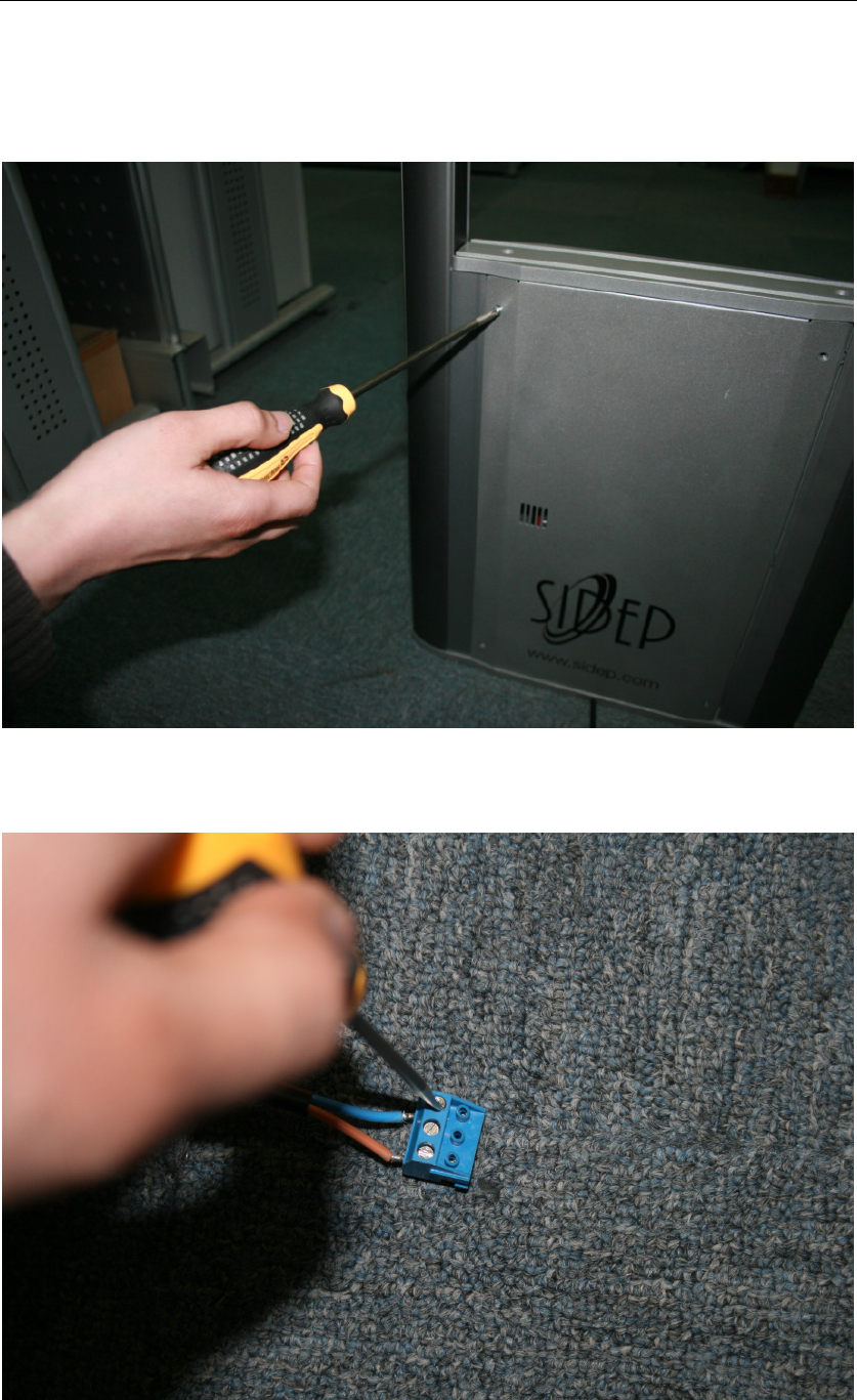
9. Mechanical installation
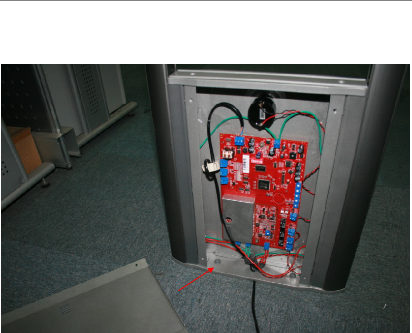
Step1: Unscrew the front cover.
Step2: Screw the power line terminal (no positive and negative).
SIDEP
Page 18 of 19
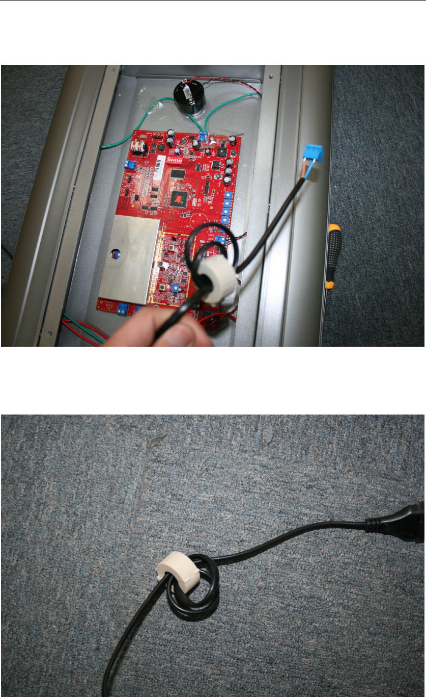
Step3: Drag the power line from the center bottom hole and make core around
by 3-loop line at the end of line.
Step4: Make the other core around by 3-loop line at the other end of line.
SIDEP
Page 19 of 19
Step5: Use two nuts to mount the antenna to the floor which has been
embedded with two bolts.
Step6: Screw the front cover again.