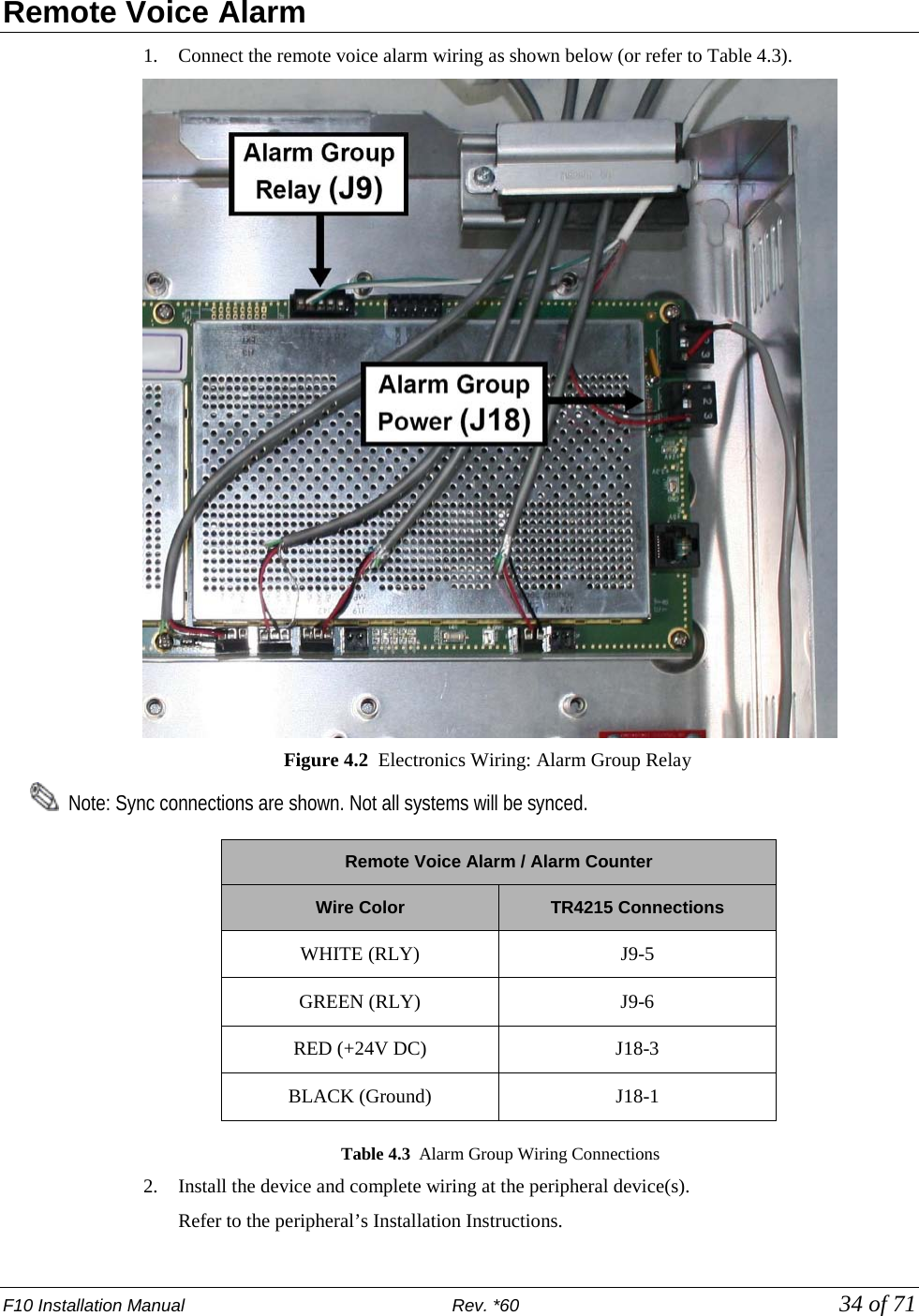
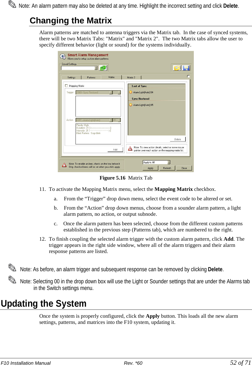
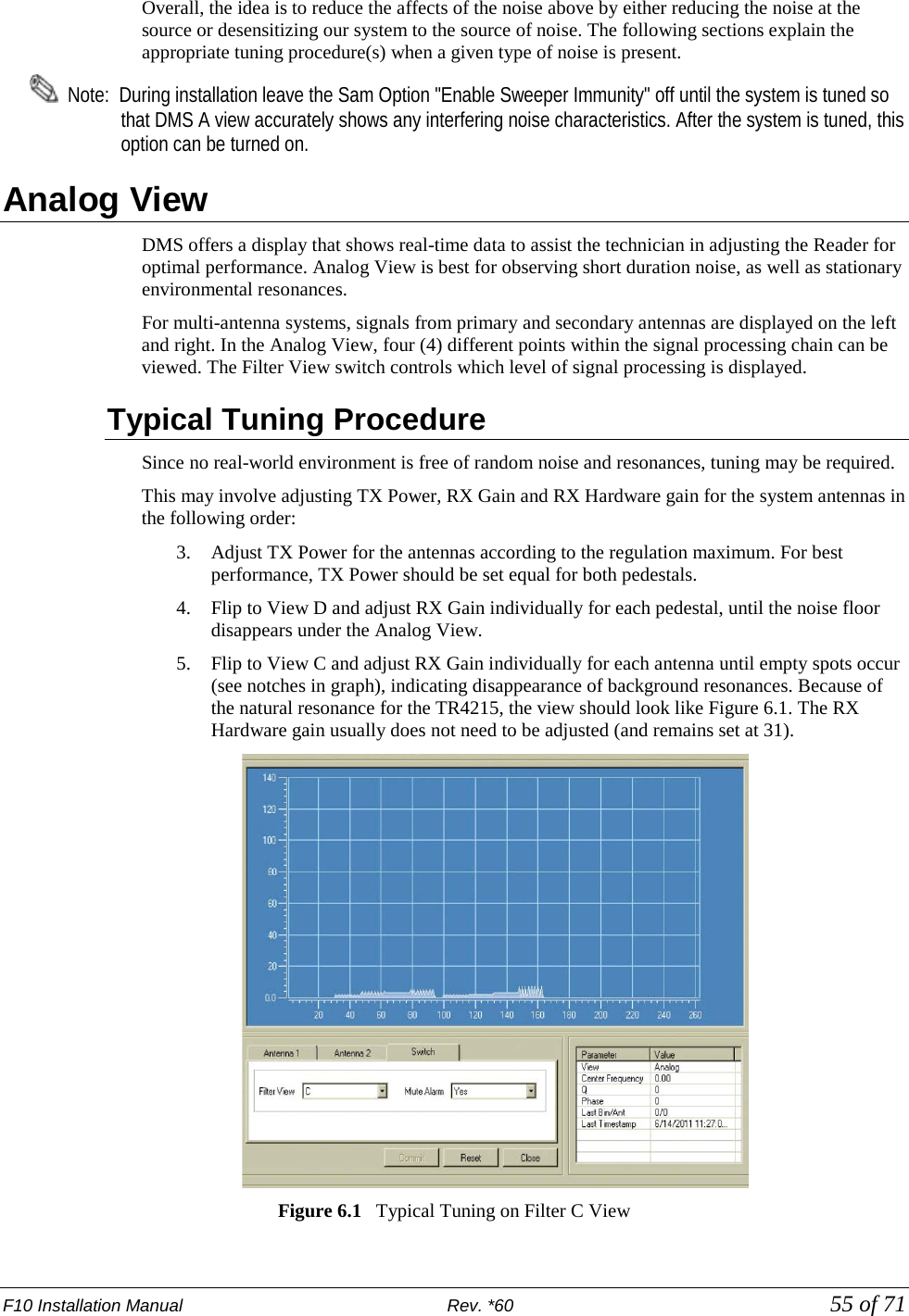
Checkpoint Systems EVOLVEF10 Electronic article surveillance detection system User Manual EVOLVE F10 Installation Manual
Checkpoint Systems Inc Electronic article surveillance detection system EVOLVE F10 Installation Manual
EVOLVE F10 Installation Manual

![F10 Installation Manual Rev. *60 3 of 71 Statements • The device(s) may only be used for the intended purpose designed by for the manufacturer. • Unauthorized changes and the use of spare parts and additional devices which have not been sold or recommended by the manufacturer may cause fire, electric shocks or injuries. Such unauthorized measures shall exclude any liability by the manufacturer. • The liability-prescriptions of the manufacturer in the issue valid at the time of purchase are valid for the device. The manufacturer shall not be held legally responsible for inaccuracies, errors, or omissions in the manual or automatically set parameters for a device or for an incorrect application of a device. • Repairs may only be executed by the manufacturer. • Installation, operation, and maintenance procedures should only be carried out by qualified personnel. • Use of the device and its installation must be in accordance with national legal requirements and local electrical codes. • When working on devices the valid safety regulations must be observed. • Before touching the device, the power supply must always be interrupted. Make sure that the device is without voltage by measuring. The fading of an operation control (LED) is not an indicator for an interrupted power supply or the device being out of voltage! • The installer or licensed electrician must follow all NEC and local codes. • All wires routed in the floor per article 725 must be Class 2 and be UL Listed. UL Recognized AWM may be employed, provided it is enclosed in Conduit or ENT. • The F10 is not to be installed in Wet Locations. For indoor use only. • Checkpoint is not responsible for or warrant any repairs or rework to the flooring during or after the installation of the antenna. Guide Conventions Document conventions are described below: This is a Warning icon. When it appears, it indicates a potentially hazardous situation, which if not avoided, could result in death or serious injury. Caution: This is a Caution icon. When it appears, it indicates a potentially hazardous situation which if not avoided, could result in property damage or malfunction of equipment. Note: This is a Tip icon. When it appears, the corresponding text indicates a helpful note or tip when using the feature. For all measurements: • To meet both CE and FCC requirements, all measurements will be listed in the following format: Metric [Imperial], for example: 46cm [18in] or 0.9m [3ft]. • Where non-S.I. units are applicable, such as 6’ x 4’ or 3/16”, the format in this case is Unit (metric). Where on-screen computer instructions are given: Button Name - This describes a button or an on-screen command or drop-down selection. For example, the <DONE> button is represented in this document as Done. Key Name - This describes a keystroke on a keyboard. For example, Ctrl represents the control key.](https://usermanual.wiki/Checkpoint-Systems/EVOLVEF10/User-Guide-1891276-Page-3.png)


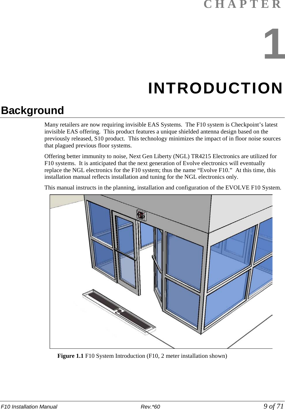
![F10 Installation Manual Rev. *60 11 of 71 System Diagrams The F10 system uses an antenna assembly comprised of wire coils wrapped around ferrite material tiles. Antennas are enclosed in PVC casings for strength and protection from environmental factors. Figures 1.4 and 1.5 show common installation coverage widths: 2m and 3m [6 and 9ft respectively]. Figure 1.4 Typical F10, 2 Meter Installation Figure 1.5 3m [9ft] Installation Layout with Component Names](https://usermanual.wiki/Checkpoint-Systems/EVOLVEF10/User-Guide-1891276-Page-11.png)
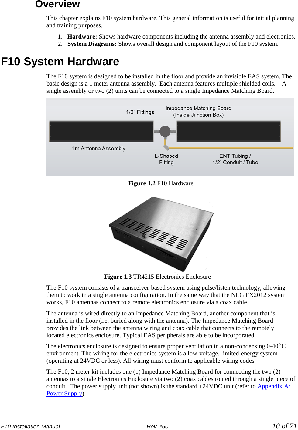
![F10 Installation Manual Rev. *60 12 of 71 Grouping Multiple Antennas Larger aisles are able to be covered using a Sync configuration. Aisle widths of any 1m increment are possible. The 3m configuration features an F10, 2 meter system and a single 1 meter system. Similarly, the 5m layout features two (2) F10, 2 meter systems and the standard F10 antenna. Multiple electronics enclosures and power supplies are required, in this case, and the system electronics must be configured for operation as a single unit. Refer to the “Wiring Between Systems for Sync” section. Multiple floor trenches are cut with each length of ENT tubing (conduit) spaced 5.1 cm [2in] from the next closest to reduce RF interference. Although grouping multiple installation kits together is possible, it requires approval from Checkpoint’s Product Management. Feasibility is confirmed during the initial planning stage known as the “Site Survey.” If the Site Survey was already performed and at present you are prepared with installation-specific details, please skip to Chapter 3: Physical Installation. 2 x 1 Meter Configuration When necessary, two (2) standard F10, 1meter systems are connected to the same electronics enclosure in a 2 x 1 meter configuration. The common application of the F10, 2 x 1 meter configuration is in a grocery store or large department store. This setup allows EAS coverage of many store checkout aisles, as well as single-door entrance / exit layouts. Each 1m antenna assembly is fitted with a Matching Board. The layout minimizes the total number of electronics enclosures needed when multiple F10 systems are used. Figure 1.6 F10, 2 x 1 Meter System Diagram](https://usermanual.wiki/Checkpoint-Systems/EVOLVEF10/User-Guide-1891276-Page-12.png)
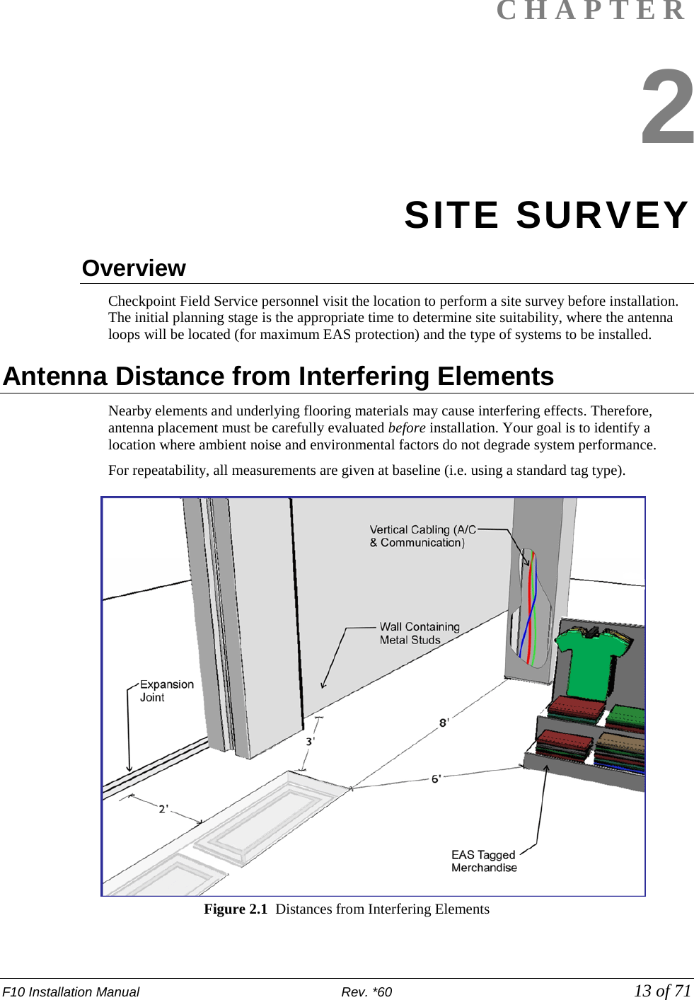
![F10 Installation Manual Rev. *60 14 of 71 Common interfering elements and their minimum distances from F10 Antennas are listed below: Expansion Joints: The minimum distance from an expansion joint is 0.6 m [2 ft]. Vertical Cabling: The minimum distance from vertical cabling is 2.4 m [8 ft]. Metal Wall Studs: The minimum distance from a metal wall stud is 0.9 m [3 ft]. Sliding Doors (Metal): The minimum distance from a metal sliding door is 1.2 m [4 ft]. Tagged Merchandise: The minimum distance from tagged merchandise is 1.8 m [6 ft]. Inward and Outward Swinging Doors (Metal): The minimum distance from either a manual- or automatic-swinging metal door frame is 0.6 m [2 ft]. Although this last type of door is not shown in the figure, the fact that swinging metal doors can swing toward the antenna loop must be taken into account (see below). Note: The antenna must not be located below the door (or too near the door) when fully opened. Locate the F10 antenna components beyond the door – with a minimum clearance gap of 0.6m [24in]. Other Checkpoint equipment could interfere with the F10 system or vice se versa (refer to Appendix C: Interactions for recommended separation distances). System Performance Considerations Nearby wiring and lighting, as well as floor construction, may affect performance. With RF interference that is too severe and cannot be alleviated, the site may not be suitable for any installations. The detection field is not uniform (refer to Appendix D: Detection Performance for diagrams). Each of the following alters F10 system performance: • Spacing between the antenna and steel deck in the floor can affect performance, but it has been observed that an increase in detection can occur when the F10 system is placed on any metal flooring. • Floor structure may cause detection variation for the F10 system. • Antenna configuration will cause an expected (known) change in detection heights and a unique coverage pattern. Refer to Appendix D: Detection Performance for detail. • Signal strength - The plots in the appendix have a defined height at TX = 31 (the maximum). If TX is less than 31, detection heights will decrease. Determining the Electronics Location During the site survey, evaluate the store’s layout to learn what options are available for locating the electronics enclosure and power supply. The electronics and power supply may be placed close together, although this is not required. Both units may be placed under a cashwrap counter, under shelving, above a drop ceiling (see special requirements), or in a utility closet. The updated power supply can be installed in the plenum (i.e., above a drop ceiling or in HVAC areas), but this requires a conversion kit (refer to Appendix A: Power Supply for complete details). If necessary, the electronics enclosure can be located in the plenum – and as long as the power supply is located outside of the plenum – no conversion kit is required. Note: Since the “Hood Kit” (CKP P/N: 7367100) must be ordered separately, determine whether or not one is needed now. Caution: If using the conversion kit, the power supply must be installed by a licensed electrician.](https://usermanual.wiki/Checkpoint-Systems/EVOLVEF10/User-Guide-1891276-Page-14.png)
![F10 Installation Manual Rev. *60 15 of 71 Electronics Enclosure Placement Requirements • Locate the electronics enclosure no further than 12.2m (40 linear-feet) or 15.2m (50 cable-feet) from the antenna(s) to allow for bends in the conduit run. • If wall-mounting is ideal, mount the electronics enclosure approximately 1.8m [6ft] above the floor to reduce RF-interaction with wiring in either the ceiling or the floor. Electronics mounted to the ceiling can potentially have a high RF-interaction with the surrounding environment (e.g., metal rafters or power cables), and therefore, may not perform optimally here. Observe locations of active noise sources including deactivators. Environmental Considerations F10 systems are only approved for indoor installations only. For a first floor (ground level) installation where the slab will be on grade (i.e., directly above the natural ground), we recommend the concrete be poured above a vapor barrier to prevent moisture from rising. The store's architect will recommend the maximum permissible loading in the floor area where F10 antennas are physically installed. The architect must consider such factors as anticipated traffic over the floor and the material characteristics of the flooring (if covered by concrete). The guidelines included in this guide assume installation into concrete (typical), but the antennas may be placed directly on concrete if flooring, such as finished hardwood, laminate, tile or stone, conceals the system below. If a wooden floor is placed on top of the system, the weight of the floor should not rest on the antenna(s). Moreover, with all installations, the concrete and other materials above the antenna(s) cannot be metallic. For example, wire mesh cannot be used for reinforcement above the concrete. Metallic walk-off mats should not be placed above the system. Note: Tile grout and mortar used to fill antenna trenches MUST BE non-metallic and non-magnetic grout. Another environmental consideration is a metal security gate. For installations where the drop down or sliding gate could cause a phantom alarming issue, a Badge Board II (CKP P/N 7528451) and a Gate Inhibit Switch (CKP P/N 7140188) should be installed. Discuss with Product Management and customers. As for the electronics, typical indoor conditions must be met. Operating temperature is 0°C to +40°C [32° to 104°F]. Permissible humidity range is 10 to 75%. Site Survey Conclusion Overall, the site survey is an opportunity to gather details and share information required for the proper installation workflow. Before leaving the test site, the location of the electronics enclosure, floor cuts (trenches or “channels”), and/or conduit runs (see note) should be documented. Using the information in the following chapter, draw up a plan with exact dimensions. In addition to floor cuts, the power outlet locations (or hardwire into electrical for plenum installation) should be planned. Coordinating with site contractors facilitates easier installation. Note: For the F10 System, it is required that the coax cable is ran through ENT Tubing (conduit). Communicate with the contractor (and/or store personnel) before concrete has been poured. This crucial action will allow the coax cable to be easily routed through the conduit. Caution: Ensure wire run does not exceed the maximum distance to the electronics’ planned location.](https://usermanual.wiki/Checkpoint-Systems/EVOLVEF10/User-Guide-1891276-Page-15.png)
![F10 Installation Manual Rev. *60 17 of 71 Parts Quantity will vary according to system type. 18 AWG 2-conductor (STP) Power 22 AWG 4-conductor (STP) (5594) Sync PVC cement *DekDuct (wire chase) *Wiremold (1500 or 2600 series) *Wiremold anchor bolts Note: *Wire routing methods will vary by installation. Note: Complete parts lists with OEM Part Numbers are included in Appendix B: Part Lists. Installation Outline Follow this sequence to successfully install the components and validate system operation: 1. Determine optimal antenna placement: a. Perform a site survey now, or b. Use the results of a previous survey. 2. Determine power supply requirements and the ideal location for system electronics. 3. Physically install the antenna(s). 4. Route/connect the antenna (coax cable) and applicable wiring (sync, alarm, power). 5. Install the peripherals and wire the device(s) to the electronics enclosure. 6. Configure the system using DMS. 7. Perform system specific tuning (test jump positions). Antenna Installation Antenna installation and tuning is performed by trained Checkpoint personnel. You have already determined the system model(s) and number of assemblies for install, or you recently received this key information from a prior survey. If you are unsure of any specifics, contact Checkpoint Project Management. Install the antenna(s) in the proper location(s) discovered during the site survey. During Construction If the floor has not been poured yet, a pre-fabricated trough can be constructed. Refer to Figures 3.3 and 3.4. In the event of a new construction, please convey the following information to the site contractors (construction team’s foreman) or the manager responsible for pouring the concrete: • Location where antenna (s) will be placed; define a reference point (such as a door frame). • The exact dimensions of antenna(s); provide the appropriate Floor Cut diagram(s). • The depth, length and pathway of the 1/2” ENT Tubing (conduit), if installed ahead of time; depth of the trench for routing the cable is 3.8cm [1.5in] deep. After Construction For sites where floor cuts must be made, convey the following instructions to the installing technician. Communicate all known specifics to the installer, referring to the diagram(s). Be sure to convey plans and instructions for the correct system type. Only provide the floor layout(s) for required antenna configuration(s). If using a chisel, rough / uneven floor cuts may occur. Flatten the bottom surface on which the antenna rests with either leveling sand or a layer of concrete fill.](https://usermanual.wiki/Checkpoint-Systems/EVOLVEF10/User-Guide-1891276-Page-17.png)
![F10 Installation Manual Rev. *60 18 of 71 Caution: Prevent uneven stress on the fragile electronic components inside the assembly by ensuring the floor trough is smooth and level. Fill in uneven areas or gaps with leveling sand or concrete filler. F10, 1 Meter and 2 Meter Floor Cuts Installing the F10 antenna assembly in an existing store requires a trough to be cut in the floor. If the site is under construction, it is easier to mold the system into the floor (explained above). These diagrams include details on the size of the trough cuts required for each configuration. Note: Figures are Not Drawn to Scale 127.6cm [50.25in]35.5cm[14in] F10 MatchingBoard Location Figure 3.1 Top View of F10, 1 Meter Floor Cut F10 MatchingBoard Location21.8cm [8.6in]234.5cm [92.33in]35.5cm[14in] Figure 3.2 Top View of F10, 2 Meter Floor Cut Figure 3.3 Trough for the 2 Meter assembly](https://usermanual.wiki/Checkpoint-Systems/EVOLVEF10/User-Guide-1891276-Page-18.png)
![F10 Installation Manual Rev. *60 19 of 71 Floor Cut Depth F10, 1 meter and 2 meter Antennas are identical, so the trough’s floor cut depth (height) is always consistent. Recommended depth is 7.6cm [3in] for optimum structural integrity. This allows approximately 3.75cm [1.5in] of concrete top fill covering each antenna (as shown in Figure 3.3). Figure 3.3 Side View of Trough Figure 3.4 Antenna Installed (not buried until after testing) In scenarios where the flooring does NOT physically allow such depth, it is acceptable to cover the antenna assembly with less than 1.5 inches of concrete fill. Although it is uncommon, when covering with tile or wood flooring, the system can be installed flush to the concrete’s surface. Figure 3.5 Flush Depth Note: If installing in a location that violates the recommended 7.6cm [3in] depth specification, inform Checkpoint Project Management.](https://usermanual.wiki/Checkpoint-Systems/EVOLVEF10/User-Guide-1891276-Page-19.png)
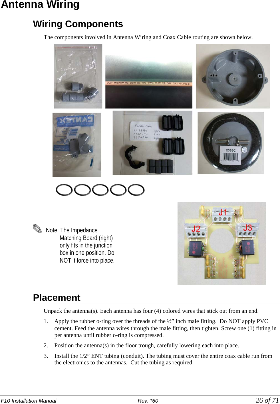
![F10 Installation Manual Rev. *60 20 of 71 Common Wider Floor Cuts It is possible to create a wider system by combing either of the smaller two floor kits (refer to Figures 3.1 and 3.2 above). For example, to cover a 3m mall opening, a 1m and 2m kit are ordered. Figure 3.6 below shows exact dimensions of the trough (floor cuts) when the F10, 1 meter and 2 meter systems are combined. Figure 3.7 shows two (2) F10, 2 meter systems installed side-by-side. 354.5cm [139.6in]Matching BoardLocations 117.5cm [46.27in]224.2cm [88.3in]35.5cm[14in]21.8cm [8.6in] Figure 3.6 2m and 1m System for 3m Opening Note: Figures are Not Drawn to Scale 461cm [181.5in]Matching Board Locations35.5cm[14in]117.5cm [46.27in] 117.5cm [46.27in] Figure 3.7 Side-by-Side 2m Systems for 4m Opening Note: The Impedance Matching Board placement for the F10, 2 meter system is between the assemblies. For the F10, 1 meter system, board placement is beside the antenna assembly. The ENT Tubing (with coax cable) can be routed in any direction from antenna to electronics. A minimum spacing of 2” between the antenna and tubing is required.](https://usermanual.wiki/Checkpoint-Systems/EVOLVEF10/User-Guide-1891276-Page-20.png)
![F10 Installation Manual Rev. *60 21 of 71 Mounting the Electronics Enclosure Detailed instructions for mounting the Electronics Enclosure are below. Before installing the enclosure, review the following requirements and if necessary, consult the Site Survey results. It is suggested if the location is difficult to access, wire the system before mounting, but keep the power supply unplugged until finished wiring all peripherals and mounting the support brackets. The electronics enclosure must be located no further than 12.2 linear-meters [40 linear-feet] from the antenna(s) to allow for bends in the 15.2 cable meters run [50 cable feet]. The enclosure, which weighs 5.17kg [11.4lbs], has keyhole slots at its edges to facilitate wall-mounting, but the enclosure must have 2.5cm [1 in] clearance on all sides. Do not mount the electronics enclosure beneath potential water sources (e.g. a sprinkler or pipe). It is suggested to locate the enclosure directly above (or nearest to) the conduit’s endpoint, so the length of exposed coax cable is minimal. Limiting exposed cable prevents RF interference, but do not cut the coax cable (refer to the “Placement” section in Chapter 4: Wiring). Using the included ENT Tubing (flexible conduit is supplied in the kit), route the cable from the matching board to the arrival point near the electronics enclosure. Installation procedures are listed for each type of material on which the enclosure can be installed: • Wood Surface, • Drywall, and • Concrete.](https://usermanual.wiki/Checkpoint-Systems/EVOLVEF10/User-Guide-1891276-Page-21.png)
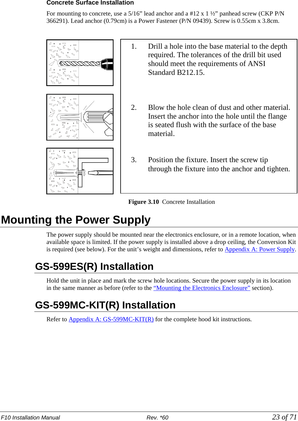
![F10 Installation Manual Rev. *60 22 of 71 Wood Surface Installation For mounting to wood, use a #7 x ½” (0.38cm x 1.3cm) hex head screw (CKP P/N 7939172). Figure 3.8 Wood Surface Installation Drywall Surface Installation For mounting to drywall, use a #8 x 1” (0.42cm x 2.5cm) panhead screw (CKP P/N 7308823), which is a Power Fastener Zip-it (P/N 02348). Figure 3.9 Drywall Installation 1. Using the proper diameter bit, drill a hole into the base material to a depth of at least 0.6cm [1/4”] deeper than the embedment required. Blow the hole clean of dust and other material. 2. Select the installation tool and drive socket to be used. Insert the head of the screw into the hex head socket driver. 3. Place the point of the screw through the fixture into the pre-drilled hole and drive the anchor in one steady continuous motion until it is fully seated at the proper embedment. 1. Insert either # 2 or # 3 Phillips driver bit into the recess of the ZiP-It anchor head. Use a manual screwdriver or a low-rpm battery-powered electric screw gun. 2. Push the ZiP-It anchor into the surface of the wallboard until the two cutting blades penetrate the surface. Using gentle forward pressure, rotate the ZiP-It until the collar sets flush to the surface of the wall. 3. Put the fixture in place, insert screw and tighten until it feels secure. As the screw is threaded into the nylon versions, the point will expand resulting in increased load capacity in thicker wallboard. Note: When using an electric screw gun for application, set clutch and use a slow speed (do not exceed approximately 300-400 RPM).](https://usermanual.wiki/Checkpoint-Systems/EVOLVEF10/User-Guide-1891276-Page-22.png)

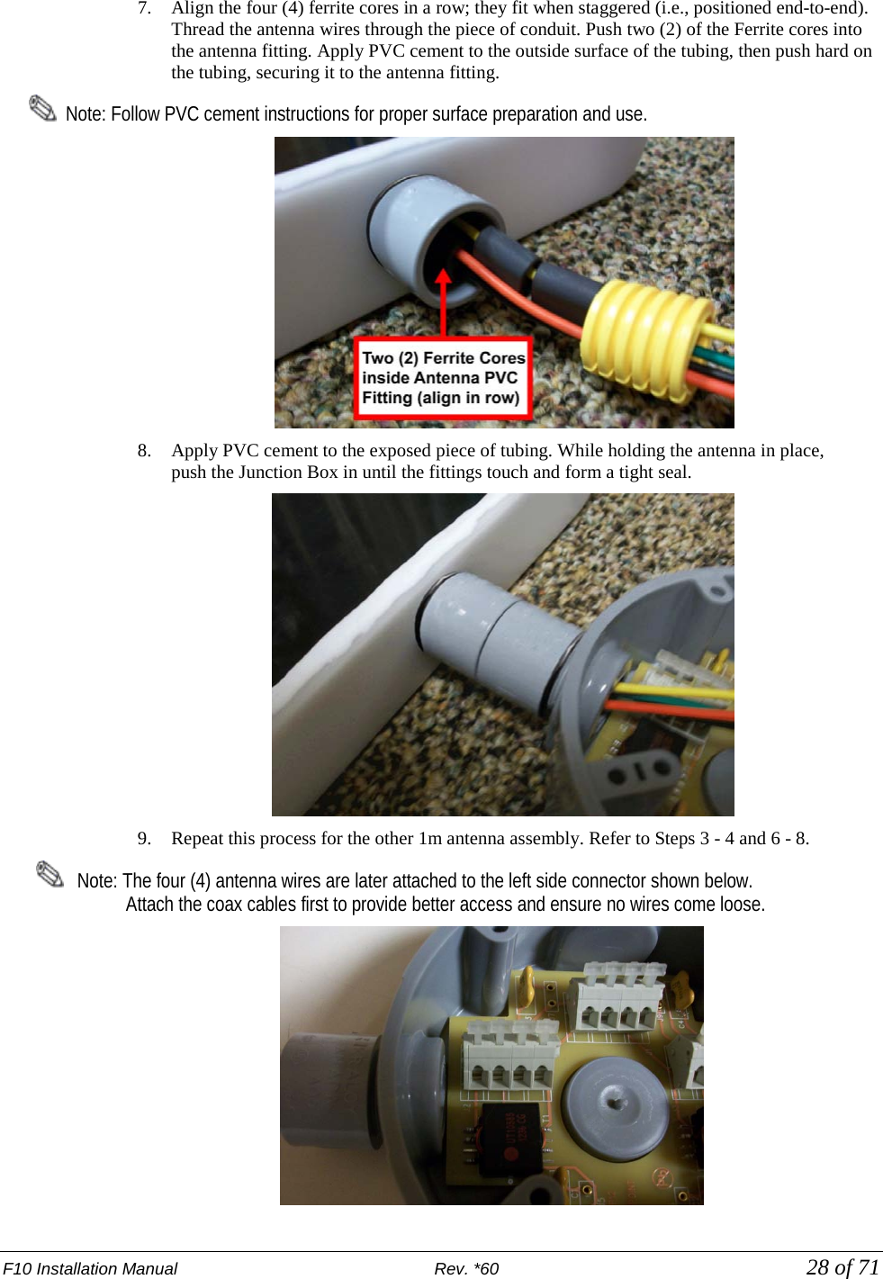
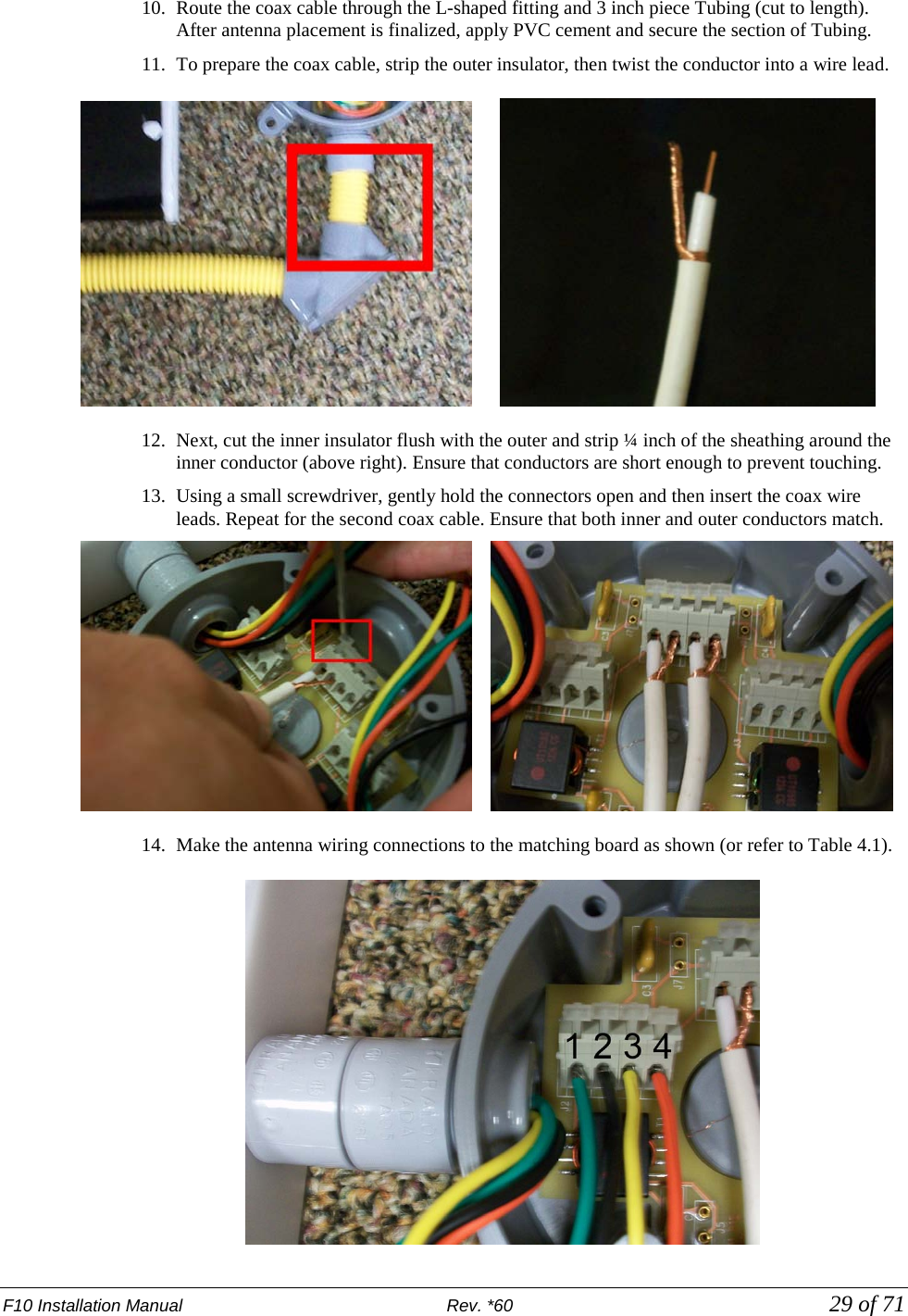
![F10 Installation Manual Rev. *60 27 of 71 4. Route the coax cable from the Electronics Enclosure to the floor trough. Do not cut the cable yet, but note that excess will be removed after the true length is determined. Caution: Cable must not be cut shorter than 30’. 5. Unpack the remaining system components including the Junction Box, lid, Impedance Matching Board, PVC fittings and ferrite cores. Wiring the F10, 2 Meter System Perform the following to wire the F10, 2 meter system to the Impedance Matching Board. 1. Identify the “top” of the Junction Box (with the Carlon® logo facing up) and position the box as shown. Remove the left, right and bottom knockouts from the Junction Box. Use a hammer and a large screwdriver as shown. Caution: Ensure the correct knockouts (3 sides shown) are removed for the 2 meter system (only 2 for 1 meter system). Since the 2 meter uses both TX1 and TX2 sets of input connectors, set up is different. 2. Apply the rubber o-ring over the threads of the ½” inch male fitting. Do NOT apply PVC cement. Screw the fitting into the opening where the knockout was located until rubber o-ring is compressed. Repeat for the other locations; tighten three (3) fittings in total. 3. Identify the colored antennas wires. Twist together loose strands of any frayed wire. 4. Select any four (4) small ferrite cores (CKP P/N 7221412). 5. Group the Yellow and Green wires together. Thread each individual lead through the same opening in each of two (2) Ferrite cores. Repeat for the set of Red and Black wires as shown. 6. Using a utility knife (shown at far right), cut two (2) pieces of conduit with six (6) rings for each (approximately 2.54cm [1in] in length). Cut a third piece approx. 7.5cm [3in] long. This section connects at the L-shaped fitting (see Step 10).](https://usermanual.wiki/Checkpoint-Systems/EVOLVEF10/User-Guide-1891276-Page-27.png)
![F10 Installation Manual Rev. *60 30 of 71 15. The right side antenna is wired in reverse. Red connects to pin 1, yellow to pin 2, etc. Side Pin Number Antenna Wiring Antenna 1 (Left) J2-1 Green J2-2 Black J2-3 Yellow J2-4 Red Antenna 2 (Right) J2-1 Red J2-2 Yellow J2-3 Black J2-4 Green Table 4.1 F20 Antenna Wire Pinout 16. Verify the correct pin-out using the above table. Note: Before closing the lid, it is necessary to first evaluate system performance. Refer to Evaluate Jumper Positions. 17. Ensure that all the connections are secure (gently pull on the leads at the connection point to the circuit board). Carefully position the wires inside, then close the Junction Box lid (tighten all 4 screws). Be careful not to tear or twist the foam gasket on the lid when tightening the screws. Note: In instances where multiple electronics and coax cables are used, ensure that floor trenches or conduits are spaced 5cm [approx. 2in] apart.](https://usermanual.wiki/Checkpoint-Systems/EVOLVEF10/User-Guide-1891276-Page-30.png)
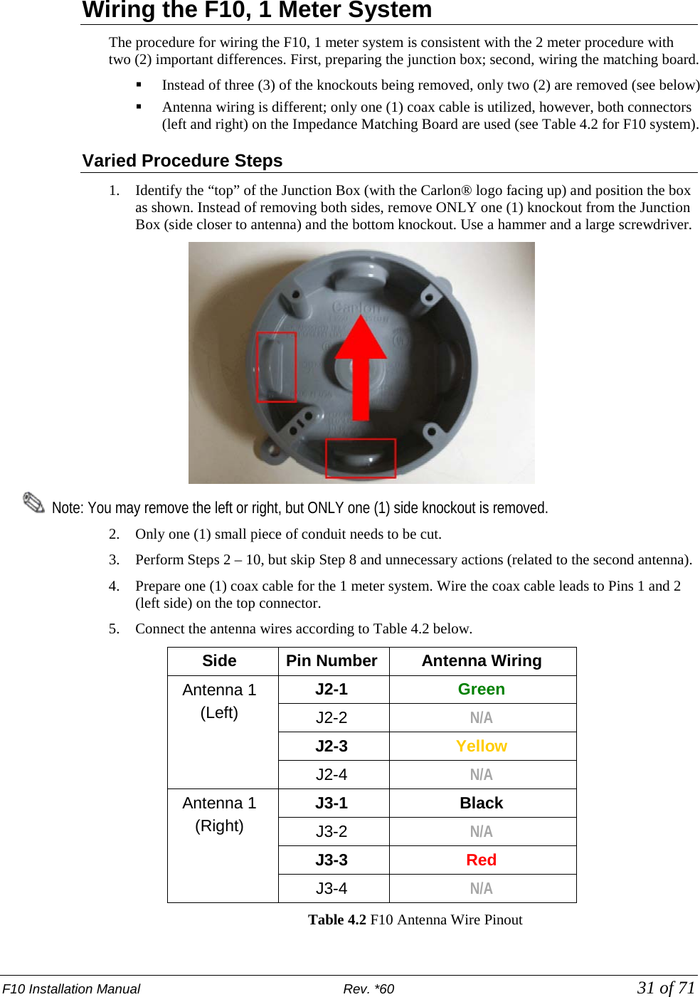
![F10 Installation Manual Rev. *60 32 of 71 Adjusting Jumper Settings The default jumper settings for the F10, 2 meter system are OUT for J5 - J10. The settings are adjusted for the F10, 1 meter system. Insert the red J5 and J6 jumpers. Note: Later on, after the system is initially configured, each of the jumper positions are tested in order to optimize the tuning of the F10 antenna. Refer to Evaluate Jumper Positions and complete the test. Wiring the 2 x 1 Meter System For the 2 x 1 meter configuration, the wiring to each antenna is consistent with the F10, 1 meter procedure. The main difference is there are two (2) coax cables routed to the electronics enclosure. Route each coax cable separately through two different pieces of ENT Tubing. The lengths of coax cable are connected to the two (2) male connectors on the A1116 Coax Adapter Board. Note: In instances where multiple electronics and coax cables are used, ensure that floor trenches or conduits are spaced 5cm [approx. 2in] apart.](https://usermanual.wiki/Checkpoint-Systems/EVOLVEF10/User-Guide-1891276-Page-32.png)
![F10 Installation Manual Rev. *60 33 of 71 Overview Electronic interfaces / connections to the TR4215 reader board are shown below. This section describes how to wire all cables and make the appropriate connections at the Electronics Enclosure. Figure 4.1 TR4215 Board with all interfaces labeled Coax Cable / A1116 Wiring The A1116 Coax Adapter Board connects to the F10 antenna via 15m [50ft] coax cable(s). 1. Connect the coax cable to the A1116 adapter board, then clip the Ferrite core (CKP P/N 7784420) over the cable(s). Note: Ensure that the two (2) output jumpers are in the Remote Position. J37 and J38 on the TR4215 board are located just above the A1116 Adapter Board.](https://usermanual.wiki/Checkpoint-Systems/EVOLVEF10/User-Guide-1891276-Page-33.png)
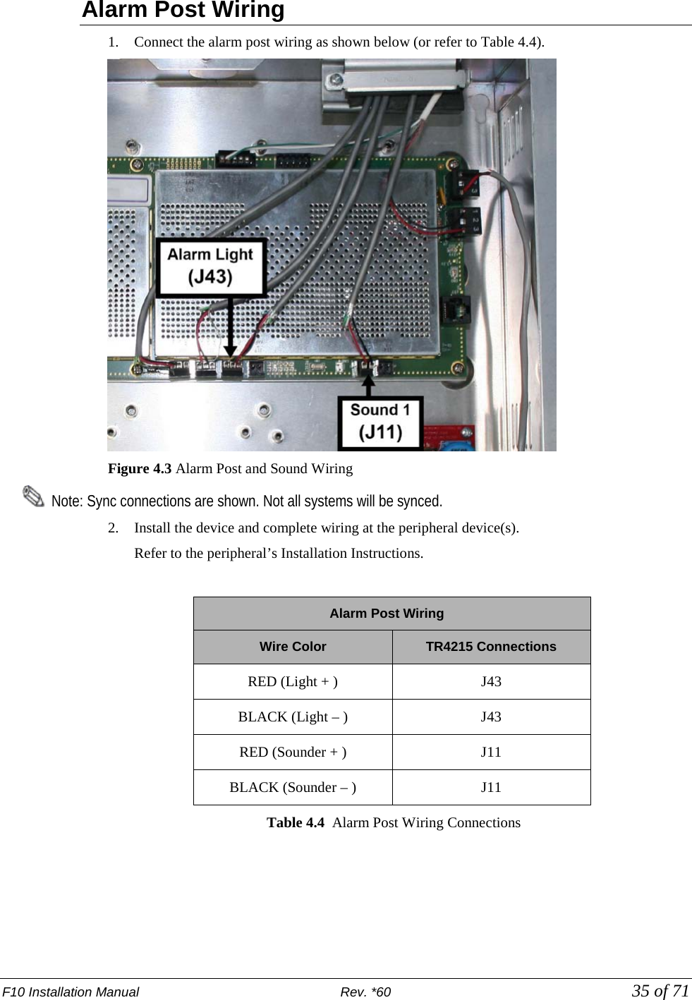
![F10 Installation Manual Rev. *60 36 of 71 24VDC Power Supply Wiring Below are instructions for wiring the 24VDC power supply to the TR4215 board’s DC Input Filter. 1. Cut the MC Armored cable (or generic AWG18 plenum-rated power cable) to length. 2. Strip the 2 (two) leads exposing about 0.6 cm [0.25 in] of the conductors. 3. Apply a Ferrite Core (CKP P/N 7284760) on the power wire near the DC Filter board; complete 3 loops. 4. Apply the Ferrite Core (CKP P/N 7284760) to the AC power cord. Figure 14.4 AC Power Cord Ferrite 5. Connect the leads to the DC inputs as shown (or refer to Table 5.5 below). Figure 4.5 Power Supply connections (for a Single-Antenna System) Figure 4.6 DC Power Filter _______ (Parallel outputs on left and right) Wire Color Description Black GND Red +24 V Table 4.5: Power Cable Wiring Connections](https://usermanual.wiki/Checkpoint-Systems/EVOLVEF10/User-Guide-1891276-Page-36.png)
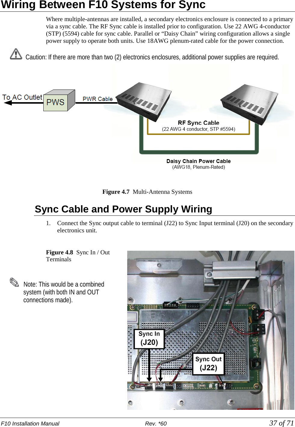
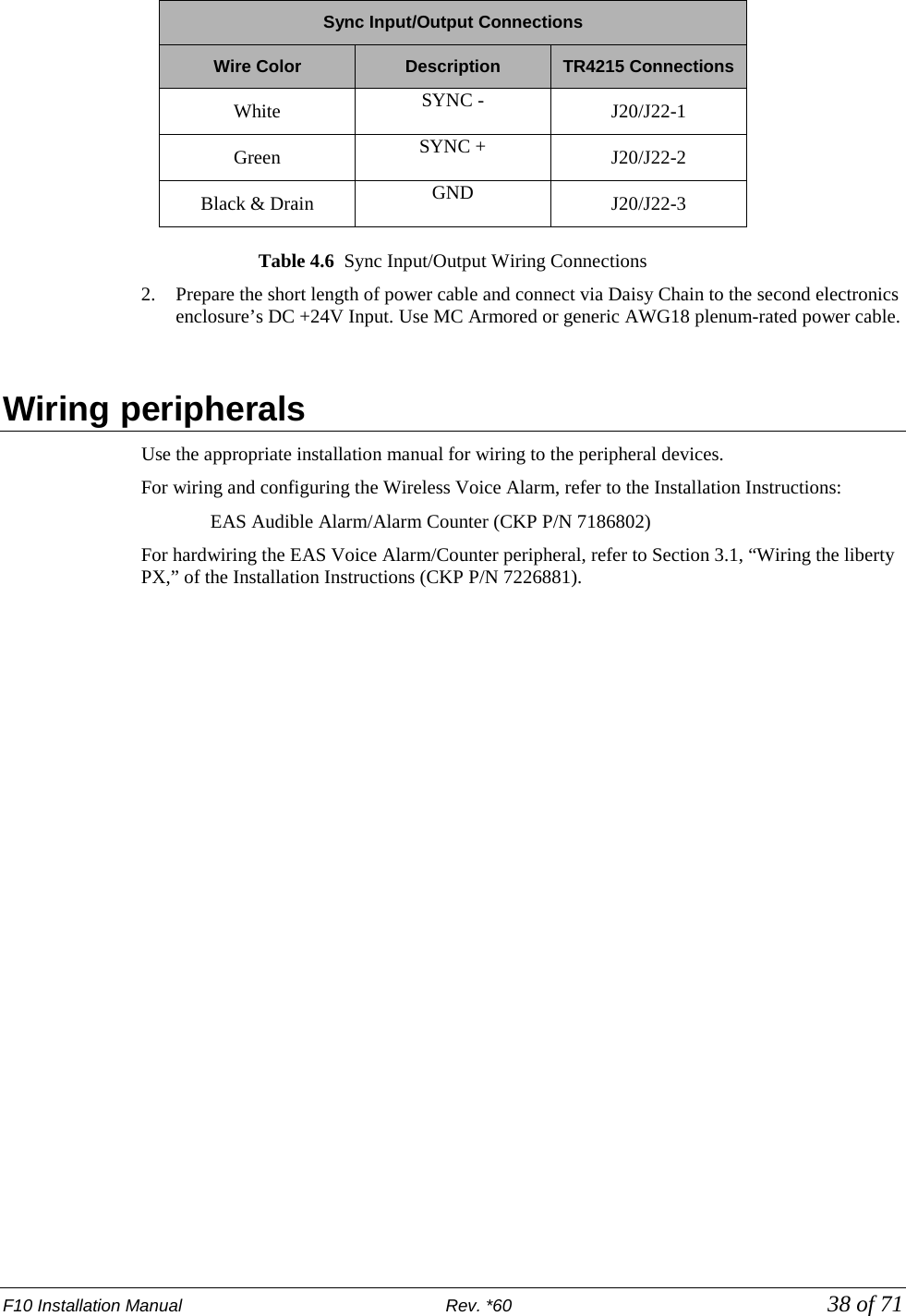
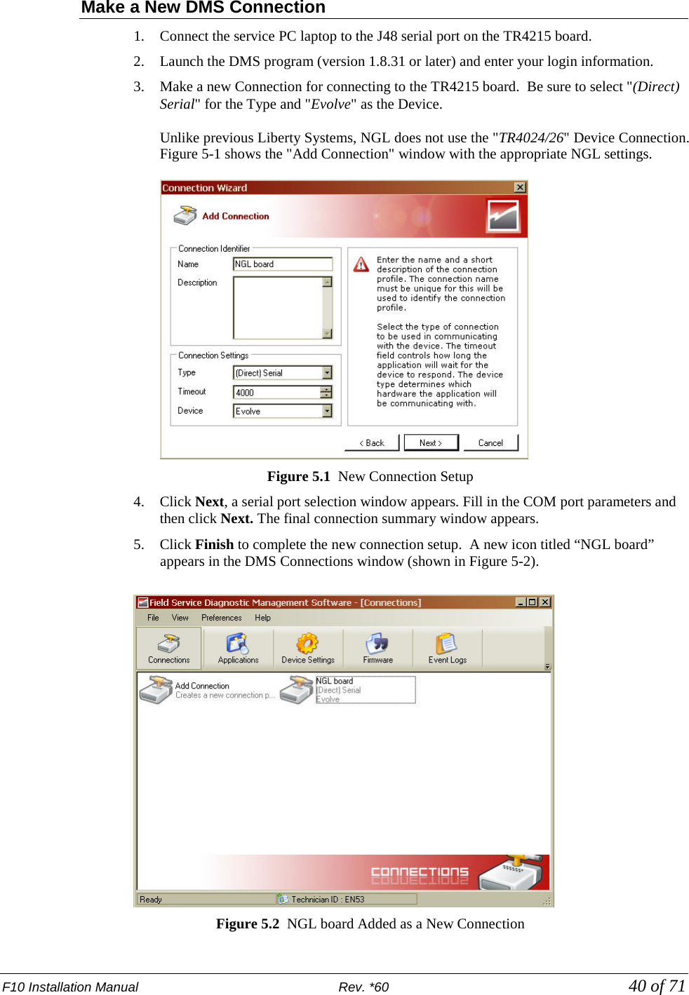
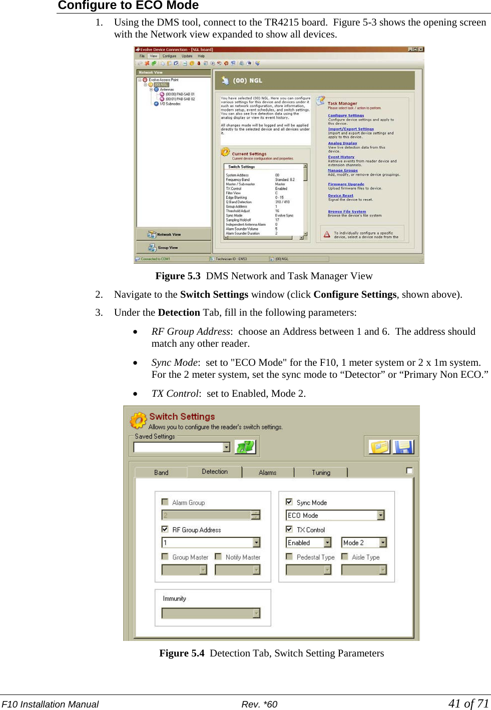
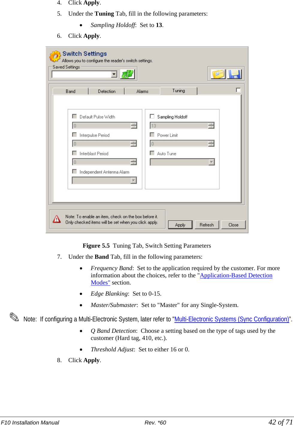
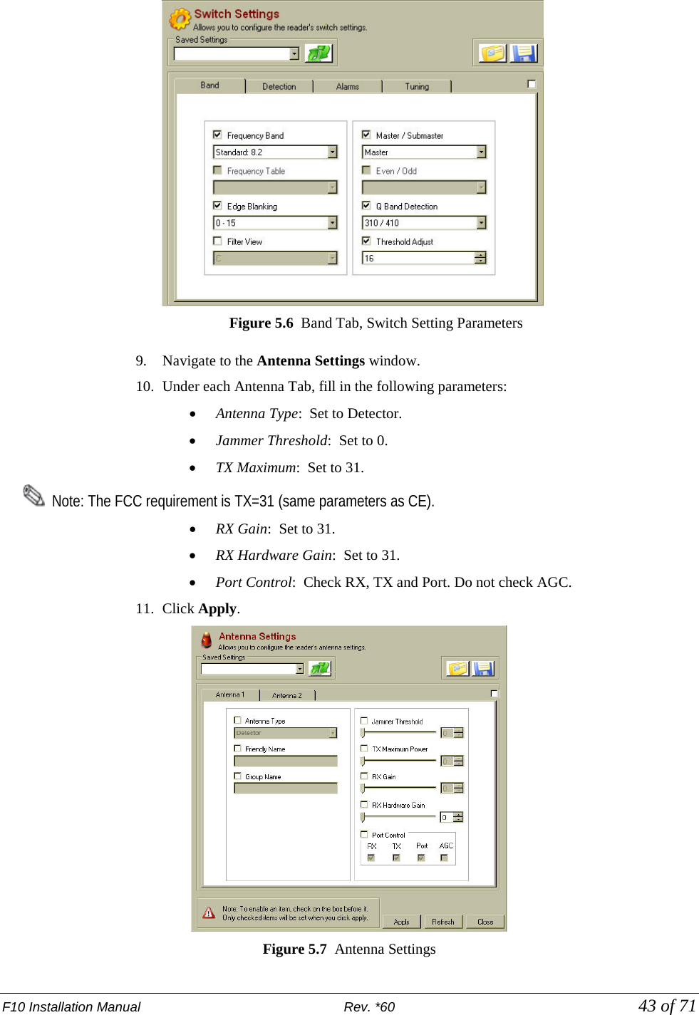
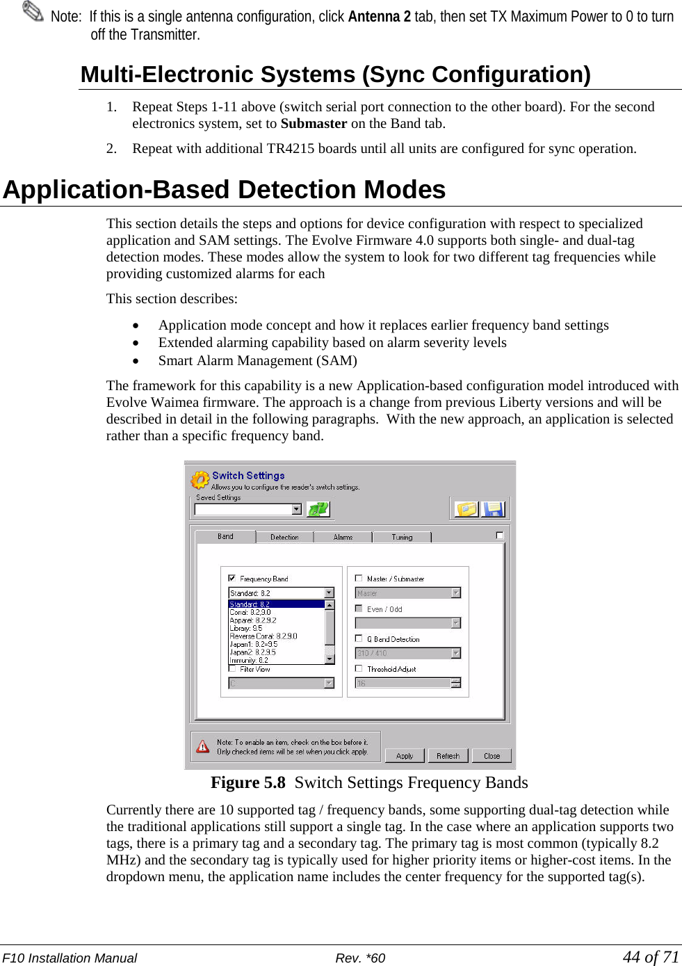
![F10 Installation Manual Rev. *60 39 of 71 CHAPTER 5 F10 SYSTEM CONFIGURATION VIA DMS Overview This chapter reviews the configuration steps for the F10 system using DMS. There are slight differences between the 1m and 2m systems. Antenna tuning is covered in Chapter 6: F10 Tuning. Please follow the tuning guide to optimize system performance after configuring the F10 system. Note: Please use DMS version 1.8.31 or later. TR4215 firmware version must be 4.00 or later. System Setup Using DMS The DMS setup procedure varies between the two overall system configurations: • Single-Electronics System (i.e. only one or two antenna assemblies) and • Multi-Electronics System (more than two antennas must be synced when less than 12m [40ft] apart). Note: 12m [40ft] is the minimum distance where a sync cable is not required between two (2) separate single-electronics systems, but this should be taken on a case by case basis. See Appendix C for minimum distances to avoid interactions. The instructions below emphasize which parameters should be setup for the TR4215 board. In either case, setup is similar but an extra step is needed for Multi-Antenna configuration. A basic knowledge of the DMS tool is assumed. Note: Refer to the Field Service Diagnostic Management User’s Guide for general help using the DMS tool. Single-Electronic System Setup The basic setup process consists of following steps: 1. Make a new DMS connection. 2. Configure the electronic(s) for Detector mode. 3. Set up alarm responses based on customer needs.](https://usermanual.wiki/Checkpoint-Systems/EVOLVEF10/User-Guide-1891276-Page-39.png)


![F10 Installation Manual Rev. *60 64 of 71 Dimensions Width: 10.50cm [4.13in] Length: 15.24cm [6.00in] Height: 8.64cm [3.40in] Power Supply Used in Australia Model: The power supply used in Australia is the ETE 2.5A model, shown below. Specifications: This unit operates at 240V 50Hz .38A; the output voltage remains 24VDC. Dimensions: Width:10.5cm Length 15.7cm Height: 7.0cm](https://usermanual.wiki/Checkpoint-Systems/EVOLVEF10/User-Guide-1891276-Page-64.png)
![F10 Installation Manual Rev. *60 65 of 71 APPENDIX B PARTS LISTS F10 Parts List CKP Part # OEM Part # Description 7939172 n/a .38cm x 1.3cm (#7 x ½”) hex head screw 7308823 2348 Power Fastener Zip-it with .42cm x 2.5cm (#8 x 1”) panhead screw 7366291 9439 Power Fastener .79cm (5/16”) lead anchor 7917157 n/a 5.484 mm x 38.1 mm (#12 x 1 ½”) panhead screw 7257241 Belden 8723 Consolidated 5594 Approved Sync Cable (only used if syncing multiple electronics enclosures) Contractor Supplied VC9984 PVC cement for bonding fittings Contractor Supplied TRM, 1101, 1004 Ardex TRM – Transportation Repair Mortar, QUIKRETE® Concrete Mix (No. 1101), QUIKRETE® Fast-Setting Concrete Mix (No. 1004) Contractor Supplied n/a Sand used to level bottom of trough under antenna assembly Contractor Supplied n/a 1.25cm [1/2”] ENT Tubing (conduit), contractor supplied. Used to house 15.1m [50ft] coax cable in new installations before slab is poured.](https://usermanual.wiki/Checkpoint-Systems/EVOLVEF10/User-Guide-1891276-Page-65.png)
![F10 Installation Manual Rev. *60 66 of 71 APPENDIX C INTERACTIONS F10 System – Proximity to Deactivation Units The table below lists minimum distances where Counterpoint IX or D11 Deactivators can be located away from a F10 system antenna. Deactivators do not affect the F10 system performance. However, in 4 and 6 Mode, if any F10 system is located inside a 1.8m [6ft] radius from the deactivator, false alarms may occur because the deactivator “sees” the system. It is not possible to slave a deactivator to a system with Strata-based electronics. Note: The deactivator will intermittently alarm as it sees the F10 pulsing, these alarms will occur on average every 30 seconds. Distance to F10 System MODELS (all with pad) Up to 1.8m (6.0') > 1.8m (6.0') CP IX/D11 4 Mode Deactivator Phantoms (see note) No Interactions CP IX/D11 5 Mode No Interactions No Interactions](https://usermanual.wiki/Checkpoint-Systems/EVOLVEF10/User-Guide-1891276-Page-66.png)
![F10 Installation Manual Rev. *60 67 of 71 F10 System – Proximity to Other Systems Please refer to the table below for details on how close systems can be to one another. EVOLVE F10 Minimum Separation w/o Slaving Slave Options Any pedestal or floor system 12m [40 feet] Slave Pillar / Frame 4.6m [15 feet] None QS4000XT 4.6m [15 feet] None QS2000 4.6m [15 feet] None Signature 4.6m [15 feet] None Quicksilver 4.6m [15 feet] None QS6500 7.6m [25 feet] None QS45/55 7.6m [25 feet] None](https://usermanual.wiki/Checkpoint-Systems/EVOLVEF10/User-Guide-1891276-Page-67.png)